Page 38 of 788

ON-VEHICLE SERVICE
ENGINE COOLING14-24
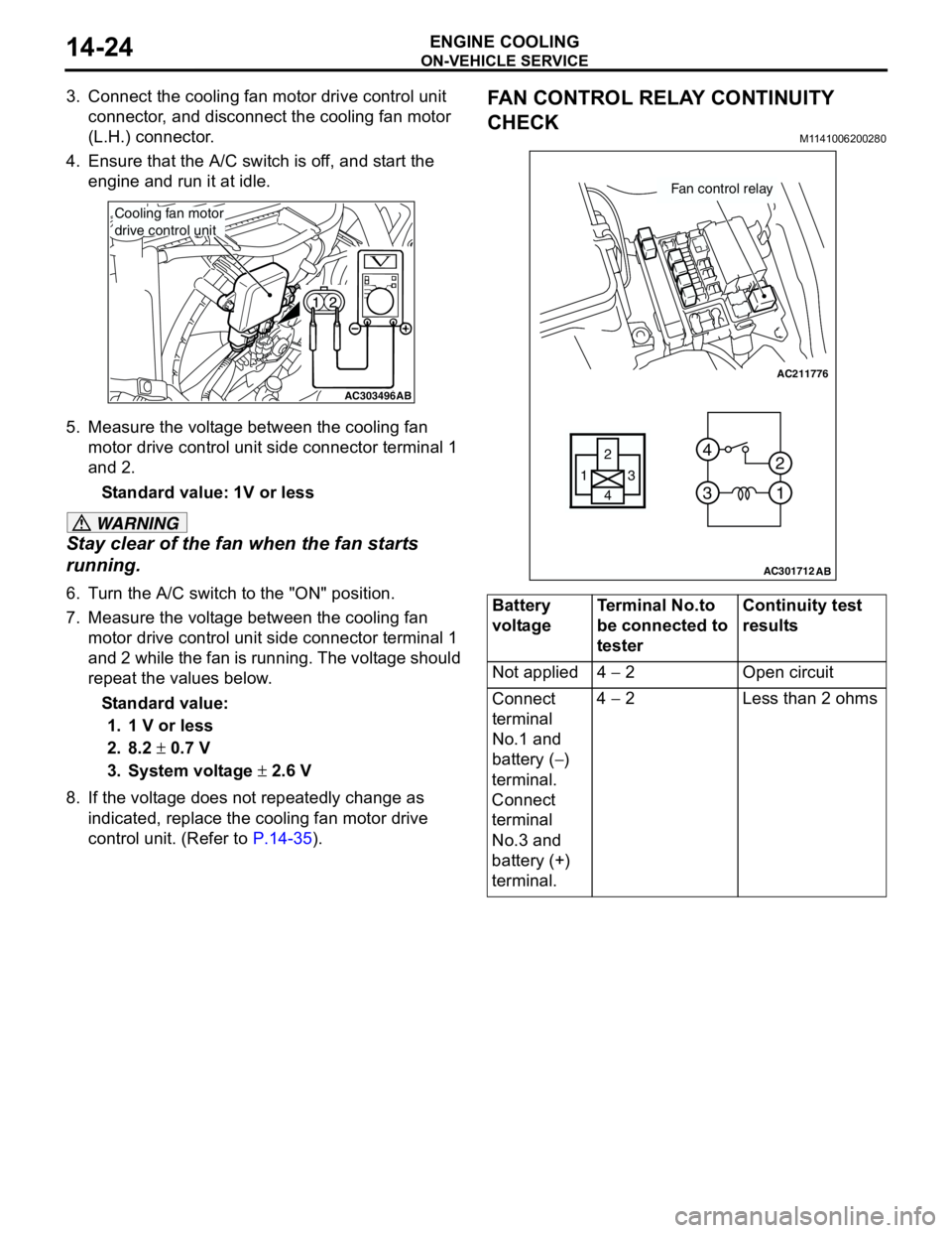
3. Connect the cooling fan motor drive control unit
connector, and disconnect the cooling fan motor
(L.H.) connector.
4. Ensure that the A/C switch is off, and start the
engine and run it at idle.
5. Measure the voltage between the cooling fan
motor drive control unit side connector terminal 1
and 2.
Standard value: 1V or less
WARNING
Stay clear of the fan when the fan starts
running.
6. Turn the A/C switch to the "ON" position.
7. Measure the voltage between the cooling fan
motor drive control unit side connector terminal 1
and 2 while the fan is running. The voltage should
repeat the values below.
Standard value:
1. 1 V or less
2. 8.2 ± 0.7 V
3. System voltage ± 2.6 V
8. If the voltage does not repeatedly change as
indicated, replace the cooling fan motor drive
control unit. (Refer to P.14-35).
FAN CONTROL RELAY CONTINUITY
CHECK
M1141006200280
AC303496AB
Cooling fan motor
drive control unit
Battery
voltageTerminal No.to
be connected to
testerContinuity test
results
Not applied 4 − 2 Open circuit
Connect
terminal
No.1 and
battery (−)
terminal.
Connect
terminal
No.3 and
battery (+)
terminal.4 − 2 Less than 2 ohms
AC211776
13
4 2
3 4
1 2
AC301712
Fan control relay
AB
Page 39 of 788
ON-VEHICLE SERVICE
ENGINE COOLING14-25
COOLING FAN MOTOR CHECKM11410071000601. Remove the cooling fan motor connector.
2. Check to see that the cooling fan motor of the
radiator turns when applying battery power
between the connector terminal 1 and 2 of the
cooling fan motor. Also check to see that there is
no abnormal sound coming from the cooling fan
motor at this time.
3. If the cooling fan motor is defective, replace it.
(Refer to P.14-35).
1 2
AC303501AB
Cooling fan motor drive control unit
Cooling fan motor
(L.H.) connector
1 2
AC303502AB
Cooling fan motor
drive control unit
Cooling fan motor
(R.H.) connector
<4G1 with A/C>
Page 40 of 788
THERMOSTAT
ENGINE COOLING14-26
THERMOSTAT
REMOVAL AND INSTALLATIONM1141002400442
Pre-removal and Post-installation Operation
•Engine Coolant Draining and Refilling (Refer to P.14-22).
•Air Cleaner Assembly Removal and Installation (Refer to
GROUP 15 P.15-3).
•Battery Removal and Installation
AC203409AC
4
3 6 7
22 ± 4 N·m
<4G1>
AC301429
1
2
36 7
13 ± 2 N·m
AD
5
<4G6>
Page 57 of 788

INLET MANIFOLD
INTAKE AND EXHAUST15-5
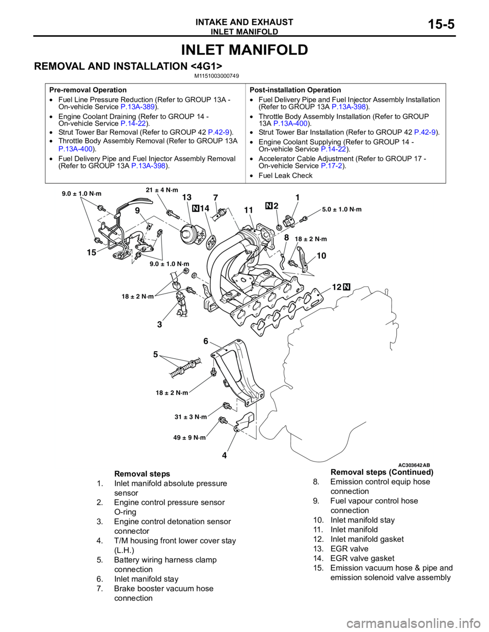
INLET MANIFOLD
REMOVAL AND INSTALLATION <4G1>M1151003000749
Pre-removal Operation
•Fuel Line Pressure Reduction (Refer to GROUP 13A -
On-vehicle Service P.13A-389).
•Engine Coolant Draining (Refer to GROUP 14 -
On-vehicle Service P.14-22).
•Strut Tower Bar Removal (Refer to GROUP 42 P.42-9).
•Throttle Body Assembly Removal (Refer to GROUP 13A
P.13A-400).
•Fuel Delivery Pipe and Fuel Injector Assembly Removal
(Refer to GROUP 13A P.13A-398).Post-installation Operation
•Fuel Delivery Pipe and Fuel Injector Assembly Installation
(Refer to GROUP 13A P.13A-398).
•Throttle Body Assembly Installation (Refer to GROUP
13A P.13A-400).
•Strut Tower Bar Installation (Refer to GROUP 42 P.42-9).
•Engine Coolant Supplying (Refer to GROUP 14 -
On-vehicle Service P.14-22).
•Accelerator Cable Adjustment (Refer to GROUP 17 -
On-vehicle Service P.17-2).
•Fuel Leak Check
AC303642AB
15
3
6
5
412 10 71
2
11
913
14
21 ± 4 N·m
9.0 ± 1.0 N·m
9.0 ± 1.0 N·m
18 ± 2 N·m
18 ± 2 N·m18 ± 2 N·m5.0 ± 1.0 N·m
31 ± 3 N·m
49 ± 9 N·m
N
N
N
8
Removal steps
1. Inlet manifold absolute pressure
sensor
2. Engine control pressure sensor
O-ring
3. Engine control detonation sensor
connector
4. T/M housing front lower cover stay
(L.H.)
5. Battery wiring harness clamp
connection
6. Inlet manifold stay
7. Brake booster vacuum hose
connection8. Emission control equip hose
connection
9. Fuel vapour control hose
connection
10. Inlet manifold stay
11. Inlet manifold
12. Inlet manifold gasket
13. EGR valve
14. EGR valve gasket
15. Emission vacuum hose & pipe and
emission solenoid valve assembly Removal steps (Continued)
Page 59 of 788
EXHAUST MANIFOLD
INTAKE AND EXHAUST15-7
INSPECTIONM1151003100616
Check the following points; replace the part if a
problem is found.
Inlet Manifold Check
1. Check for damage or cracking of any part.2. Clogging of the negative pressure (vacuum) outlet
port, or clogging of the exhaust gas recirculation
passages.
3. Using a straight edge and feeler gauge, check for
distortion of the cylinder head installation surface.
Standard value: 0.15 mm or less
Limit: 0.20 mm
EXHAUST MANIFOLD
REMOVAL AND INSTALLATION <4G1>M1151003300568
8. Battery wiring harness clamp
9. Inlet manifold stay
10. Inlet manifold
11. Inlet manifold gasket
12. Emission vacuum hose & pipe and
emission solenoid valve assembly
13. EGR valve
14. EGR valve gasketRemoval steps (Continued)
AC30366250 ± 10 N·m 24 ± 4 N·m
35 ± 6 N·m17 ± 2 N·m 29 ± 3 N·m
N
3
7
12 4
N
6
8
44 ± 5 N·m
AB
9
5N
29 ± 3 N·m
29 ± 3 N·m
29 ± 3 N·m
(Engine oil)
Page 66 of 788

CHARGING SYSTEM
ENGINE ELECTRICAL16-2
CHARGING SYSTEM
GENERAL INFORMATIONM1161000100522
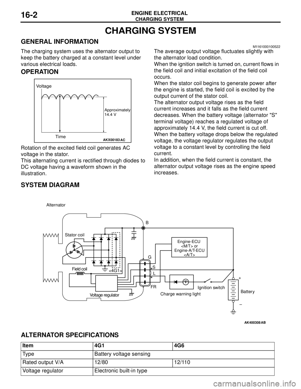
The charging system uses the alternator output to
keep the battery charged at a constant level under
various electrical loads.
OPERATION
Rotation of the excited field coil generates AC
voltage in the stator.
This alternating current is rectified through diodes to
DC voltage having a waveform shown in the
illustration.The average output voltage fluctuates slightly with
the alternator load condition.
When the ignition switch is turned on, current flows in
the field coil and initial excitation of the field coil
occurs.
When the stator coil begins to generate power after
the engine is started, the field coil is excited by the
output current of the stator coil.
The alternator output voltage rises as the field
current increases and it falls as the field current
decreases. When the battery voltage (alternator "S"
terminal voltage) reaches a regulated voltage of
approximately 14.4 V, the field current is cut off.
When the battery voltage drops below the regulated
voltage, the voltage regulator regulates the output
voltage to a constant level by controlling the field
current.
In addition, when the field current is constant, the
alternator output voltage rises as the engine speed
increases.
SYSTEM DIAGRAM
ALTERNATOR SPECIFICATIONS
AKX00183
Voltage
Time
Approximately
14.4 V
AC
AK400308
Alternator
B
Stator coil
Engine-ECU
or
Engine-A/T-ECU
G
S
L
FR <4G1>
Voltage regulatorCharge warning lightIgnition switch
Battery Field coil
+
–
AB
Item 4G1 4G6
Type Battery voltage sensing
Rated output V/A 12/80 12/110
Voltage regulator Electronic built-in type
Page 67 of 788

CHARGING SYSTEM
ENGINE ELECTRICAL16-3
SERVICE SPECIFICATIONSM1161000300258
SPECIAL TOOLM1161000600163
ON-VEHICLE SERVICE
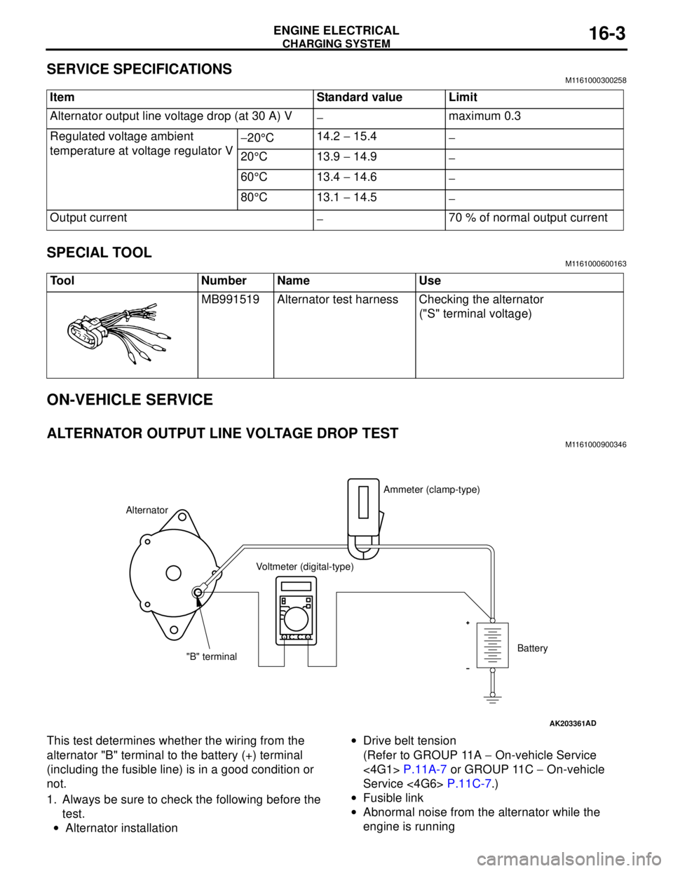
ALTERNATOR OUTPUT LINE VOLTAGE DROP TESTM1161000900346
This test determines whether the wiring from the
alternator "B" terminal to the battery (+) terminal
(including the fusible line) is in a good condition or
not.
1. Always be sure to check the following before the
test.
•Alternator installation•Drive belt tension
(Refer to GROUP 11A − On-vehicle Service
<4G1> P.11A-7 or GROUP 11C − On-vehicle
Service <4G6> P.11C-7.)
•Fusible link
•Abnormal noise from the alternator while the
engine is running Item Standard value Limit
Alternator output line voltage drop (at 30 A) V
−maximum 0.3
Regulated voltage ambient
temperature at voltage regulator V−20°C14.2 − 15.4
−
20°C 13.9 − 14.9
−
60°C 13.4 − 14.6
−
80°C 13.1 − 14.5
−
Output current
−70 % of normal output current
Tool Number Name Use
MB991519 Alternator test harness Checking the alternator
("S" terminal voltage)
AK203361AD
AlternatorAmmeter (clamp-type)
Voltmeter (digital-type)
"B" terminalBattery
Page 68 of 788

CHARGING SYSTEM
ENGINE ELECTRICAL16-4
2. Turn the ignition switch to the "LOCK" (OFF)
position.
3. Disconnect the negative battery cable.
4. Connect a clamp-type DC test ammeter with a
range of 0 − 120 A to the alternator "B" terminal
output wire.
NOTE: The way of disconnecting the alternator
output wire and of connecting the ammeter is
possibly not found the problem that the output
current is dropping due to the insufficient
connection between terminal "B" and the output
wire.
5. Connect a digital-type voltmeter between the
alternator "B" terminal and the battery (+)
terminal. [Connect the (+) lead of the voltmeter to
the "B" terminal and the connect the (-) lead of the
voltmeter to the battery (+) cable].
6. Reconnect the negative battery cable.
7. Connect a tachometer or the MUT-II/III (Refer to
GROUP 11A − On-vehicle Service − Idle speed
check <4G1> P.11A-11 or GROUP 11C −
On-vehicle Service − Idle speed check <4G6>
P.11C-11).
8. Leave the hood open.
9. Start the engine.
10.With the engine running at 2,500 r/min, turn the
headlamps and other lamps on and off to adjust
the alternator load so that the value displayed on
the ammeter is slightly above 30 A.Adjust the engine speed by gradually decreasing
it until the value displayed on the ammeter is 30
A. Take a reading of the value displayed on the
voltmeter at this time.
Limit: maximum 0.3 V
NOTE: When the alternator output is high and the
value displayed on the ammeter does not
decrease until 30 A, set the value to 40 A. Read
the value displayed on the voltmeter at this time.
When the value range is 40 A, the limit is
maximum 0.4 V.
11.If the value displayed on the voltmeter is above
the limit value, there is probably a malfunction in
the alternator output wire, so check the wiring
between the alternator "B" terminal and the
battery (+) terminal (including fusible link).
If a terminal is not sufficiently tight or if the
harness has become discolored due to
overheating, repair and then test again.
12.After the test, run the engine at idle.
13.Turn off all lamps and the ignition switch.
14.Remove the tachometer or the MUT-II/III.
15.Disconnect the negative battery cable.
16.Disconnect the ammeter and voltmeter.
17.Connect the negative battery cable.