2005 MITSUBISHI LANCER warning
[x] Cancel search: warningPage 2 of 788

WARNINGS REGARDING SERVICING OF SUPPLEMENTAL
RESTRAINT SYSTEM (SRS) EQUIPPED VEHICLES
(1) Improper service or maintenance of any component of the SRS or any SRS-related component,
can lead to personal injury or death to service personnel (from inadvertent firing of the air bag)
or to the driver and passenger (from rendering the SRS inoperative).
(2) The SRS components and seat belt with pretensioner should not be subjected to heat, so
remove the SRS-ECU, driver’s and front passenger’s air bag modules, clock spring, side air bag
modules, and seat belt -pre-tensioner before drying or baking the vehicle after painting.
• SRS-ECU, air bag module and clock spring 93°C or more
• Seat belt with pre-tensioner: 90°C or more
(3) Service or maintenance of any SRS component or SRS-related component must be performed
only at an authorized MITSUBISHI dealer.
(4) MITSUBISHI dealer personnel must thoroughly review this Manual, and especially its GROUP
52B - Supplemental Restraint System (SRS), before beginning any service or maintenance of
any component of the SRS or any SRS-related component.
NOTE
Section titles with asterisks (*) in the table of contents in each group indicate operations requiring warnings.
Page 8 of 788

GENERAL INFORMATION
ENGINE LUBRICATION12-2
GENERAL INFORMATION
M1121000100357
The lubrication method is a fully force-fed, full-flow
filtration type. The engine oil pump is a trochoid type
which is driven by the crankshaft <4G1>.The engine
oil pump is a gear type which is driven by the
crankshaft via the balancer timing belt <4G6>.
ENGINE OILS
Health Warning
Prolonged and repeated contact with mineral oil will
result in the removal of natural fats from the skin,
leading to dryness, irritation and dermatitis. In
addition, used engine oil contains potentially harmful
contaminants which may cause skin cancer.
Adequate means of skin protection and washing
facilities must be provided.
Recommended Precautions
The most effective precaution is to adapt working
practices which prevent, as far as practicable, the
risk of skin contact with mineral oils, for example by
using enclosed systems for handling used engine oil
and by degreasing components, where practicable,
before handling them. Other precautions:
•Avoid prolonged and repeated contact with oils,
particularly used engine oils.
•Wear protective clothing, including impervious
gloves where practicable.•Avoid contaminating clothes, particularly
underpants, with oil.
•Do not put oily rags in pockets, the use of overalls
without pockets will avoid this.
•Do not wear heavily soiled clothing and
oil-impregnated foot-wear. Overalls must be
cleaned regularly and kept separate from
personal clothing.
•Where there is a risk of eye contact, eye
protection should be worn, for example, chemical
goggles or face shields; in addition an eye wash
facility should be provided.
•Obtain first aid treatment immediately for open
cuts and wounds.
•Wash regularly with soap and water to ensure all
oil is removed, especially before meals (skin
cleansers and nail brushes will help). After
cleaning, the application of preparations
containing lanolin to replace the natural skin oils
is advised.
•Do not use petrol, kerosine, diesel fuel, gas oil,
thinners or solvents for cleaning skin.
•Use barrier creams, applying them before each
work period, to help the removal of oil from the
skin after work.
•If skin disorders develop, obtain medical advice
without delay.
SERVICE SPECIFICATION
M1121000300232
LUBRICANT
M1121000400433
Item Standard value
Oil pressure kPa at idle 29 or more
at 3,500 r/min 294 − 686
Item Specification
Engine oil ACEA classification A1, A2 or A3
Engine oil API classification SG or higher
Engine oil quantity L 4G1 Oil filter 0.3
To t a l 3 . 3
4G6 Oil filter 0.3
To t a l 4 . 3
Page 36 of 788

ON-VEHICLE SERVICE
ENGINE COOLING14-22
ON-VEHICLE SERVICE
ENGINE COOLANT LEAK CHECKM1141001000300
WARNING
When pressure testing the cooling system,
slowly release cooling system pressure to
avoid getting burned by hot coolant.
CAUTION
•Be sure to completely clean away any
moisture from the places checked.
•When the tester is taken out, be careful not to
spill any coolant.
•Be careful when installing and removing the
tester and when testing not to deform the
filler neck of the radiator.
1. Check that the coolant level is up to the filler neck.
Install a radiator tester and apply 160 kPa
pressure, and then check for leakage from the
radiator hose or connections.
2. If there is leakage, repair or replace the
appropriate part.
RADIATOR CAP VALVE OPENING
PRESSURE CHECK
M1141001300389
NOTE: Be sure that the cap is clean before
testing. Rust or other foreign material on the cap
seal will cause an improper reading.
1. Use a cap adapter to attach the cap to the tester.2. Increase the pressure until the indicator of the
gauge stops moving.
Minimum limit: 83 kPa
Standard value: 93 − 123 kPa
3. Replace the radiator cap if the reading does not
remain at or above the limit.
ENGINE COOLANT REPLACEMENTM1141001200434
WARNING
When removing the radiator cap, use care to
avoid contact with hot coolant or steam.
Place a shop towel over the cap and turn the
cap counterclockwise a little to let the
pressure escape through the vinyl tube.
After relieving the steam pressure, remove
the cap by slowly turning it
counterclockwise.
1. Drain the water from the radiator, heater core and
engine after unplugging the radiator drain plug
and removing the radiator cap.
2. Drain the water in the water jacket by unplugging
the drain plug of the cylinder block.
3. Remove the radiator condenser tank and drain
the coolant.
4. Drain the coolant then clean the path of the
coolant by injecting water into the radiator from
the radiator cap area.
ACX01844
Cap adapter
Adapter
AC
AC211643AB
Cap adapter
AC208283AC
Cylinder block
drain plug
<4G1>
Inlet side
AC303355
<4G6>
Inlet side
Cylinder block
drain plug
AB
Page 38 of 788

ON-VEHICLE SERVICE
ENGINE COOLING14-24
3. Connect the cooling fan motor drive control unit
connector, and disconnect the cooling fan motor
(L.H.) connector.
4. Ensure that the A/C switch is off, and start the
engine and run it at idle.
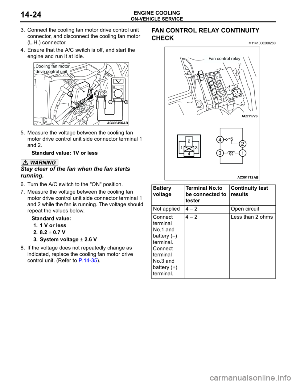
5. Measure the voltage between the cooling fan
motor drive control unit side connector terminal 1
and 2.
Standard value: 1V or less
WARNING
Stay clear of the fan when the fan starts
running.
6. Turn the A/C switch to the "ON" position.
7. Measure the voltage between the cooling fan
motor drive control unit side connector terminal 1
and 2 while the fan is running. The voltage should
repeat the values below.
Standard value:
1. 1 V or less
2. 8.2 ± 0.7 V
3. System voltage ± 2.6 V
8. If the voltage does not repeatedly change as
indicated, replace the cooling fan motor drive
control unit. (Refer to P.14-35).
FAN CONTROL RELAY CONTINUITY
CHECK
M1141006200280
AC303496AB
Cooling fan motor
drive control unit
Battery
voltageTerminal No.to
be connected to
testerContinuity test
results
Not applied 4 − 2 Open circuit
Connect
terminal
No.1 and
battery (−)
terminal.
Connect
terminal
No.3 and
battery (+)
terminal.4 − 2 Less than 2 ohms
AC211776
13
4 2
3 4
1 2
AC301712
Fan control relay
AB
Page 66 of 788

CHARGING SYSTEM
ENGINE ELECTRICAL16-2
CHARGING SYSTEM
GENERAL INFORMATIONM1161000100522
The charging system uses the alternator output to
keep the battery charged at a constant level under
various electrical loads.
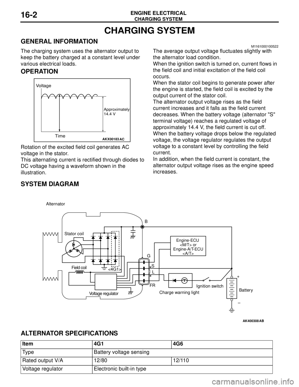
OPERATION
Rotation of the excited field coil generates AC
voltage in the stator.
This alternating current is rectified through diodes to
DC voltage having a waveform shown in the
illustration.The average output voltage fluctuates slightly with
the alternator load condition.
When the ignition switch is turned on, current flows in
the field coil and initial excitation of the field coil
occurs.
When the stator coil begins to generate power after
the engine is started, the field coil is excited by the
output current of the stator coil.
The alternator output voltage rises as the field
current increases and it falls as the field current
decreases. When the battery voltage (alternator "S"
terminal voltage) reaches a regulated voltage of
approximately 14.4 V, the field current is cut off.
When the battery voltage drops below the regulated
voltage, the voltage regulator regulates the output
voltage to a constant level by controlling the field
current.
In addition, when the field current is constant, the
alternator output voltage rises as the engine speed
increases.
SYSTEM DIAGRAM
ALTERNATOR SPECIFICATIONS
AKX00183
Voltage
Time
Approximately
14.4 V
AC
AK400308
Alternator
B
Stator coil
Engine-ECU
Engine-A/T-ECU
G
S
L
FR <4G1>
Voltage regulatorCharge warning lightIgnition switch
Battery Field coil
+
–
AB
Item 4G1 4G6
Type Battery voltage sensing
Rated output V/A 12/80 12/110
Voltage regulator Electronic built-in type
Page 69 of 788

CHARGING SYSTEM
ENGINE ELECTRICAL16-5
OUTPUT CURRENT TESTM1161001000368
This test determines whether the alternator output
current is normal.
1. Before the test, always be sure to check the
following.
•Alternator installation
•Battery (Refer to GROUP 54A − Battery −
On-vehicle Service P.54A-5).
NOTE: The battery should be slightly discharged.
The load needed by a fully-charged battery is
insufficient for an accurate test.
•Drive belt tension
(Refer to GROUP 11A − On-vehicle Service <4G1>
P.11A-7 or GROUP 11C − On-vehicle Service
<4G6> P.11C-7.)
•Fusible link
•Abnormal noise from the alternator while the
engine is running.
2. Turn the ignition switch to the "LOCK" (OFF)
position.
3. Disconnect the negative battery cable.CAUTION
Never use clips but tighten bolts and nuts to
connect the line. Otherwise loose connections
(e.g. using clips) will lead to a serious accident
because of high current.
4. Connect a clamp-type DC test ammeter with a
range of 0 − 120 A to the alternator "B" terminal
output wire.
NOTE: The way of disconnecting the alternator
output wire and of connecting the ammeter is
possibly not found the problem that the output
current is dropping due to the insufficient
connection between terminal "B" and the output
wire.
5. Connect a voltmeter with a range of 0 − 20 V
between the alternator "B" terminal and the earth
[Connect the (+) lead of the voltmeter to the "B"
terminal, and then connect the (-) lead of the
voltmeter to the earth].
6. Connect the negative battery cable.
AK203362
Alternator Ammeter
(clamp-type)
Voltmeter
Battery Inition switch
Engine-ECU
Engine-A/T-ECU
Load
B
FR
L
S
G +
AH
–
Charging indicator
Brake warning light
Page 74 of 788

CHARGING SYSTEM
ENGINE ELECTRICAL16-10
EXAMPLE OF ABNORMAL WAVEFORMS
NOTE: .
1. The size of the waveform patterns differs largely, depending on the adjustment of the variable knob on the
oscilloscope.
2. Identification of abnormal waveforms is easier when there is a large output current (regulator is not
operating). (Waveforms can be observed when the headlamps are illuminated.)
3. Check the conditions of the charging warning lamp (illuminated/not illuminated). Also, check the charging
system totally.
Abnormal waveform Problem cause
Example 1 Open diode
Example 2 Short in diode
AKX00191
AKX00192
Page 75 of 788

CHARGING SYSTEM
ENGINE ELECTRICAL16-11
Example 3 Broken wire in
stator coil
Example 4 Short in stator
coil
Example 5
At this time, the charging warning lamp is illuminated.Open
supplementary
diode Abnormal waveform Problem cause
AKX00193
AKX00194
AKX00195