Page 167 of 788

TROUBLESHOOTING
WHEEL AND TYRE31-5
1. After balancing the wheel, loosen the wing nut
and turn the wheel 180° against the balancer's
hub. Then re-tighten the wing nut and check the
balance again. Repeat wheel balance if
necessary.
2. Turn the wheel again 180° against the balancer's
hub. If the wheel becomes out-of-balance each
time it is turned against the balancer's hub, the
wheel balancer may require calibration.
1. Mount an undamaged original-equipment alloy
rim and tyre assembly (wheel) onto your
off-the-car wheel balancer. Balance the wheel.
2. <>
Loosen the balancer wing nut, rotate the wheel a
half-turn (180°), and retighten the nut. Recheck
the balance.
•If the imbalance is 5g or less, the zero calibration
is OK. Rebalance the wheel, then go to Step 4 to
check static balance.
•If the imbalance is more than 5g, go to Step 3.
3. Loosen the balancer wing nut, rotate the wheel
1/4 turn (90°), and retighten the nut. Recheck the
wheel balance.
•If the imbalance is 5g or less, the wheel may not
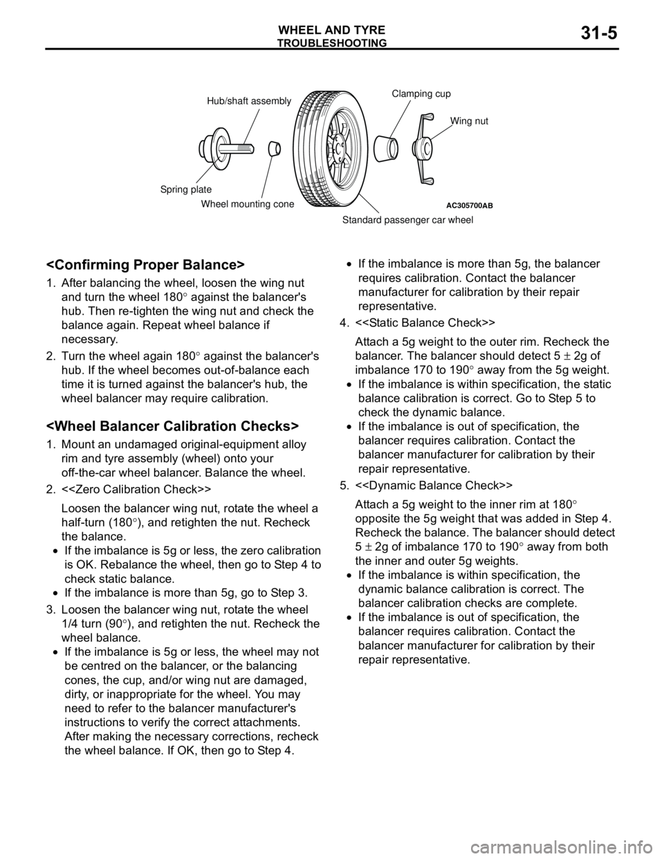
be centred on the balancer, or the balancing
cones, the cup, and/or wing nut are damaged,
dirty, or inappropriate for the wheel. You may
need to refer to the balancer manufacturer's
instructions to verify the correct attachments.
After making the necessary corrections, recheck
the wheel balance. If OK, then go to Step 4.•If the imbalance is more than 5g, the balancer
requires calibration. Contact the balancer
manufacturer for calibration by their repair
representative.
4. <>
Attach a 5g weight to the outer rim. Recheck the
balancer. The balancer should detect 5 ± 2g of
imbalance 170 to 190° away from the 5g weight.
•If the imbalance is within specification, the static
balance calibration is correct. Go to Step 5 to
check the dynamic balance.
•If the imbalance is out of specification, the
balancer requires calibration. Contact the
balancer manufacturer for calibration by their
repair representative.
5. <>
Attach a 5g weight to the inner rim at 180°
opposite the 5g weight that was added in Step 4.
Recheck the balance. The balancer should detect
5 ± 2g of imbalance 170 to 190° away from both
the inner and outer 5g weights.
•If the imbalance is within specification, the
dynamic balance calibration is correct. The
balancer calibration checks are complete.
•If the imbalance is out of specification, the
balancer requires calibration. Contact the
balancer manufacturer for calibration by their
repair representative.
AC305700AB
Hub/shaft assemblyClamping cup
Wing nut
Standard passenger car wheel Wheel mounting cone Spring plate
Page 168 of 788

TROUBLESHOOTING
WHEEL AND TYRE31-6
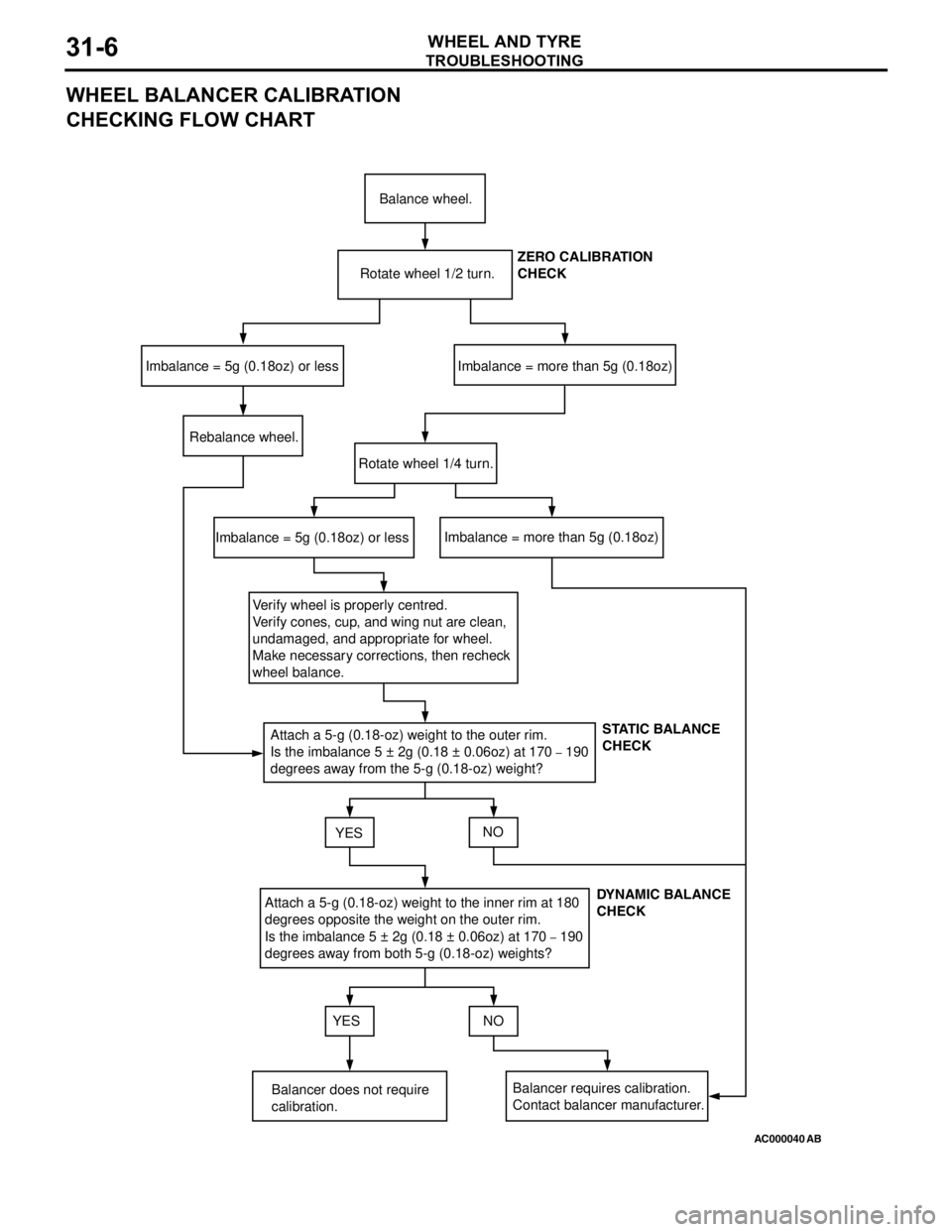
WHEEL BALANCER CALIBRATION
CHECKING FLOW CHART
AC000040
Balance wheel.
Rotate wheel 1/2 turn.
Imbalance = 5g (0.18oz) or lessImbalance = more than 5g (0.18oz)
Rebalance wheel.
Rotate wheel 1/4 turn.
Imbalance = 5g (0.18oz) or lessImbalance = more than 5g (0.18oz)
Verify wheel is properly centred.
Verify cones, cup, and wing nut are clean,
undamaged, and appropriate for wheel.
Make necessary corrections, then recheck
wheel balance.
Attach a 5-g (0.18-oz) weight to the outer rim.
Is the imbalance 5 ± 2g (0.18 ± 0.06oz) at 170
– 190
degrees away from the 5-g (0.18-oz) weight?
YESNO
Attach a 5-g (0.18-oz) weight to the inner rim at 180
degrees opposite the weight on the outer rim.
Is the imbalance 5 ± 2g (0.18 ± 0.06oz) at 170
– 190
degrees away from both 5-g (0.18-oz) weights?
YES NO
Balancer does not require
calibration.Balancer requires calibration.
Contact balancer manufacturer.ZERO CALIBRATION
CHECK
STATIC BALANCE
CHECK
DYNAMIC BALANCE
CHECK
AB
Page 173 of 788
SERVICE SPECIFICATION
POWER PLANT MOUNT32-3
SERVICE SPECIFICATION
M1321000300333
SPECIAL TOOL
M1321000600378
ItemStandard value
Protruding length of stabilizer link thread part mm 22 ± 1.5
Tool Number Name Use
MB991897 Ball joint remover Knuckle and tie rod end ball joint
disconnection
NOTE: Steering linkage puller
(MB990635 or MB991113) is also
available to disconnect knuckle and
tie rod end ball joint.
AC106827
Page 177 of 788

ENGINE ROLL STOPPER, CENTERMEMBER
POWER PLANT MOUNT32-7
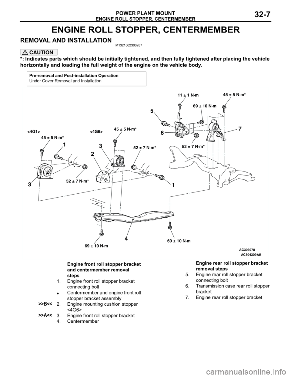
ENGINE ROLL STOPPER, CENTERMEMBER
REMOVAL AND INSTALLATIONM1321002300287
CAUTION
*: Indicates parts which should be initially tightened, and then fully tightened after placing the vehicle
horizontally and loading the full weight of the engine on the vehicle body.
Pre-removal and Post-installation Operation
Under Cover Removal and Installation
AC303978
AC304309
45 ± 5 N·m*45 ± 5 N·m*
<4G1> <4G6>
52 ± 7 N·m*52 ± 7 N·m*
45 ± 5 N·m*
52 ± 7 N·m*
11 ± 1 N·m
69 ± 10 N·m
69 ± 10 N·m69 ± 10 N·m
1
32
1 3
4
5
67
AB
Engine front roll stopper bracket
and centermember removal
steps
1. Engine front roll stopper bracket
connecting bolt
•Centermember and engine front roll
stopper bracket assembly
>>B<<2. Engine mounting cushion stopper
<4G6>
>>A<<3. Engine front roll stopper bracket
4. CentermemberEngine rear roll stopper bracket
removal steps
5. Engine rear roll stopper bracket
connecting bolt
6. Transmission case rear roll stopper
bracket
7. Engine rear roll stopper bracket
Page 179 of 788
Page 180 of 788
Page 181 of 788
Page 183 of 788

33-1
GROUP 33
FRONT
SUSPENSION
CONTENTS
GENERAL INFORMATION . . . . . . . .33-2
SERVICE SPECIFICATIONS . . . . . . .33-3
LUBRICANT . . . . . . . . . . . . . . . . . . . .33-3
SPECIAL TOOLS . . . . . . . . . . . . . . . .33-4
ON-VEHICLE SERVICE . . . . . . . . . . .33-5
FRONT WHEEL ALIGNMENT CHECK
AND ADJUSTMENT . . . . . . . . . . . . . . . . . . 33-5
LOWER ARM BALL JOINT AXIAL PLAY
CHECK . . . . . . . . . . . . . . . . . . . . . . . . . . . . 33-6
LOWER ARM BALL JOINT COVER
CHECK . . . . . . . . . . . . . . . . . . . . . . . . . . . . 33-6
STRUT ASSEMBLY . . . . . . . . . . . . . .33-7
REMOVAL AND INSTALLATION . . . . . . . . 33-7
INSPECTION . . . . . . . . . . . . . . . . . . . . . . . . 33-7
DISASSEMBLY AND REASSEMBLY . . . . . 33-8
INSPECTION . . . . . . . . . . . . . . . . . . . . . . . . 33-10
LOWER ARM . . . . . . . . . . . . . . . . . . .33-11
REMOVAL AND INSTALLATION . . . . . . . . 33-11
INSPECTION . . . . . . . . . . . . . . . . . . . . . . . . 33-12
LOWER ARM BALL JOINT COVER
REPLACEMENT . . . . . . . . . . . . . . . . . . . . . 33-12
LOWER ARM BUSHING (REAR)
REPLACEMENT . . . . . . . . . . . . . . . . . . . . . 33-13
STABILIZER BAR* . . . . . . . . . . . . . . .33-14
REMOVAL AND INSTALLATION . . . . . . . . 33-14
INSPECTION . . . . . . . . . . . . . . . . . . . . . . . . 33-17
WARNINGS REGARDING SERVICING OF SUPPLEMENTAL RESTRAINT SYSTEM (SRS) EQUIPPED VEHICLES
WARNING
•Improper service or maintenance of any component of the SRS, or any SRS-related component, can lead to
personal injury or death to service personnel (from inadvertent firing of the air bag) or to the driver and
paassenger (from rendering the SRS inoperative).
•Service or maintenance of any SRS component or SRS-related component must be performed only at an
authorized MITSUBISHI dealer.
•MITSUBISHI dealer personnel must thoroughly review this manual, and especially its GROUP 52B - Supplemental
Restraint System (SRS) before beginning any service or maintenance of any component of the SRS or any
SRS-related component.
NOTE
The SRS includes the following components: SRS air bag control unit, SRS warning light, front impact sensors, air bag module,
clock spring, and interconnecting wiring. Other SRS-related components (that may have to be removed/installed in connection
with SRS service or maintenance) are indicated in the table of contents by an asterisk (*).