Page 37 of 364

ENGINE – ENGINE ASSY
11-31
Removal guidelines
� �
A� �
Removing the drive belt
The following operations are necessary because the engine uses a
serpentine drive system with auto-tensioner.
1. Insert a 12.7sq spinner handle into the auto-tensioner tool hole,
and turn the auto-tensioner in an anti-clockwise direction before
it reaches the stopper.
2. Align hole A and hole B, insert an L-shaped hexagonal Allen
Key, to hold the position, and remove the drive belt.
Caution
If planning to re-use the drive belt, ensure that it will be
refitted the same way round, by marking the back of the belt
with chalk arrows indicating the direction of movement.
� �
B� �
Removing the power steering oil pump and the A/C
compressor
1. Remove the power steering oil pump and the A/C compressor
from the bracket with the hoses intact.
2. Secure the removed power steering oil pump and the removed
A/C compressor with string, and put them somewhere where
they will not hinder the removal or fitting of the engine ASSY.
� �
C� �
Removing the transfer ASSY and the transmission
ASSY
1. In order to prepare the special mechanical engine hanger
(MZ203830, MZ203831 or MB991928), the radiator support
upper insulator mounting bolts should be tightened on the
chassis (2 places).
2. Remove the transfer ASSY and the transmission ASSY.
AholeB hole
L-shaped
hex-
agonal
Allen
wrench
Page 56 of 364

13A-16MPI – TROUBLESHOOTING
Check the purge control solenoid valve (Refer to Section
17: Checking the exhaust gas purification system)
MUT-II/III Service data
•No.11 O
2sensor (Ref: P13A-83)*
Refer to the diagnosis code classification table (P13A-6)MUT-II/III diagnosis code
•Is the diagnosis code displayed?
Check the timing of ignition (Ref Section 11, Engine
tuning)
Check the sound made by the injector (using a
soundscope)
Check the crank angle sensor and the fitting of the timing
belt cover
If there is abnormality in the exhaust gases and code
Nos. P0201~P0204 are recorded, check the injector
system
If abnormal sensor data is recorded, carry out inspections
for each diagnosis code in order (Ref: P13A-6)
Replace the purge control solenoid valve
Code No.P0130: O
2sensor system inspection (Ref:
P13A-16)*
Go on to next page.
MUT-II/III Service data
•No.13: Intake air temperature sensor
•No.14: TPS
•No.21: Water temperature sensor
•No.25: Atmospheric pressure sensor
•No.95: MAP sensor
(Ref: P13A-24)
Proceed to OK if all service data levels are normal.
Proceed via NG even if only one of the service data
levels is abnormal.
*: Refer to the 03-1 Service Manual for the Lancer Evolution VIII (No.1036K07)
NO
OK
OK
OK
OK
OK
YES
NG
NG
NG
NG
Inspection procedureFault to be checkedReference page
11
Engine seems hesitant
13A-16Acceleration malfunction
Engine seems to stumble
Engine has a power surge
15Mis-timed ignition13A-18
35Inter-cooler water spray circuit system13A-19
37No.2 waste gate solenoid valve system13A-21
38Air temperature sensor system13A-22
Engine seems hesitant, acceleration malfunction, engine
seems to stumble, engine has a power surgeProbable causes of the malfunction
Probable causes of the malfunction are noted in the right hand
column.•Malfunction of the air/fuel mixing control system
•Malfunction of the ignition system
•Malfunction of the fuel system
•Malfunction of the intake system
•Malfunction of the exhaust gas purification system
•Failure of compression pressure
•Malfunction of the turbocharger system
5. Inspection procedure for each type of fault
Inspection procedure 11
4. Checklist of faults
Page 58 of 364

13A-18MPI – TROUBLESHOOTING
Measure the output wave from
the crank angle sensor and the
cam position sensor (using an
oscilloscope).
•Engine: idling
•Measure the output wave at
the crank angle sensor
connector B-122
•Connect test harness
(MB998478), to the connector,
and take measurements at the
pick-up harness component
•Voltage across earth at 2
•Measure the output wave at
the exhaust cam position
sensor connector B-115
•Connect test harness
(MB991709), to the connector
and take measurements at the
pick-up harness component
•Voltage across earth at 2
OK:The output wave timing
from both sensors is as
shown on P13A-25
(Main points for
oscilloscope testing).Check that the problem has been
solvedTemporary malfunction (Ref
Section 00: Dealing with
temporary malfunctions)
Replace the engine ECU
NO
OK
NG
OK
NG
NG
NG
Repair
Miss-timed ignitionProbable causes of the malfunction
Probable causes of the malfunction are noted in the right
hand column.•Malfunction of the crank angle sensor
•Malfunction of the exhaust cam position sensor
•Malfunction of the timing belt
•Malfunction of the engine ECU
Inspection procedure 15
Refer to the diagnosis code classification table (P13A-6)MUT-II/III Diagnosis code
•Is the diagnosis code displayed?YES
Repair
Replace the crank angle sensor pane
Match up the timing marks on the timing belt
Replace the exhaust cam position sensing cylinder
Temporary malfunction (Ref Section 00: Dealing with
temporary malfunctions)
Check the exhaust cam position sensing cylinder
Check the fitting of the crank angle sensor and the
exhaust cam position sensor
Check the timing marks on the timing belt
Check the crank angle sensor pane
Replace the crank angle sensor
Check that the problem has been solved
Replace the exhaust cam position sensor
Check that the problem has been solved
Replace the engine ECU
OK
OK
OK
NG
OK
NG
NG
NG
OK
OK
Page 67 of 364

13A-27MPI – TROUBLESHOOTING
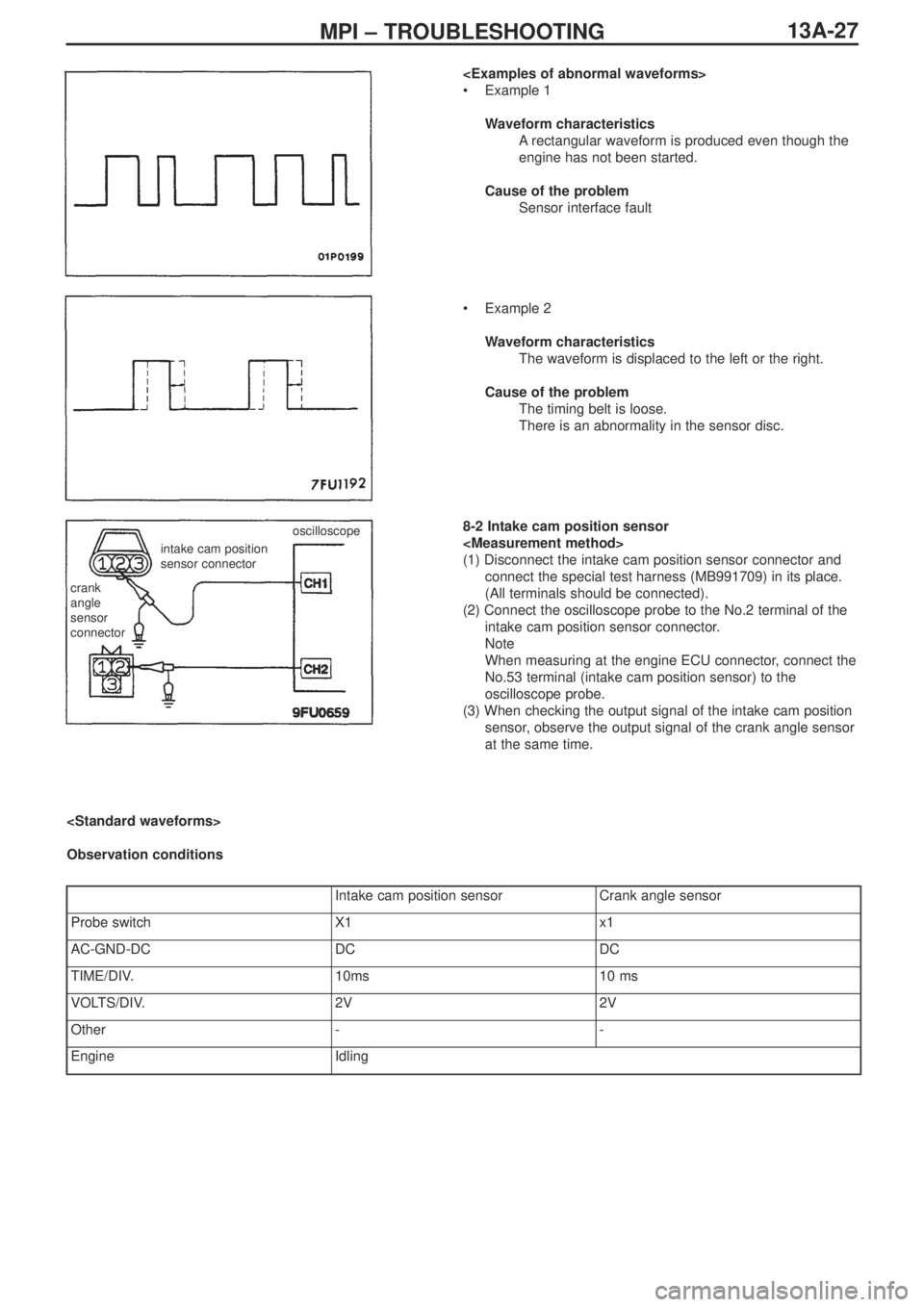
•Example 1
Waveform characteristics
Arectangular waveform is produced even though the
engine has not been started.
Cause of the problem
Sensor interface fault
•Example 2
Waveform characteristics
The waveform is displaced to the left or the right.
Cause of the problem
The timing belt is loose.
There is an abnormality in the sensor disc.
8-2 Intake cam position sensor
(1) Disconnect the intake cam position sensor connector and
connect the special test harness (MB991709) in its place.
(All terminals should be connected).
(2) Connect the oscilloscope probe to the No.2 terminal of the
intake cam position sensor connector.
Note
When measuring at the engine ECU connector, connect the
No.53 terminal (intake cam position sensor) to the
oscilloscope probe.
(3) When checking the output signal of the intake cam position
sensor, observe the output signal of the crank angle sensor
at the same time.
crank
angle
sensor
connector
intake cam position
sensor connectoroscilloscope
Observation conditions
Intake cam position sensorCrank angle sensor
Probe switchX1x1
AC-GND-DCDCDC
TIME/DIV.10ms10 ms
VOLTS/DIV.2V2V
Other--
EngineIdling
Page 69 of 364

13A-29MPI – TROUBLESHOOTING, ON-VEHICLE SERVICING
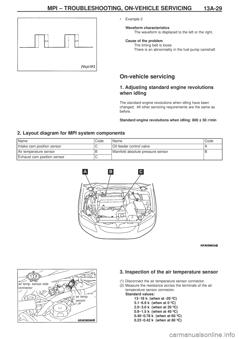
•Example 2
Waveform characteristics
The waveform is displaced to the left or the right.
Cause of the problem
The timing belt is loose
There is an abnormality in the fuel pump camshaft
On-vehicle servicing
1. Adjusting standard engine revolutions
when idling
The standard engine revolutions when idling have been
changed. All other servicing requirements are the same as
before.
Standard engine revolutions when idling: 800 ± 50 r/min
NameCodeNameCode
Intake cam position sensorCOil feeder control valveA
Air temperature sensorBManifold absolute pressure sensorB
Exhaust cam position sensorC
2. Layout diagram for MPI system components
air temp. sensor side
connector
air temp.
sensor
3. Inspection of the air temperature sensor
(1) Disconnect the air temperature sensor connector.
(2) Measure the resistance across the terminals of the air
temperature sensor connector.
Standard values:
13~18 kΩ (when at -20 ºC)
5.1~6.9 kΩ (when at 0 ºC)
2.0~3.0 kΩ (when at 20 ºC)
0.9~1.5 kΩ (when at 40 ºC)
0.40~0.78 kΩ (when at 60 ºC)
0.23~0.42 kΩ (when at 80 ºC)
Page 72 of 364
ENGINE COOLING – WATER PUMP14-2
Water pump
Removal and fitting
Jobs to be completed before removal and after fitting
•Draining and refilling of the coolant
•Removal and refitting of the timing belt (Ref Section 11)
Removal procedure
1. Alternator bracket
2. Water pump
3. Water pump gasket
4. O-ring
Fitting guidelines
� �
A� �
Fitting the O-ring
Fit the O-ring into the O-ring groove at the end of the water inlet
pipe, and insert it into the water pump after moistening with water
the places where the O-ring will make contact with the water pump.
Caution
Ensure that absolutely no engine oil, or other type of grease,
gets onto the O-ring.
Positions for fitting different sized bolts
Nominal diameter and nominal length (mm)
� �
A� �
water pump
O-ring
water inlet pipe
Page 85 of 364

ENGINE ELECTRICAL – CHARGING SYSTEM
16-1
SECTION 16
ENGINE ELECTRICAL
CONTENTS
Charging system ........................................1
General .................................................................1
Alternator...............................................................1
Ignition system...........................................4
General .................................................................4
Servicing standards...................................4
On-vehicle servicing ..................................4
Checking, cleaning and replacing spark plugs .....4
Cam position sensor .................................4
Charging system
General
The following alternator servicing guidelines have been prepared for vehicles which use the 4G63-MIVEC-T/C engine. Other
servicing guidelines remain unchanged.
Alternator
Removal and fitting
Jobs to be done before removal and after fitting
• Removal and refitting of the valence
• Checking the tension of the drive belt
• Removal and refitting of the strut tower bar
• Removal and refitting of the front exhaust pipe ASSY
• Adjustment of the accelerator cable
Page 86 of 364
ENGINE ELECTRICAL – CHARGING SYSTEM16-2
Removal procedure
1. Injector connector
2. Accelerator cable connection
3. Delivery pipe, injector, and fuel pressure
regulator ASSY
4. Insulator
5. Insulator
6. Fuel pressure solenoid valve connector
7. Fuel pressure solenoid valve ASSY
8. Knock sensor connector
9. Purge control solenoid valve connector10. Purge control solenoid valve ASSY
11.Oil level gauge and guide ASSY
12. O-ring
13. Drive belt
14. Alternator connector and terminal
• Engine mount
15. Alternator
16. Water pump pulley
17. O
2sensor connector
18. Alternator bracket
(engine oil)
� �
A� ��
�
B� �
� �
C� �