Page 12 of 364

ENGINE – CAMSHAFT, VALVE STEM SEAL11 - 6
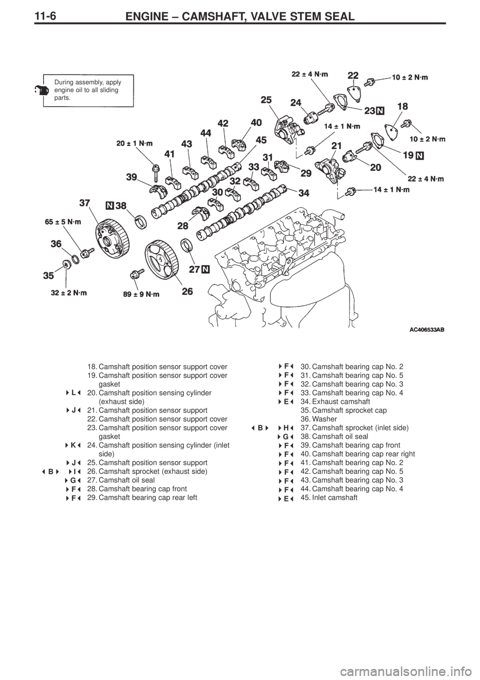
18. Camshaft position sensor support cover
19. Camshaft position sensor support cover
gasket
20. Camshaft position sensing cylinder
(exhaust side)
21. Camshaft position sensor support
22. Camshaft position sensor support cover
23. Camshaft position sensor support cover
gasket
24. Camshaft position sensing cylinder (inlet
side)
25. Camshaft position sensor support
26. Camshaft sprocket (exhaust side)
27. Camshaft oil seal
28. Camshaft bearing cap front
29. Camshaft bearing cap rear left30. Camshaft bearing cap No. 2
31. Camshaft bearing cap No. 5
32. Camshaft bearing cap No. 3
33. Camshaft bearing cap No. 4
34. Exhaust camshaft
35. Camshaft sprocket cap
36. Washer
37. Camshaft sprocket (inlet side)
38. Camshaft oil seal
39. Camshaft bearing cap front
40. Camshaft bearing cap rear right
41. Camshaft bearing cap No. 2
42. Camshaft bearing cap No. 5
43. Camshaft bearing cap No. 3
44. Camshaft bearing cap No. 4
45. Inlet camshaft
During assembly, apply
engine oil to all sliding
parts.
� �
F� �
� �
F� �
� �
F� �
� �
F� �
� �
E� �
� �
B� �
�
�
H� �
� �
G� �
� �
F� �
� �
F� �
� �
F� �
� �
F� �
� �
F� �
� �
F� �
� �
E� �
�
�
L� �
� �
J� �
� �
K� �
� �
J� �
� �
B� �
�
�
I� �
� �
G� �
� �
F� �
� �
F� �
Page 13 of 364
ENGINE – CAMSHAFT, VALVE STEM SEAL
11 - 7
46. Rocker arm
47. Rush adjuster
48. Oil delivery body
49. Spark plug
50. Valve spring retainer lock51. Valve spring retainer
52. Valve spring
53. Inlet valve stem seal
54. Exhaust valve stem seal
� �
D� �
� �
C� �
�
�
C� ��
�
B� �
� �
A� �
� �
A� �
Page 14 of 364
ENGINE – CAMSHAFT, VALVE STEM SEAL11A-8
Locations for the application of lubricant and seals
Semi-dry sealant:
Three bond 1207D
(around the lip):
Engine oil
Semi-dry sealant: Three bond 1207F
Semi-dry sealant: Three bond 1207F
Semi-dry sealant: Three bond 1207D
Page 15 of 364

ENGINE – CAMSHAFT, VALVE STEM SEAL
11 - 9
Removal guidelines
� �
A� �
Detaching the radiator upper hose
Align the indicator marks on the radiator upper hose and the hose
clamp, and then detach the radiator upper hose.
� �
B� �
Removing the camshaft sprockets
Grip the hexagonal part of the camshaft with a wrench, loosen the
mounting bolt, and remove the camshaft sprocket.
� �
C� �
Removing the valve spring retainer lock
Compress the valve spring using the special tool for compressing
valve springs (MD998772), and remove the valve spring retainer
lock.
Caution
When removing the valve spring retainer lock, each cylinder
piston should be in the top dead centre position. If pistons are
not in the top dead centre position, valves could fall into the
cylinders.
Fitting guidelines
� �
A� �
Fitting the exhaust valve stem seals and the inlet valve
stem seals
1. Inlet valve stem seals and exhaust valve stem seals can be
distinguished by checking the colour of the rubber parts.
2. Apply a small quantity of engine oil to the valve stem seals.
3. Place the valve stem component into the guides, and then insert
a new valve stem seal into the valve stem guide by using the
special tool for installing valve stem seals.
Caution
(1) Valve stem seals cannot be re-used.
(2) Please use the special tool for installing valve stem seals
(MD998737) because oil could leak if the valve stem seals
are not fitted correctly.
Indicator marks
Colour of main
body: greyColour of main
body: grey/green
Inlet sideExhaust side
Valve
Valve guide
Valve stem
seal
Page 16 of 364

ENGINE – CAMSHAFT, VALVE STEM SEAL11-10
� �
B� �
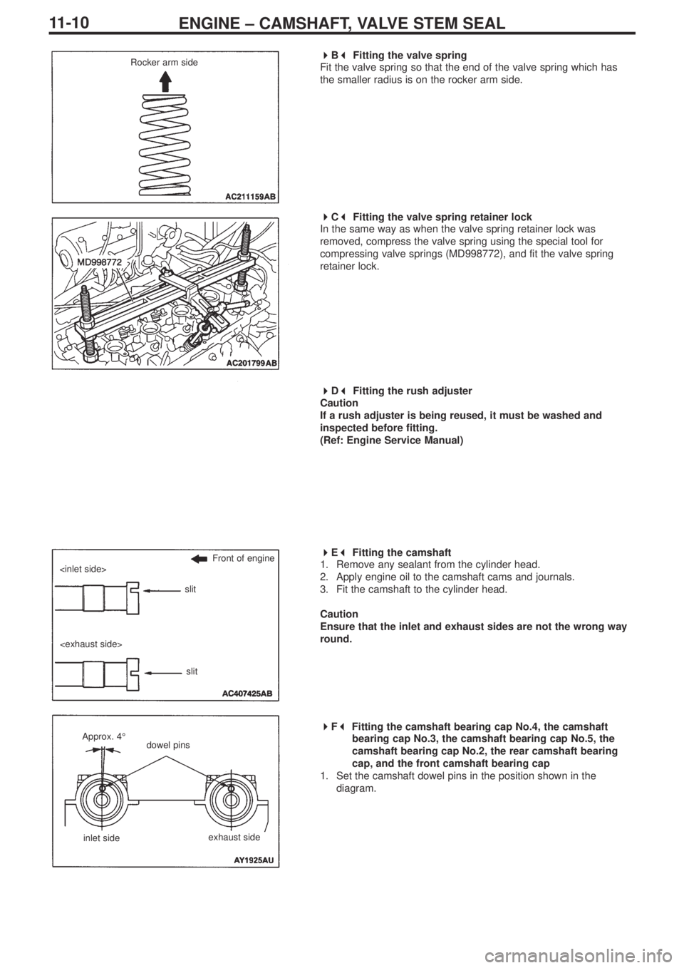
Fitting the valve spring
Fit the valve spring so that the end of the valve spring which has
the smaller radius is on the rocker arm side.
� �
C� �
Fitting the valve spring retainer lock
In the same way as when the valve spring retainer lock was
removed, compress the valve spring using the special tool for
compressing valve springs (MD998772), and fit the valve spring
retainer lock.
� �
D� �
Fitting the rush adjuster
Caution
If a rush adjuster is being reused, it must be washed and
inspected before fitting.
(Ref: Engine Service Manual)
� �
E� �
Fitting the camshaft
1. Remove any sealant from the cylinder head.
2. Apply engine oil to the camshaft cams and journals.
3. Fit the camshaft to the cylinder head.
Caution
Ensure that the inlet and exhaust sides are not the wrong way
round.
� �
F� �
Fitting the camshaft bearing cap No.4, the camshaft
bearing cap No.3, the camshaft bearing cap No.5, the
camshaft bearing cap No.2, the rear camshaft bearing
cap, and the front camshaft bearing cap
1. Set the camshaft dowel pins in the position shown in the
diagram.Rocker arm side
Front of engine
slit
slit
Approx. 4°dowel pins
inlet sideexhaust side
Page 17 of 364

ENGINE – CAMSHAFT, VALVE STEM SEAL
11 - 11
2. Because camshaft bearing caps Nos. 2~5 are the same shape,
check the identification marks on them so that the bearing cap
number and the inlet and exhaust sides are not mistaken. Then
fit them in the direction shown in the diagram.
Identification marks (stamped on the front bearing cap, and on
bearing cap Nos. 2~5).
I: inlet side
E: exhaust side
3. Apply sealant at the 8 places shown in the diagram of the top
view of the cylinder head.
Semi-dry sealant: Three bond 1207D
4. Fit the rear camshaft bearing cap in the direction indicated by
the front mark.
5. In just the same way as for bearing caps Nos. 2~5, check the
identification marks on the front camshaft bearing cap so that
the exhaust side and the inlet side are not mistaken.
6. Tighten the bearing cap mounting bolts gradually, 2~3 turns at a
time, to the specified torque.
Tightening torque: 20 ± 1 N•m
7. Check that the rocker arm has been fitted correctly.
Note
Completely wipe away any sealant that has been squeezed out.
� �
G� �
Fitting the camshaft oil seal
1. Apply engine oil around the entire circumference of the oil seal
lip.
2. Insert the oil seal using the special tool for installing the
camshaft oil seal (MD998713), as shown in the diagram.
Front of
engine
bearing cap No.
mark indicating
inlet side or
exhaust side
Front of engine
Front
of
engine
Front
of
engine
front mark
front mark
camshaft oil seal
(engine oil)
Page 18 of 364

ENGINE – CAMSHAFT, VALVE STEM SEAL11-12
� �
H� �
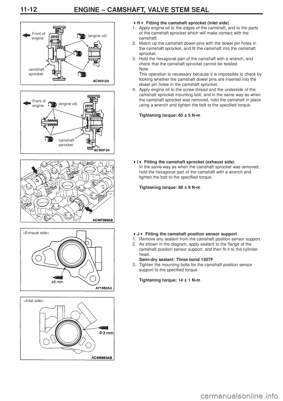
Fitting the camshaft sprocket (inlet side)
1. Apply engine oil to the edges of the camshaft, and to the parts
of the camshaft sprocket which will make contact with the
camshaft.
2. Match up the camshaft dowel pins with the dowel pin holes in
the camshaft sprocket, and fit the camshaft into the camshaft
sprocket.
3. Hold the hexagonal part of the camshaft with a wrench, and
check that the camshaft sprocket cannot be twisted.
Note
This operation is necessary because it is impossible to check by
looking whether the camshaft dowel pins are inserted into the
dowel pin holes in the camshaft sprocket.
4. Apply engine oil to the screw thread and the underside of the
camshaft sprocket mounting bolt, and in the same way as when
the camshaft sprocket was removed, hold the camshaft in place
using a wrench and tighten the bolt to the specified torque.
Tightening torque: 65 ± 5 N•m
� �
I� �
Fitting the camshaft sprocket (exhaust side)
In the same way as when the camshaft sprocket was removed,
hold the hexagonal part of the camshaft with a wrench and
tighten the bolt to the specified torque.
Tightening torque: 89 ± 9 N•m
� �
J� �
Fitting the camshaft position sensor support
1. Remove any sealant from the camshaft position sensor support.
2. As shown in the diagram, apply sealant to the flange of the
camshaft position sensor support, and then fit it to the cylinder
head.
Semi-dry sealant: Three bond 1207F
3. Tighten the mounting bolts for the camshaft position sensor
support to the specified torque.
Tightening torque: 14 ± 1 N•m
Front of
engine(engine oil)
(engine oil)
camshaft
sprocket
camshaft
sprocket
Front of
engine
Page 19 of 364

ENGINE – CAMSHAFT, VALVE STEM SEAL
11-13
� �
K� �
Fitting the camshaft position sensing cylinder (inlet
side)
1. Set the inlet camshaft dowel pin in the position shown in the
diagram (No.1 cylinder compression top dead centre).
2. Tighten the mounting bolts for the camshaft position sensing
cylinder to the specified torque.
Tightening torque: 22 ± 4 N•m
� �
L� �
Fitting the camshaft position sensing cylinder (exhaust
side)
1. Set the exhaust camshaft dowel pin in the position shown in the
diagram (No.1 cylinder compression top dead centre).
Note
Under pressure from the exhaust valve spring, it will turn slightly
in an anti-clockwise direction.
2. As shown in the diagram, fit the pane (small) of the camshaft
position sensing cylinder (exhaust side) so that it is in a position
approximately 45° to the exhaust camshaft dowel pin.
3. Tighten the mounting bolts for the camshaft position sensing
cylinder to the specified torque.
Tightening torque: 22 ± 4 N•m
� �
M� �
Fitting the locker cover assembly
1. Apply sealant to the 8 places on the rocker cover gasket as
shown in the diagram.
Semi-dry sealant: Three bond 1207D
2. Fit the rocker cover assembly onto the cylinder head.
� �
N� �
Connecting the radiator upper hose
1. Insert the radiator upper hose as far as the protrusion on the
water outlet fitting.
2. Match up the indicator marks on the radiator upper hose and the
hose clamp, in order to fit the radiator upper hose. dowel pin
pane
pane (small)
dowel pin approx. 45º
pane (large)
Front of engine
Protrusion
water outlet
fittingindicator marks