Page 959 of 1500
SPECIFICATIONS
ENGINE COOLING14-44
Page 1257 of 1500

RECOMMENDED LUBRICANTS AND LUBRICANT CAPACITIES TABLE
GENERAL00-36
SELECTION OF COOLANT
.
COOLANT
Relationship between Coolant Concentration and Specific Gravity
If the concentration of the coolant is below 30%, the anti-corrosion property will be adversely
affected. In addition, if the concentration is above 50%, both the anti-freeze and engine cooling
properties will decrease, affecting the engine adversely. For these reasons, be sure to maintain
the concentration level within the specified range.
Do not use a mixture of different brands of anti-freeze.
Example
The safe operating temperature is
15C (5 F) when the specific gravity is 1.058 at the coolant temperature
of 20
C (68F) ENGINE COOLANT TEMPERATURE
C (F) AND SPECIFIC GRAVITYFREEZING
TEMPERATURESAFE OPERATING
TEMPERATURECOOLANT
CONCENTRATION
(SPECIFIC
VOLUME)
10 20 30 40 50
C (F)C (F)%
1.054 1.050 1.046 1.042 1.036
16 (3.2)11 ( 1 2 . 2 )30
1.063 1.058 1.054 1.049 1.044
20 (4)15 (5)35
1.071 1.067 1.062 1.057 1.052
25 (13)20 (4)40
1.079 1.074 1.069 1.064 1.058
30 (22)25 (13)45
1.087 1.082 1.076 1.070 1.064
36 (32.8)31 (23.8)50
1.095 1.090 1.084 1.077 1.070
42 (44)37 (35)55
1.103 1.098 1.092 1.084 1.076
50 (58)45 (49)60
Page 1268 of 1500

MAINTENANCE SERVICE
GENERAL00-47
6. Securely insert the dipstick.
NOTE: The transmission fluid should always be replaced
under the following conditions:
.
When troubleshooting the transaxle.
When overhauling the transaxle.
When the transmission fluid is noticeably dirty or burnt
(driving under severe conditions).
TRANSMISSION FLUID CHANGE
Refer to GROUP 23A, Automatic Transmission - On-vehicle
Service P.23A-296.
12. ENGINE COOLANT (CHANGE)M1001003100357
Check the cooling system parts such as the radiator, heater
and oil cooler hoses, thermostat and their connections for leak-
age and damage.
.
CHANGING COOLANT
1. Set the temperature control knob to the "HOT" position.
2. Run the engine until the engine coolant warms, and then
stop the engine.
When removing the radiator cap, use care to avoid
contact with hot coolant or steam. Place a shop towel
over the cap and turn the cap counterclockwise a lit-
tle to let the pressure escape through the vinyl tube.
After relieving the steam pressure, remove the cap by
slowly turning it counterclockwise.
3. Drain the water from the radiator, heater core and engine
after unplugging the radiator drain plug and removing the
radiator cap.
Page 1414 of 1500

EMISSION CONTROL
ENGINE AND EMISSION CONTROL17-83
Required Special Tool:
MB995061: Purge Flow Indicator
1. Disconnect the purge hose from the evaporative emission
(EVAP) purge solenoid, and connect special tool MB995061
between the EVAP purge solenoid and the purge hose.
2. Before inspection, set the vehicle in the following conditions:
Engine coolant temperature: 80 95C (176 203F)
Lights, electric cooling fan and accessories: OFF
Transaxle: P range
3. Run the engine at idle for more than four minutes.
4. Check the purge flow volume when engine is revved
suddenly several times.
Standard value: Momentarily 20 cm
3/s (2.5 SCFH) or
more.
5. If the purge flow volume is less than the standard value,
check it again with the vacuum hose disconnected from the
EVAP canister. If the purge flow volume is less than the
standard value, check the vacuum port and the vacuum
hose for clogging. Also check the EVAP purge solenoid. If
the purge flow volume is at the standard value, replace the
EVAP canister.
EVAPORATIVE EMISSION PURGE SOLENOID
CHECK
M1173001700289
1. Disconnect the vacuum hose (black, black with red paint
mark) from the evaporative emission (EVAP) purge
solenoid.
NOTE: When disconnecting the vacuum hose, always place
an identification mark so that it can be reconnected at its
original position.
2. Disconnect the harness connector.
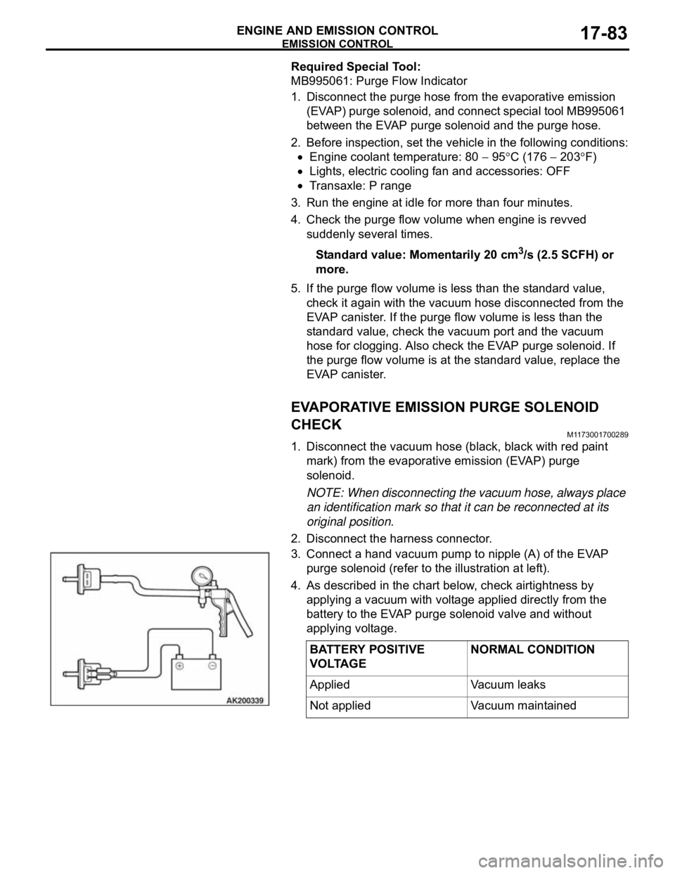
3. Connect a hand vacuum pump to nipple (A) of the EVAP
purge solenoid (refer to the illustration at left).
4. As described in the chart below, check airtightness by
applying a vacuum with voltage applied directly from the
battery to the EVAP purge solenoid valve and without
applying voltage.
BATTERY POSITIVE
VOLTAGENORMAL CONDITION
Applied Vacuum leaks
Not applied Vacuum maintained