Page 1069 of 1500

BODY42-2
DOOR . . . . . . . . . . . . . . . . . . . . . . . . .42-23
GENERAL DESCRIPTION . . . . . .
42-23
CENTRAL DOOR LOCKING SYSTEM
DIAGNOSIS . . . . . . . . . . . . . . . . . . . . . . 42-23
POWER WINDOW DIAGNOSIS . . . . . . 42-23
DOOR DIAGNOSIS . . . . . . . . . . . . . . . . 42-23
INTRODUCTION TO GLASS AND DOOR
DIAGNOSIS . . . . . . . . . . . . . . . . . . . . . . 42-23
GLASS AND DOOR DIAGNOSTIC
TROUBLESHOOTING STRATEGY . . . 42-23
SYMPTOM CHART . . . . . . . . . . . . . . . . 42-24
SYMPTOM PROCEDURES . . . . . . . . . 42-24
HOW TO LOCATE WIND NOISE . . . . . 42-27
SPECIAL TOOLS. . . . . . . . . . . . . .42-28
ON-VEHICLE SERVICE. . . . . . . . .42-30
DOOR FIT ADJUSTMENT. . . . . . . . . . . 42-30
DOOR WINDOW GLASS ADJUSTMENT42-31
GLASS SLIDING MECHANISM CHECK
AND ADJUSTMENT . . . . . . . . . . . . . . . 42-32
POWER WINDOW TIMER FUNCTION
CHECK . . . . . . . . . . . . . . . . . . . . . . . . . 42-32
POWER WINDOW OPERATING
CURRENT CHECK . . . . . . . . . . . . . . . . 42-33
POWER WINDOW RELAY CHECK . . . 42-33
CIRCUIT BREAKER (INCORPORATED IN
THE POWER WINDOW MOTOR)
INSPECTION . . . . . . . . . . . . . . . . . . . . . 42-34
POWER WINDOW CHECK . . . . . . . . . . 42-34
CENTRAL DOOR LOCKING SYSTEM
INSPECTION . . . . . . . . . . . . . . . . . . . . . 42-34
DOOR OUTSIDE HANDLE PLAY CHECK42-35
DOOR INSIDE HANDLE PLAY CHECK 42-35
DOOR ASSEMBLY . . . . . . . . . . . .42-37
REMOVAL AND INSTALLATION . . . . . 42-37
INSPECTION . . . . . . . . . . . . . . . . . . . . . 42-38
DOOR GLASS AND REGULATOR42-39
REMOVAL AND INSTALLATION . . . . . 42-39
INSPECTION . . . . . . . . . . . . . . . . . . . . . 42-43
DOOR HANDLE AND LATCH . . . .42-46
REMOVAL AND INSTALLATION . . . . . 42-46
INSPECTION . . . . . . . . . . . . . . . . . . . . . 42-49
WINDOW GLASS RUNCHANNEL
AND DOOR OPENING
WEATHERSTRIP . . . . . . . . . . . . . .
42-52
REMOVAL AND INSTALLATION . . . . . . 42-52
TRUNK LID. . . . . . . . . . . . . . . . 42-60
TRUNK LID DIAGNOSIS . . . . . . . .
42-60
INTRODUCTION TO TRUNK LID
DIAGNOSIS . . . . . . . . . . . . . . . . . . . . . . 42-60
TRUNK LID DIAGNOSTIC
TROUBLESHOOTING STRATEGY . . . . 42-60
SYMPTOM CHART . . . . . . . . . . . . . . . . 42-60
SYMPTOM PROCEDURES . . . . . . . . . . 42-60
ON-VEHICLE SERVICE . . . . . . . . .42-61
ADJUSTMENT OF CLEARANCE
AROUND TRUNK LID . . . . . . . . . . . . . . 42-61
TRUNK LID LATCH ADJUSTMENT. . . . 42-61
TRUNK LID HEIGHT ADJUSTMENT . . . 42-62
TRUNK LID . . . . . . . . . . . . . . . . . . .42-63
REMOVAL AND INSTALLATION . . . . . . 42-63
INSPECTION . . . . . . . . . . . . . . . . . . . . . 42-65
KEYLESS ENTRY SYSTEM 42-67
GENERAL DESCRIPTION . . . . . . .
42-67
KEYLESS ENTRY SYSTEM
DIAGNOSIS . . . . . . . . . . . . . . . . . .
42-68
SPECIAL TOOL . . . . . . . . . . . . . . .42-68
ON-VEHICLE SERVICE . . . . . . . . .42-69
TRANSMITTER BATTERY CHECK . . . . 42-69
HOW TO REPLACE THE TRANSMITTER
BATTERY . . . . . . . . . . . . . . . . . . . . . . . . 42-70
KEYLESS ENTRY SYSTEM INSPECTION42-71
KEYLESS ENTRY SYSTEM TIMER LOCK
FUNCTION INSPECTION . . . . . . . . . . . 42-71
ENABLING/DISABLING THE
ANSWERBACK FUNCTION . . . . . . . . . 42-72
HOW TO REGISTER SECRET CODE . 42-73
Continued on next page
Page 1127 of 1500

TRUNK LID
BODY42-60
TRUNK LID
TRUNK LID DIAGNOSIS
INTRODUCTION TO TRUNK LID DIAGNOSISM1421005800374
Difficult locking and unlocking, uneven clearance and
height, and wind noise from the trunk lid may be
caused by improper adjustment of the trunk lid.
TRUNK LID DIAGNOSTIC TROUBLESHOOTING STRATEGYM1421005900348
Use these steps to plan your diagnostic strategy. If
you follow them carefully, you will be sure that you
have exhausted most of the possible ways to find a
trunk lid fault.
1. Gather information from the customer.2. Verify that the condition described by the
customer exists.
3. Find the malfunction by following the Symptom
Chart.
4. Verify malfunction is eliminated.
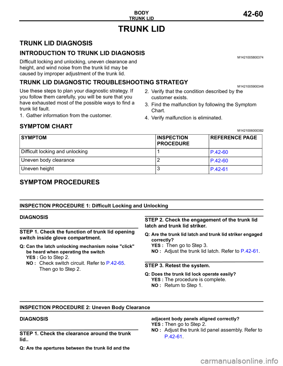
SYMPTOM CHARTM1421006000382
SYMPTOM PROCEDURES
INSPECTION PROCEDURE 1: Difficult Locking and Unlocking
DIAGNOSIS
STEP 1. Check the function of trunk lid opening
switch inside glove compartment.
Q: Can the latch unlocking mechanism noise "click"
be heard when operating the switch
YES :
Go to Step 2.
NO : Check switch circuit. Refer to P.42-65.
Then go to Step 2.
STEP 2. Check the engagement of the trunk lid
latch and trunk lid striker.
Q: Are the trunk lid latch and trunk lid striker engaged
correctly?
YES :
Then go to Step 3.
NO : Adjust the trunk lid latch. Refer to P.42-61.
STEP 3. Retest the system.
Q: Does the trunk lid lock operate easily?
YES :
The procedure is complete.
NO : Return to Step 1.
INSPECTION PROCEDURE 2: Uneven Body Clearance
DIAGNOSIS
STEP 1. Check the clearance around the trunk
lid..
Q: Are the apertures between the trunk lid and the adjacent body panels aligned correctly?
YES :
Then go to Step 2.
NO : Adjust the trunk lid panel assembly. Refer to
P.42-61. SYMPTOM INSPECTION
PROCEDUREREFERENCE PAGE
Difficult locking and unlocking 1
P.42-60
Uneven body clearance 2
P.42-60
Uneven height 3
P.42-61
Page 1128 of 1500

TRUNK LID
BODY42-61
STEP 2. Retest the system.
Q: Are the clearances between the body panels even?
YES :
The procedure is complete.
NO : Return to Step 1.
INSPECTION PROCEDURE 3: Uneven Height
DIAGNOSIS
STEP 1. Check the trunk lid bumper height.
Q: Is the trunk lid bumper height proper?
YES :
Then go to Step 2.
NO : Adjust the trunk lid bumper. Refer to
P.42-62.
STEP 2. Retest the system.
Q: Are the trunk lid and body height even?
YES :
The procedure is complete.
NO : Return to Step 1.
ON-VEHICLE SERVICE
ADJUSTMENT OF CLEARANCE AROUND TRUNK
LID
M1421008100040
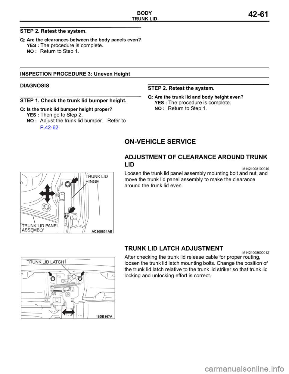
Loosen the trunk lid panel assembly mounting bolt and nut, and
move the trunk lid panel assembly to make the clearance
around the trunk lid even.
TRUNK LID LATCH ADJUSTMENTM1421008600012
After checking the trunk lid release cable for proper routing,
loosen the trunk lid latch mounting bolts. Change the position of
the trunk lid latch relative to the trunk lid striker so that trunk lid
locking and unlocking effort is correct.
Page 1129 of 1500
TRUNK LID
BODY42-62
TRUNK LID HEIGHT ADJUSTMENTM1421008300044
Turn each trunk lid damper to achieve the height shown in the
drawing is reached. If the trunk lid panel height on one side is
different from that on the other side (even after the trunk lid
dampers have been adjusted to the height indicated in the
drawing), turn the trunk lid damper(s) slightly to make fine
adjustments to the trunk lid panel height.
NOTE: When the damper is new, one full turn of the trunk lid
damper changes the height approximately 3 mm. Turn it clock-
wise to reduce height. Turn it counterclockwise to increase
height.
Page 1130 of 1500
TRUNK LID
BODY42-63
TRUNK LID
REMOVAL AND INSTALLATIONM1421002200191
Do not disassemble or throw the trunk lid gas spring into fire.
Punch a hole in the trunk lid gas spring before disposal to release the gas inside.
Ensure the trunk lid gas spring piston rod does not come into contact with foreign material.
Post-installation Operation
Adjustment of Clearance Around Trunk Lid (Refer to
P.42-61).
Trunk Lid Latch Adjustment (Refer to P.42-61).
Trunk Lid Height Adjustment (Refer to P.42-62).
Page 1131 of 1500

TRUNK LID
BODY42-64
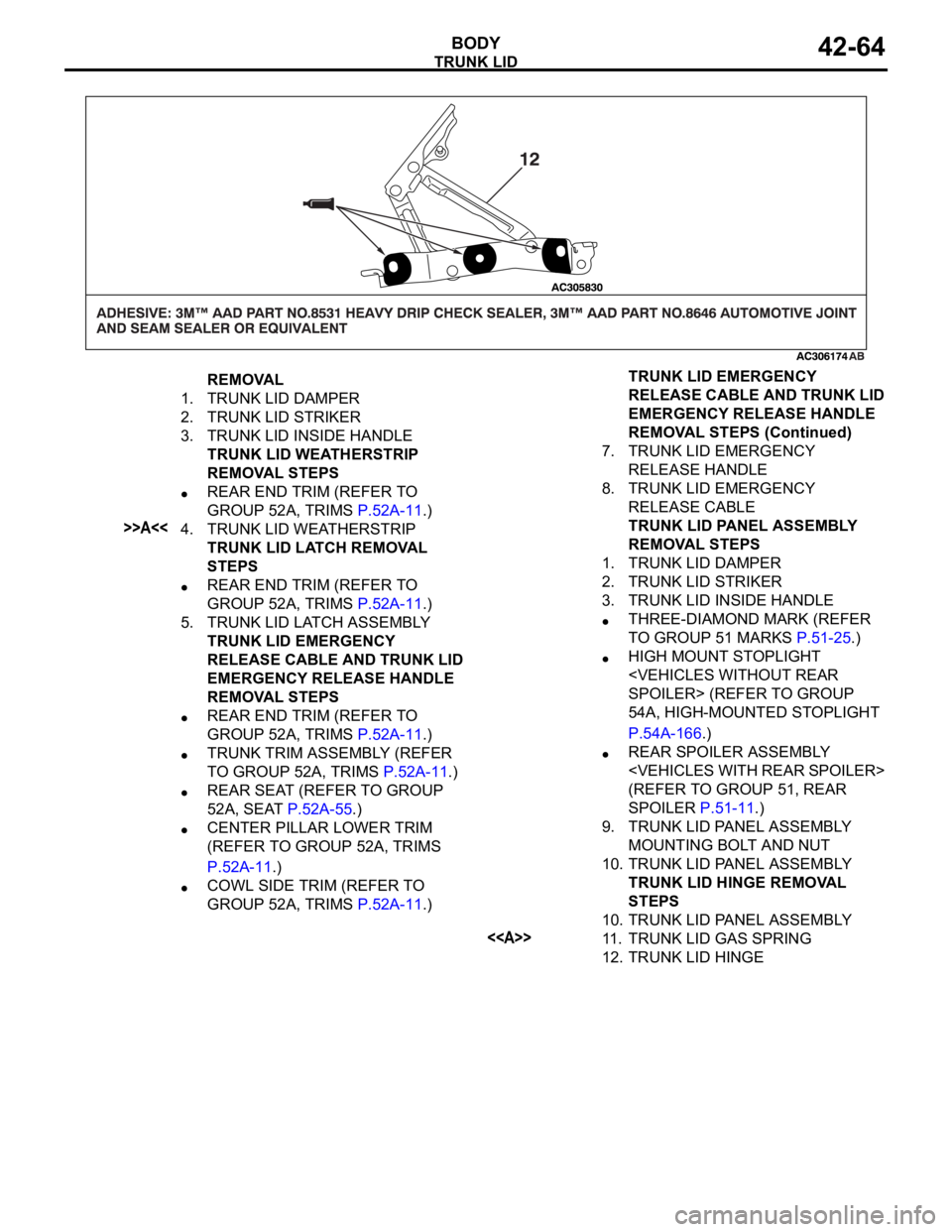
REMOVAL
1. TRUNK LID DAMPER
2. TRUNK LID STRIKER
3. TRUNK LID INSIDE HANDLE
TRUNK LID WEATHERSTRIP
REMOVAL STEPS
REAR END TRIM (REFER TO
GROUP 52A, TRIMS P.52A-11.)
>>A<<4. TRUNK LID WEATHERSTRIP
TRUNK LID LATCH REMOVAL
STEPS
REAR END TRIM (REFER TO
GROUP 52A, TRIMS P.52A-11.)
5. TRUNK LID LATCH ASSEMBLY
TRUNK LID EMERGENCY
RELEASE CABLE AND TRUNK LID
EMERGENCY RELEASE HANDLE
REMOVAL STEPS
REAR END TRIM (REFER TO
GROUP 52A, TRIMS P.52A-11.)
TRUNK TRIM ASSEMBLY (REFER
TO GROUP 52A, TRIMS P.52A-11.)
REAR SEAT (REFER TO GROUP
52A, SEAT P.52A-55.)
CENTER PILLAR LOWER TRIM
(REFER TO GROUP 52A, TRIMS
P.52A-11.)
COWL SIDE TRIM (REFER TO
GROUP 52A, TRIMS P.52A-11.)7. TRUNK LID EMERGENCY
RELEASE HANDLE
8. TRUNK LID EMERGENCY
RELEASE CABLE
TRUNK LID PANEL ASSEMBLY
REMOVAL STEPS
1. TRUNK LID DAMPER
2. TRUNK LID STRIKER
3. TRUNK LID INSIDE HANDLE
THREE-DIAMOND MARK (REFER
TO GROUP 51 MARKS P.51-25.)
HIGH MOUNT STOPLIGHT
SPOILER> (REFER TO GROUP
54A, HIGH-MOUNTED STOPLIGHT
P.54A-166.)
REAR SPOILER ASSEMBLY
(REFER TO GROUP 51, REAR
SPOILER P.51-11.)
9. TRUNK LID PANEL ASSEMBLY
MOUNTING BOLT AND NUT
10. TRUNK LID PANEL ASSEMBLY
TRUNK LID HINGE REMOVAL
STEPS
10. TRUNK LID PANEL ASSEMBLY
<>11. TRUNK LID GAS SPRING
12. TRUNK LID HINGETRUNK LID EMERGENCY
RELEASE CABLE AND TRUNK LID
EMERGENCY RELEASE HANDLE
REMOVAL STEPS (Continued)
Page 1132 of 1500
Page 1133 of 1500
TRUNK LID
BODY42-66
TRUNK LID LATCH SWITCH CONTINUITY CHECK
LEVER POSITION TESTER
CONNECTIONSPECIFIED
CONDITION
ON (Latch open) 2
Ground Less than 2 ohms
OFF (Latch shut) 2
Ground Open circuit