2005 MITSUBISHI 380 engine coolant
[x] Cancel search: engine coolantPage 1223 of 1500
GENERAL00-2
MAINTENANCE SERVICE . . . . . . . .00-37
1. FUEL SYSTEM (TANK, PIPE LINE AND
CONNECTION, AND FUEL TANK FILLER
TUBE CAP) (CHECK FOR LEAKS) . . . . . . 00-37
2. FUEL HOSES (CHECK CONDITION) . . 00-37
3. AIR CLEANER FILTER (REPLACE). . . . 00-37
4. EVAPORATIVE EMISSION SYSTEM
(EXCEPT EVAPORATIVE EMISSION
CANISTER) (CHECK FOR CLOGGING) . . 00-37
5. SPARK PLUGS (REPLACE). . . . . . . . . . 00-38
7. TIMING BELT (REPLACE) . . . . . . . . . . . 00-38
8. DRIVE BELTS (FOR ALTERNATOR, POWER
STEERING PUMP AND AIR CONDITIONING)
(CHECK) . . . . . . . . . . . . . . . . . . . . . . . . . . . 00-39
9. EXHAUST SYSTEM (CONNECTIONS
PORTION OF MUFFLER, MUFFLER PIPES
AND CONVERTER HEAT SHIELDS) (CHECK
AND SERVICE AS REQUIRED) . . . . . . . . . 00-44
10. ENGINE OIL (CHANGE) . . . . . . . . . . . . 00-4411. ENGINE OIL FILTER (REPLACE) . . . . 00-44
12. TRANSMISSION FLUID . . . . . . . . . . . . 00-45
13. ENGINE COOLANT (CHANGE) . . . . . . 00-47
14. COOLANT HOSES (RADIATOR HOSE,
HEATER HOSE) (INSPECT). . . . . . . . . . . . 00-49
15. DISC BRAKE PADS, ROTORS
(INSPECT FOR WEAR) . . . . . . . . . . . . . . . 00-49
16. BRAKE HOSES (CHECK FOR
DETERIORATION OR LEAKS) . . . . . . . . . . 00-49
17. BALL JOINT AND STEERING LINKAGE
SEALS (INSPECT FOR GREASE LEAKS
AND DAMAGE) . . . . . . . . . . . . . . . . . . . . . . 00-50
18. DRIVE SHAFT BOOTS (INSPECT FOR
GREASE LEAKS AND DAMAGE) . . . . . . . . 00-50
19. SUSPENSION SYSTEM (INSPECT FOR
LOOSENESS AND DAMAGE) . . . . . . . . . . 00-51
20. SRS AIR BAG (INSPECT FOR SRS
SYSTEM). . . . . . . . . . . . . . . . . . . . . . . . . . . 00-51
21. TYRES (ROTATE). . . . . . . . . . . . . . . . . 00-58
Page 1245 of 1500
PRECAUTIONS BEFORE SERVICE
GENERAL00-24
SERVICING ELECTRICAL SYSTEMM1001011900057
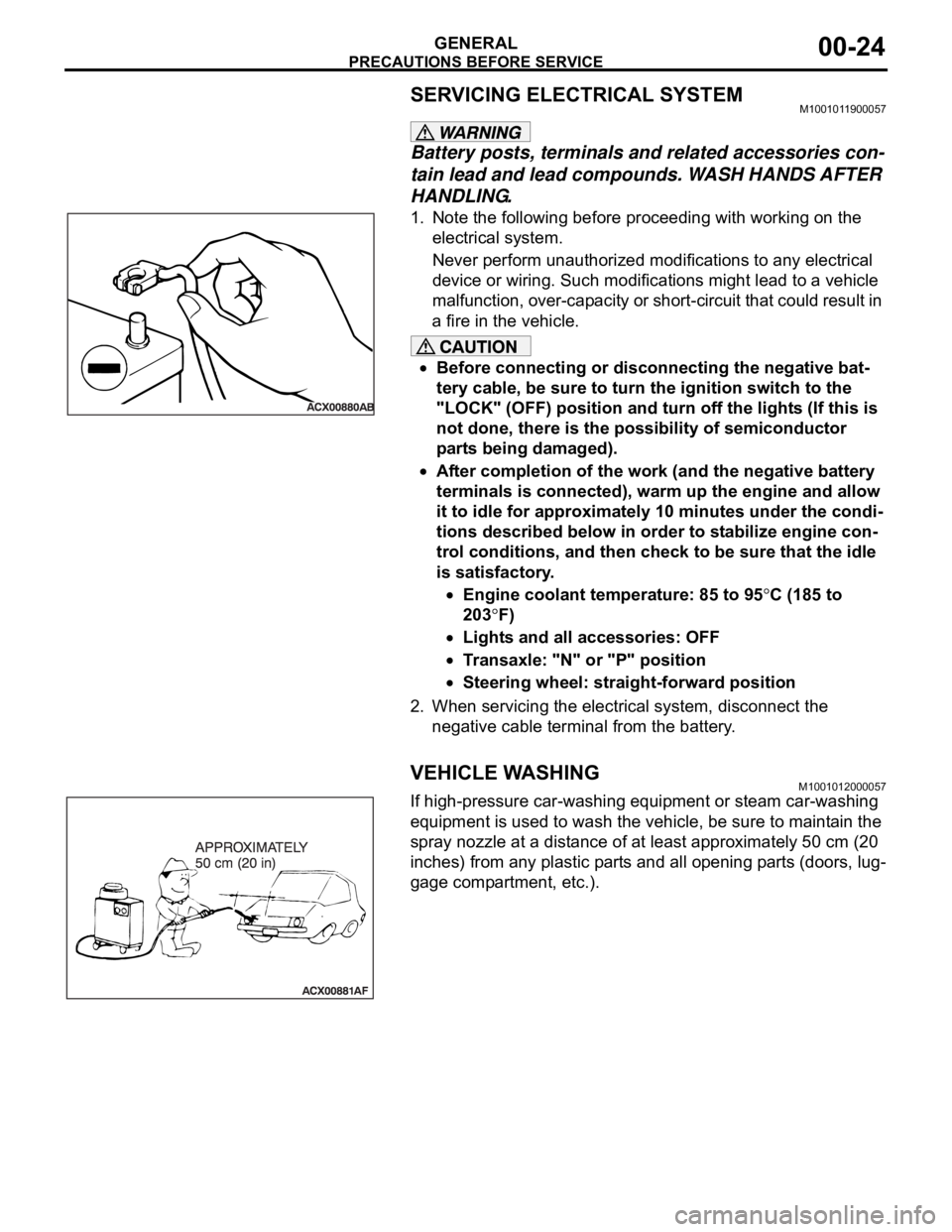
Battery posts, terminals and related accessories con-
tain lead and lead compounds. WASH HANDS AFTER
HANDLING.
1. Note the following before proceeding with working on the
electrical system.
Never perform unauthorized modifications to any electrical
device or wiring. Such modifications might lead to a vehicle
malfunction, over-capacity or short-circuit that could result in
a fire in the vehicle.
Before connecting or disconnecting the negative bat-
tery cable, be sure to turn the ignition switch to the
"LOCK" (OFF) position and turn off the lights (If this is
not done, there is the possibility of semiconductor
parts being damaged).
After completion of the work (and the negative battery
terminals is connected), warm up the engine and allow
it to idle for approximately 10 minutes under the condi-
tions described below in order to stabilize engine con-
trol conditions, and then check to be sure that the idle
is satisfactory.
Engine coolant temperature: 85 to 95C (185 to
203
F)
Lights and all accessories: OFF
Transaxle: "N" or "P" position
Steering wheel: straight-forward position
2. When servicing the electrical system, disconnect the
negative cable terminal from the battery.
VEHICLE WASHINGM1001012000057
If high-pressure car-washing equipment or steam car-washing
equipment is used to wash the vehicle, be sure to maintain the
spray nozzle at a distance of at least approximately 50 cm (20
inches) from any plastic parts and all opening parts (doors, lug-
gage compartment, etc.).
Page 1256 of 1500

RECOMMENDED LUBRICANTS AND LUBRICANT CAPACITIES TABLE
GENERAL00-35
RECOMMENDED LUBRICANTS AND LUBRICANT
CAPACITIES TABLE
M1001001300504
RECOMMENDED LUBRICANTS
LUBRICANT CAPACITY TABLE
<3.8L ENGINE>LUBRICANT SPECIFICATION
Engine oil Engine oils conforming to ACEA A1, A2 or A3 and
AP1 SG or higher
AutomaticTransmission fluid Genuine Mitsubishi Motors ATF-SP III
Manual Transmission fluid Genuine Mitsubishi Motors MTF
Power steering fluid ATF DEXRON III or DEXRON II
Brakes fluid Conforming to DOT 3 or DOT 4
Engine coolant Genuine Mitsubishi Motors coolant
Refrigerant (air conditioning) HFC-134a
DESCRIPTION SPECIFICATION
Engine oil (Litres) Oil pan (excluding oil filter) 4.0
Oil filter 0.3
Engine coolant (Litres) 8.7
Automatic Transmission fluid (Litres) 8.4
Manual Transmission fluid (Litres) 2.8
Power steering fluid (Litres) 1.2
Fuel tank (Litres) 67.0
Washer fluid (Litres) 5.0
Refrigerant (air conditioning) (grams) 435g - 475g
Page 1257 of 1500
RECOMMENDED LUBRICANTS AND LUBRICANT CAPACITIES TABLE
GENERAL00-36
SELECTION OF COOLANT
.
COOLANT
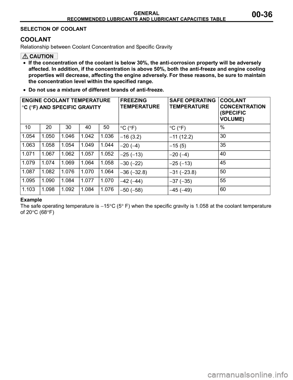
Relationship between Coolant Concentration and Specific Gravity
If the concentration of the coolant is below 30%, the anti-corrosion property will be adversely
affected. In addition, if the concentration is above 50%, both the anti-freeze and engine cooling
properties will decrease, affecting the engine adversely. For these reasons, be sure to maintain
the concentration level within the specified range.
Do not use a mixture of different brands of anti-freeze.
Example
The safe operating temperature is
15C (5 F) when the specific gravity is 1.058 at the coolant temperature
of 20
C (68F) ENGINE COOLANT TEMPERATURE
C (F) AND SPECIFIC GRAVITYFREEZING
TEMPERATURESAFE OPERATING
TEMPERATURECOOLANT
CONCENTRATION
(SPECIFIC
VOLUME)
10 20 30 40 50
C (F)C (F)%
1.054 1.050 1.046 1.042 1.036
16 (3.2)11 ( 1 2 . 2 )30
1.063 1.058 1.054 1.049 1.044
20 (4)15 (5)35
1.071 1.067 1.062 1.057 1.052
25 (13)20 (4)40
1.079 1.074 1.069 1.064 1.058
30 (22)25 (13)45
1.087 1.082 1.076 1.070 1.064
36 (32.8)31 (23.8)50
1.095 1.090 1.084 1.077 1.070
42 (44)37 (35)55
1.103 1.098 1.092 1.084 1.076
50 (58)45 (49)60
Page 1265 of 1500
MAINTENANCE SERVICE
GENERAL00-44
8. EXHAUST SYSTEM (CONNECTIONS PORTION
OF MUFFLER, MUFFLER PIPES AND
CONVERTER HEAT SHIELDS) (CHECK AND
SERVICE AS REQUIRED)
M1001005800299
1. Check for holes and exhaust gas leaks due to damage,
corrosion, etc.
2. Check the joints and connections for looseness and exhaust
gas leaks.
3. Check the rubber hangers and brackets for damage.
9. ENGINE OIL (CHANGE)M1001002600360
Use the specified oil. (Refer to P.00-35.)
Use care as oil could be hot.
1. After warming up the engine, remove the oil filler cap.
2. Remove the drain plug to allow the engine oil to drain.
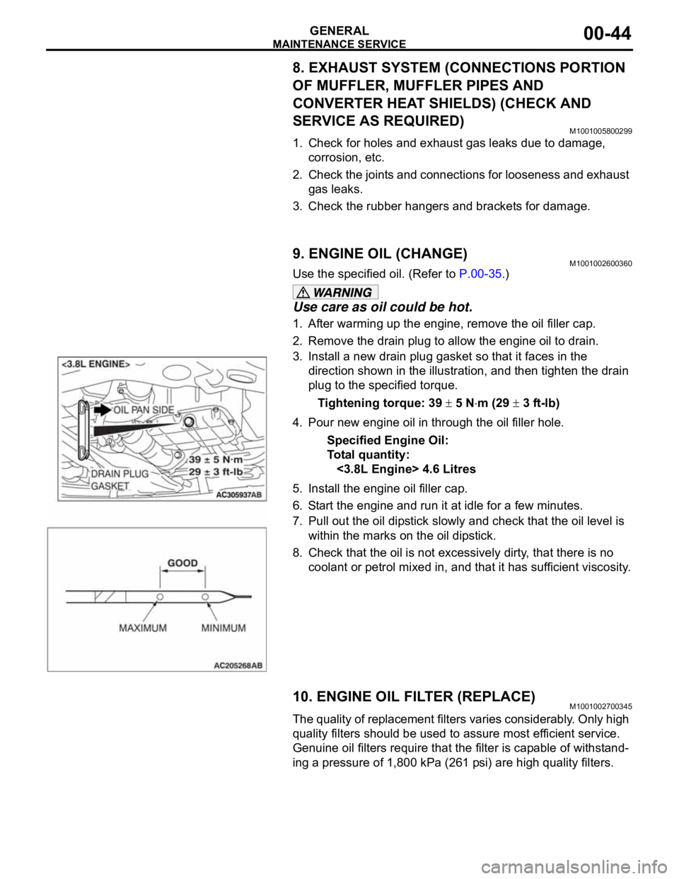
3. Install a new drain plug gasket so that it faces in the
direction shown in the illustration, and then tighten the drain
plug to the specified torque.
Tightening torque: 39
5 Nm (29 3 ft-lb)
4. Pour new engine oil in through the oil filler hole.
Specified Engine Oil:
To ta l q u a n t i t y :
<3.8L Engine> 4.6 Litres
5. Install the engine oil filler cap.
6. Start the engine and run it at idle for a few minutes.
7. Pull out the oil dipstick slowly and check that the oil level is
within the marks on the oil dipstick.
8. Check that the oil is not excessively dirty, that there is no
coolant or petrol mixed in, and that it has sufficient viscosity.
10. ENGINE OIL FILTER (REPLACE)M1001002700345
The quality of replacement filters varies considerably. Only high
quality filters should be used to assure most efficient service.
Genuine oil filters require that the filter is capable of withstand-
ing a pressure of 1,800 kPa (261 psi) are high quality filters.
.
Page 1268 of 1500
MAINTENANCE SERVICE
GENERAL00-47
6. Securely insert the dipstick.
NOTE: The transmission fluid should always be replaced
under the following conditions:
.
When troubleshooting the transaxle.
When overhauling the transaxle.
When the transmission fluid is noticeably dirty or burnt
(driving under severe conditions).
TRANSMISSION FLUID CHANGE
Refer to GROUP 23A, Automatic Transmission - On-vehicle
Service P.23A-296.
12. ENGINE COOLANT (CHANGE)M1001003100357
Check the cooling system parts such as the radiator, heater
and oil cooler hoses, thermostat and their connections for leak-
age and damage.
.
CHANGING COOLANT
1. Set the temperature control knob to the "HOT" position.
2. Run the engine until the engine coolant warms, and then
stop the engine.
When removing the radiator cap, use care to avoid
contact with hot coolant or steam. Place a shop towel
over the cap and turn the cap counterclockwise a lit-
tle to let the pressure escape through the vinyl tube.
After relieving the steam pressure, remove the cap by
slowly turning it counterclockwise.
3. Drain the water from the radiator, heater core and engine
after unplugging the radiator drain plug and removing the
radiator cap.
Page 1269 of 1500
MAINTENANCE SERVICE
GENERAL00-48
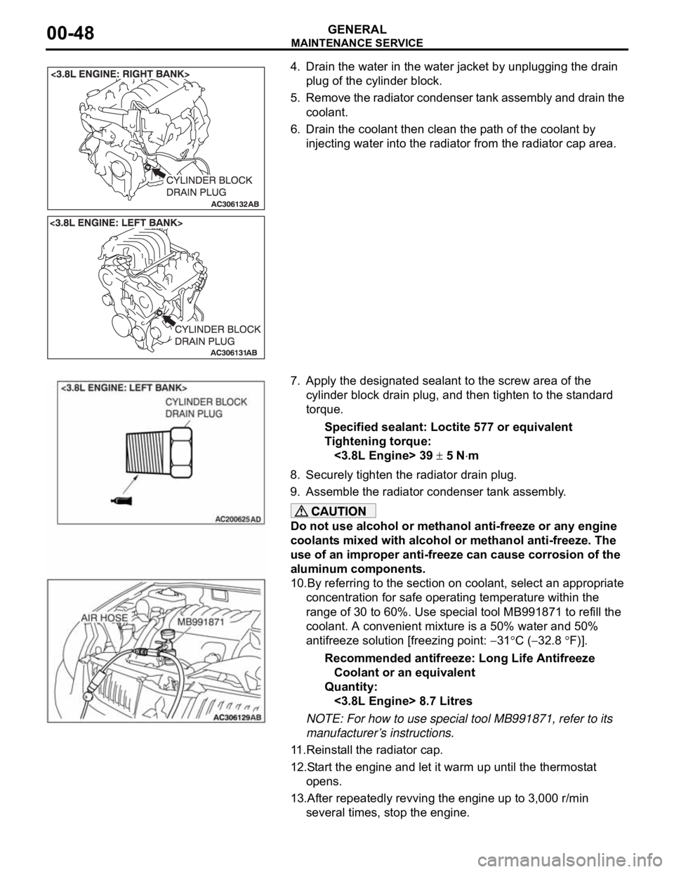
4. Drain the water in the water jacket by unplugging the drain
plug of the cylinder block.
5. Remove the radiator condenser tank assembly and drain the
coolant.
6. Drain the coolant then clean the path of the coolant by
injecting water into the radiator from the radiator cap area.
7. Apply the designated sealant to the screw area of the
cylinder block drain plug, and then tighten to the standard
torque.
Specified sealant: Loctite 577 or equivalent
Tightening torque:
<3.8L Engine> 39
5 Nm
8. Securely tighten the radiator drain plug.
9. Assemble the radiator condenser tank assembly.
Do not use alcohol or methanol anti-freeze or any engine
coolants mixed with alcohol or methanol anti-freeze. The
use of an improper anti-freeze can cause corrosion of the
aluminum components.
10.By referring to the section on coolant, select an appropriate
concentration for safe operating temperature within the
range of 30 to 60%. Use special tool MB991871 to refill the
coolant. A convenient mixture is a 50% water and 50%
antifreeze solution [freezing point:
31C (32.8 F)].
Recommended antifreeze: Long Life Antifreeze
Coolant or an equivalent
Quantity:
<3.8L Engine> 8.7 Litres
NOTE: For how to use special tool MB991871, refer to its
manufacturer’s instructions.
11.Reinstall the radiator cap.
12.Start the engine and let it warm up until the thermostat
opens.
13.After repeatedly revving the engine up to 3,000 r/min
several times, stop the engine.
Page 1270 of 1500
MAINTENANCE SERVICE
GENERAL00-49
14.Remove the radiator cap after the engine has cooled, and
pour in coolant up to the brim. Reinstall the cap.
Do not overfill the radiator condenser tank assembly.
15.Add coolant to the radiator condenser tank assembly
between the "FULL" and "LOW" mark if necessary.
13. COOLANT HOSES (RADIATOR HOSE,
HEATER HOSE) (INSPECT)
M1001009700034
Inspect the surface of radiator hoses and heater hoses for heat
and mechanical damage. Hard and brittle rubber, cracking,
tears, cuts, abrasions and excessive swelling indicate deterio-
ration of the rubber.
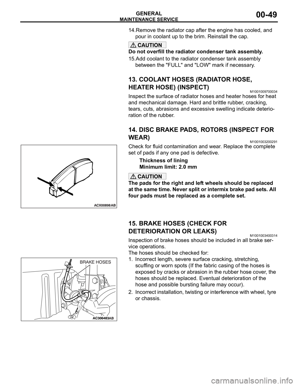
14. DISC BRAKE PADS, ROTORS (INSPECT FOR
WEAR)
M1001003200291
Check for fluid contamination and wear. Replace the complete
set of pads if any one pad is defective.
Thickness of lining
Minimum limit: 2.0 mm
The pads for the right and left wheels should be replaced
at the same time. Never split or intermix brake pad sets. All
four pads must be replaced as a complete set.
15. BRAKE HOSES (CHECK FOR
DETERIORATION OR LEAKS)
M1001003400314
Inspection of brake hoses should be included in all brake ser-
vice operations.
The hoses should be checked for:
1. Incorrect length, severe surface cracking, stretching,
scuffing or worn spots (If the fabric casing of the hoses is
exposed by cracks or abrasion in the rubber hose cover, the
hoses should be replaced. Eventual deterioration of the
hose and possible bursting failure may occur).
2. Incorrect installation, twisting or interference with wheel, tyre
or chassis.