Page 918 of 1500
ENGINE COOLING DIAGNOSIS
ENGINE COOLING14-3
SYMPTOM CHARTM1141005600393
SYMPTOM PROCEDURES
INSPECTION PROCEDURE 1: Coolant Leak
DIAGNOSIS
STEP 1. Check for coolant leaks.
When pressure testing the cooling system, slowly
release cooling system pressure to avoid being
burned by hot coolant.
Be sure to completely clean away any moisture from
the places checked.
When the tester is removed, be careful not to spill any
coolant.
When installing and removing the tester and when test-
ing, be careful not to deform the filler neck of the radia-
tor.
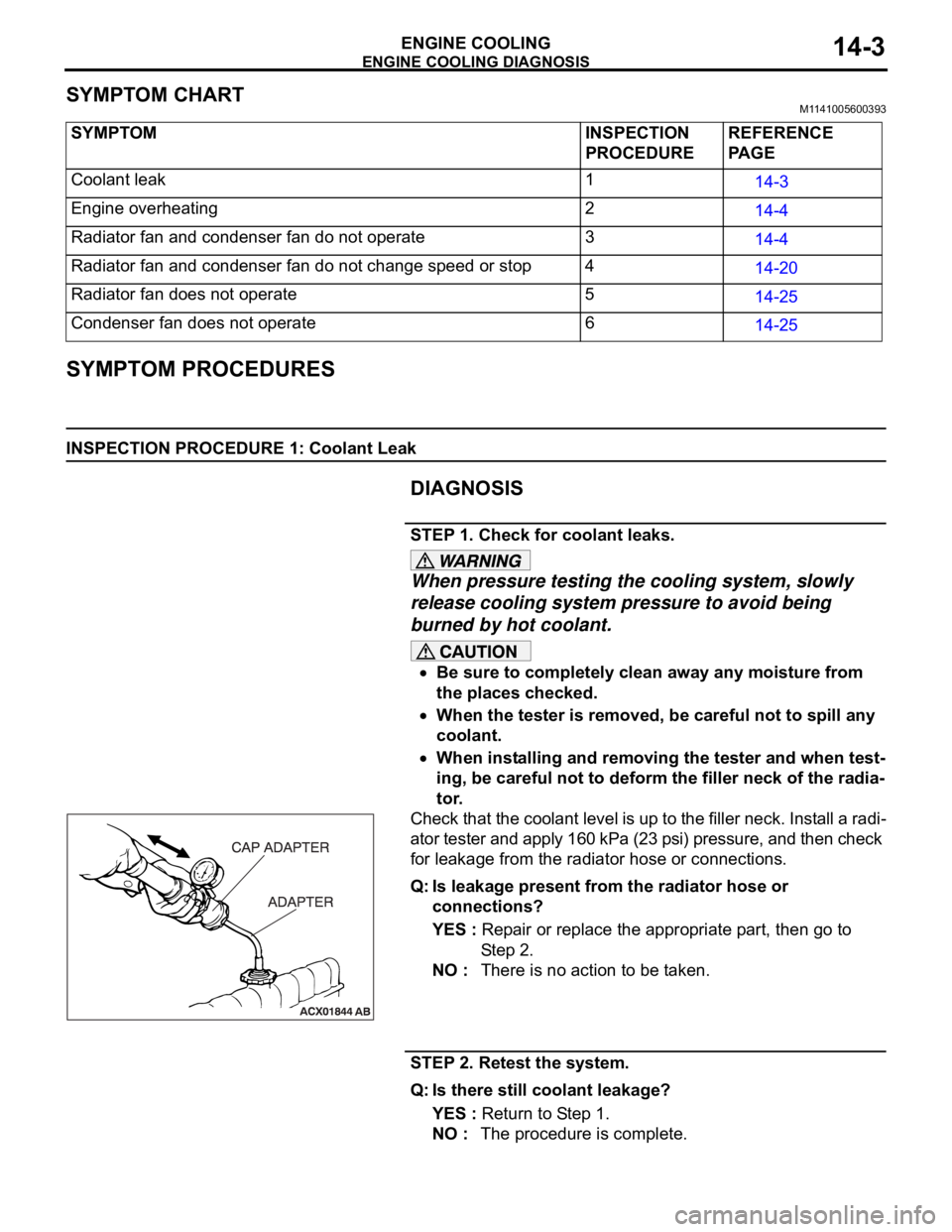
Check that the coolant level is up to the filler neck. Install a radi-
ator tester and apply 160 kPa (23 psi) pressure, and then check
for leakage from the radiator hose or connections.
Q: Is leakage present from the radiator hose or
connections?
YES : Repair or replace the appropriate part, then go to
St e p 2 .
NO : There is no action to be taken.
STEP 2. Retest the system.
Q: Is there still coolant leakage?
YES : Return to Step 1.
NO : The procedure is complete. SYMPTOM INSPECTION
PROCEDUREREFERENCE
PA G E
Coolant leak 1
14-3
Engine overheating 2
14-4
Radiator fan and condenser fan do not operate 3
14-4
Radiator fan and condenser fan do not change speed or stop 4
14-20
Radiator fan does not operate 5
14-25
Condenser fan does not operate 6
14-25
Page 919 of 1500
ENGINE COOLING DIAGNOSIS
ENGINE COOLING14-4
INSPECTION PROCEDURE 2: Engine Overheating
DIAGNOSIS
STEP 1. Remove the radiator cap and check for coolant
contamination.
Q: Is the coolant contaminated with rust and oil?
YES : Replace it. Refer to P.14-27.
NO : There is no action to be taken. Go to Step 2.
STEP 2. Check the radiator cap valve opening pressure.
NOTE: Be sure that the cap is clean before testing. Rust or
other foreign material on the cap seal will cause an improper
reading.
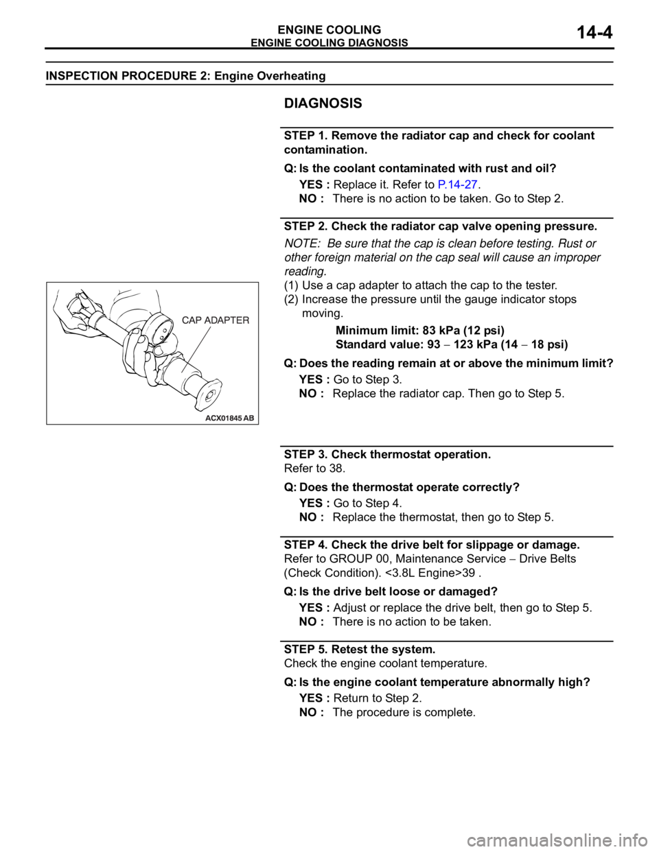
(1) Use a cap adapter to attach the cap to the tester.
(2) Increase the pressure until the gauge indicator stops
moving.
Minimum limit: 83 kPa (12 psi)
Standard value: 93
123 kPa (14 18 psi)
Q: Does the reading remain at or above the minimum limit?
YES : Go to Step 3.
NO : Replace the radiator cap. Then go to Step 5.
STEP 3. Check thermostat operation.
Refer to 38.
Q: Does the thermostat operate correctly?
YES : Go to Step 4.
NO : Replace the thermostat, then go to Step 5.
STEP 4. Check the drive belt for slippage or damage.
Refer to GROUP 00, Maintenance Service
Drive Belts
(Check Condition). <3.8L Engine>39 .
Q: Is the drive belt loose or damaged?
YES : Adjust or replace the drive belt, then go to Step 5.
NO : There is no action to be taken.
STEP 5. Retest the system.
Check the engine coolant temperature.
Q: Is the engine coolant temperature abnormally high?
YES : Return to Step 2.
NO : The procedure is complete.
Page 941 of 1500
ON-VEHICLE SERVICE
ENGINE COOLING14-26
DIAGNOSIS
STEP 1. Check the condenser fan motor.
Condenser fan motor check. (Refer to GROUP 55, Condenser
and Condenser Fan Motor.
Q: Is the condenser fan motor in good condition?
YES : Go to Step 2.
NO : Replace the condenser fan motor, then go to Step 3.
STEP 2. Check the fan controller.
Refer to 29.
Q: Is the fan controller in good condition?
YES : Go to Step 3.
NO : Replace the fan motor and fan controller (Refer to
14-25). Then go to Step 3.
STEP 3. Check the symptoms.
Q: Do the condenser fan operate?
YES : This symptom is complete.
NO : Return to Step 1.
ON-VEHICLE SERVICE
ENGINE COOLANT LEAK CHECKM1141001000333
When pressure testing the cooling system, slowly
release cooling system pressure to avoid getting
burned by hot coolant.
Be sure to completely clean away any moisture from
the places checked.
When the tester is taken out, be careful not to spill any
coolant.
Be careful when installing and removing the tester and
when testing not to deform the filler neck of the radia-
tor.
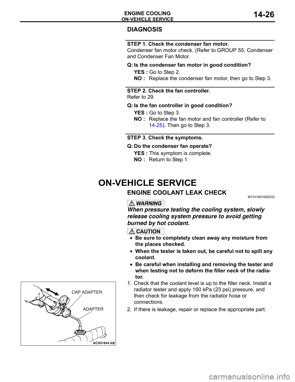
1. Check that the coolant level is up to the filler neck. Install a
radiator tester and apply 160 kPa (23 psi) pressure, and
then check for leakage from the radiator hose or
connections.
2. If there is leakage, repair or replace the appropriate part.
Page 942 of 1500
ON-VEHICLE SERVICE
ENGINE COOLING14-27
RADIATOR CAP PRESSURE CHECKM1141001300419
NOTE: Be sure that the cap is clean before testing. Rust or
other foreign material on the cap seal will cause an improper
reading.
1. Use a cap adapter to attach the cap to the tester.
2. Increase the pressure until the indicator of the gauge stops
moving.
Minimum limit: 83 kPa (12 psi)
Standard value: 93
123 kPa (14 18 psi)
3. Replace the radiator cap if the reading does not remain at or
above the limit.
ENGINE COOLANT REPLACEMENTM1141001200478
When removing the radiator cap, use care to avoid
contact with hot coolant or steam. Place a shop towel
over the cap and turn the cap counterclockwise a lit-
tle to let the pressure escape through the vinyl tube.
After relieving the steam pressure, remove the cap by
slowly turning it counterclockwise.
1. Drain the water from the radiator, heater core and engine
after unplugging the radiator drain plug and removing the
radiator cap.
Page 943 of 1500
ON-VEHICLE SERVICE
ENGINE COOLING14-28
2. Drain the water in the water jacket by unplugging the drain
plug of the cylinder block.
3. Remove the radiator condenser tank assembly and drain the
coolant.
4. Drain the coolant then clean the path of the coolant by
injecting water into the radiator from the radiator cap area.
5. Apply the designated sealant to the screw area of the
cylinder block drain plug, and then tighten to the standard
torque.
Specified sealant: 3M
AAD Part No.8731 or equiva-
lent
Tightening torque:
39
5 Nm
6. Securely tighten the radiator drain plug.
7. Assemble the radiator condenser tank assembly.
Page 944 of 1500
ON-VEHICLE SERVICE
ENGINE COOLING14-29
Do not use alcohol or methanol anti-freeze or any
engine coolants mixed with alcohol or methanol
anti-freeze. The use of an improper anti-freeze can
cause corrosion of the aluminum components.
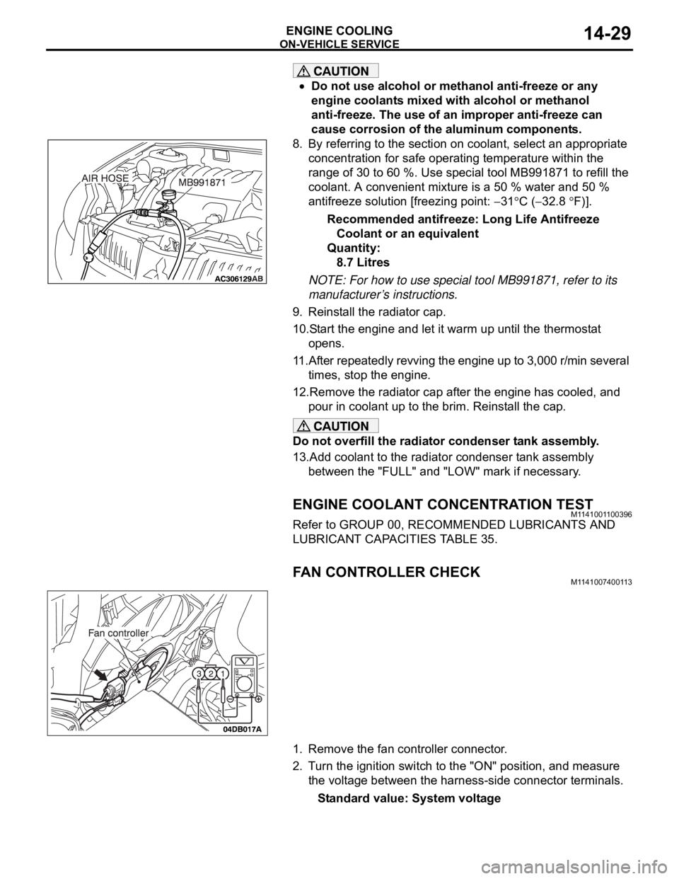
8. By referring to the section on coolant, select an appropriate
concentration for safe operating temperature within the
range of 30 to 60 %. Use special tool MB991871 to refill the
coolant. A convenient mixture is a 50 % water and 50 %
antifreeze solution [freezing point:
31C (32.8 F)].
Recommended antifreeze: Long Life Antifreeze
Coolant or an equivalent
Quantity:
8.7 Litres
NOTE: For how to use special tool MB991871, refer to its
manufacturer’s instructions.
9. Reinstall the radiator cap.
10.Start the engine and let it warm up until the thermostat
opens.
11.After repeatedly revving the engine up to 3,000 r/min several
times, stop the engine.
12.Remove the radiator cap after the engine has cooled, and
pour in coolant up to the brim. Reinstall the cap.
Do not overfill the radiator condenser tank assembly.
13.Add coolant to the radiator condenser tank assembly
between the "FULL" and "LOW" mark if necessary.
ENGINE COOLANT CONCENTRATION TESTM1141001100396
Refer to GROUP 00, RECOMMENDED LUBRICANTS AND
LUBRICANT CAPACITIES TABLE 35.
FAN CONTROLLER CHECKM1141007400113
1. Remove the fan controller connector.
2. Turn the ignition switch to the "ON" position, and measure
the voltage between the harness-side connector terminals.
Standard value: System voltage
Page 947 of 1500
Page 950 of 1500
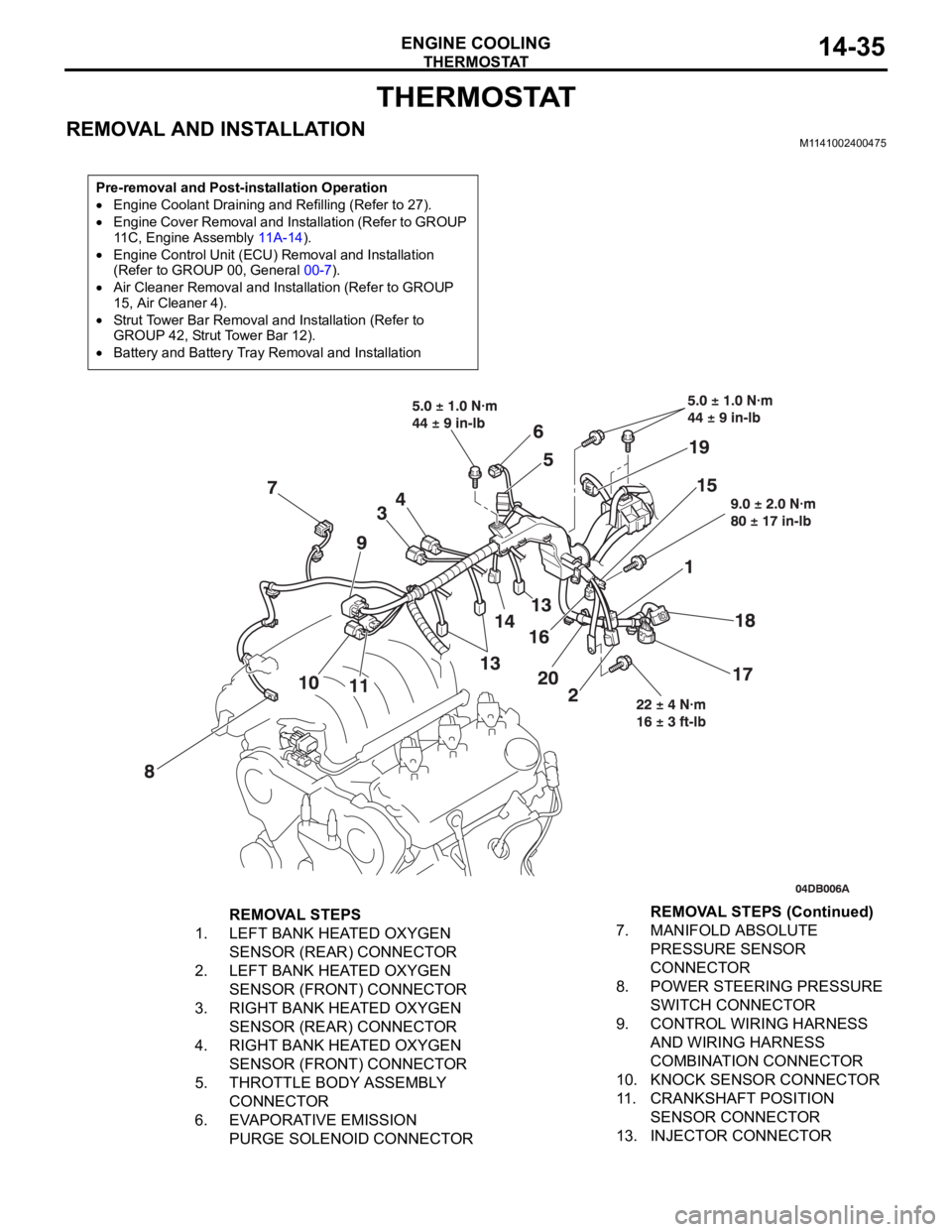
THERMOSTAT
ENGINE COOLING14-35
THERMOSTAT
REMOVAL AND INSTALLATIONM1141002400475
Pre-removal and Post-installation Operation
Engine Coolant Draining and Refilling (Refer to 27).
Engine Cover Removal and Installation (Refer to GROUP
11C, Engine Assembly 11A-14).
Engine Control Unit (ECU) Removal and Installation
(Refer to GROUP 00, General 00-7).
Air Cleaner Removal and Installation (Refer to GROUP
15, Air Cleaner 4).
Strut Tower Bar Removal and Installation (Refer to
GROUP 42, Strut Tower Bar 12).
Battery and Battery Tray Removal and Installation
REMOVAL STEPS
1. LEFT BANK HEATED OXYGEN
SENSOR (REAR) CONNECTOR
2. LEFT BANK HEATED OXYGEN
SENSOR (FRONT) CONNECTOR
3. RIGHT BANK HEATED OXYGEN
SENSOR (REAR) CONNECTOR
4. RIGHT BANK HEATED OXYGEN
SENSOR (FRONT) CONNECTOR
5. THROTTLE BODY ASSEMBLY
CONNECTOR
6. EVAPORATIVE EMISSION
PURGE SOLENOID CONNECTOR7. MANIFOLD ABSOLUTE
PRESSURE SENSOR
CONNECTOR
8. POWER STEERING PRESSURE
SWITCH CONNECTOR
9. CONTROL WIRING HARNESS
AND WIRING HARNESS
COMBINATION CONNECTOR
10. KNOCK SENSOR CONNECTOR
11. CRANKSHAFT POSITION
SENSOR CONNECTOR
13. INJECTOR CONNECTORREMOVAL STEPS (Continued)