Page 808 of 1500
AUTO A/C DIAGNOSIS
HEATER, AIR CONDITIONING AND VENTILATION55-107
STEP 4. Check the A/C pressure sensor.
(1) Assemble a gauge manifold on the high pressure service
valve.
(2) Disconnect the A/C pressure sensor connector and connect
special tool test harness MB991658 as shown in the
illustration.
(3) Turn ON the engine and then turn ON the air conditioner
switch.
(4) At this time, check to see that the voltage of A/C pressure
sensor terminal No. 2 reflects the specifications of the
figure.
NOTE: The allowance shall be defined as
5%.
Q: Is the A/C pressure sensor in good condition?
YES : Go to Step 5.
NO : Replace the A/C pressure sensor. Check that the air
conditioning works normally.
Page 822 of 1500

AUTO A/C DIAGNOSIS
HEATER, AIR CONDITIONING AND VENTILATION55-121
STEP 17. Check the defogger.
(1) Let the engine run at 2,000 r/min, and check the printed
heater with the battery fully charged.
(2) Turn on the defogger switch, and use a voltmeter to
measure the voltage in each printed heater at middle point
A on the rear window glass.
The value should be approximately 6 volts.
Q: Does the defogger work normally?
YES : Replace the A/C-ECU. Check that the defogger
system works normally.
NO : Repair the defogger. Or replace rear glass. Refer to
GROUP 42, Rear Window Glass.P.42-12
INSPECTION PROCEDURE 9: Defogger Timer Function does not Operate.
.
CIRCUIT OPERATION
Turn ON the defogger switch. If the defogger does
not shut off after about 16 minutes then the defogger
timer is malfunctioning.
.
TROUBLESHOOTING HINT
Malfunction of the A/C-ECU
Malfunction of the defogger timer
Refer to component locations GROUP-70
Refer to configuration diagrams GROUP-80
Refer to circuit diagrams GROUP-90
DIAGNOSIS
Replace the A/C-ECU.
Page 831 of 1500
AUTO A/C DIAGNOSIS
HEATER, AIR CONDITIONING AND VENTILATION55-130
STEP 3. Using scan tool , check data list item 67: Photo
sensor.
(1) Connect scan tool to the data link connector.
(2) Start the engine.
(3) Set scan tool to the data reading mode for item 67: Photo
sensor.
Check that the display on the scan tool changes when
the photo sensor is covered with hands.
(4) Turn the ignition switch to the "LOCK" (OFF) position.
Q: Is the sensor within the specified range?
YES : Go to Step 7.
NO : Go to Step 4.
Page 849 of 1500

ON-VEHICLE SERVICE
HEATER, AIR CONDITIONING AND VENTILATION55-148
POWER RELAY CHECKM1552008800321
BLOWER RELAY CONTINUITY CHECK
Hissing or swishing
noiseLow refrigerant quantity Refrigerant level Check system for leaks
and charge to
specification
Rattling (Internal
compressor)Lack of lubricating oil. In a
system with a gas leak
the oil has escaped with
the refrigerantRattling noise from
internal compressorRepalce the compressor
and also fix the system
leak to prevent
reoccurrance
Wooing (Resonant
noise)Drive accessory (P/S
pump, Alternator,etc)
resonating at specific
engine speedThe drive accessories for
vibrationStop vibrations of the
assembly or modify
transmission route to the
vehicle body
Cooing (Discharge
pulsation noise)Pressure fluctuation of
refrigerant discharged
from compressor, which
vibrates the high pressure
pipingRemove the piping
mounting clamps and
re-check. Hold the
condenser without
mountings by hand and
re-checkPut rubber bush between
pipe clamps and the
vehicle body. decrease
refrigerant to minimum
specified level. NOISE DESCRIPTION POSSIBLE CAUSE CHECK REPAIR
BATTERY
VOLTAGETESTER
CONNECTIONSPECIFIED
CONDITION
Not applied 4
5 Open circuit
Connect
terminal 1 to the
positive battery
terminal
Connect
terminal 3 to the
negative battery
terminal4
5 Less than 2 ohms
Page 850 of 1500

ON-VEHICLE SERVICE
HEATER, AIR CONDITIONING AND VENTILATION55-149
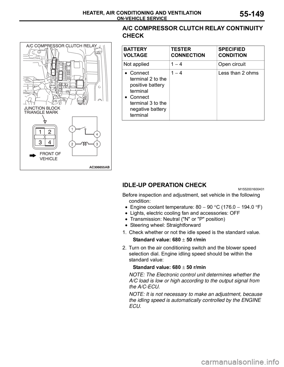
A/C COMPRESSOR CLUTCH RELAY CONTINUITY
CHECK
IDLE-UP OPERATION CHECK
M1552001600401
Before inspection and adjustment, set vehicle in the following
condition:
Engine coolant temperature: 80 90 C (176.0 194.0 F)
Lights, electric cooling fan and accessories: OFF
Transmission: Neutral ("N" or "P" position)
Steering wheel: Straightforward
1. Check whether or not the idle speed is the standard value.
Standard value: 680
50 r/min
2. Turn on the air conditioning switch and the blower speed
selection dial. Engine idling speed should be within the
standard value:
Standard value: 680
50 r/min
NOTE: The Electronic control unit determines whether the
A/C load is low or high according to the output signal from
the A/C-ECU.
NOTE: It is not necessary to make an adjustment, because
the idling speed is automatically controlled by the ENGINE
ECU. BATTERY
V O LTA G ETESTER
CONNECTIONSPECIFIED
CONDITION
Not applied 1
4 Open circuit
Connect
terminal 2 to the
positive battery
terminal
Connect
terminal 3 to the
negative battery
terminal1
4 Less than 2 ohms
Page 910 of 1500

HOW TO DIAGNOSE
GENERAL 00E-9
CABLES AND WIRES CHECKM1001005100041
1. Check connections for looseness, rust, and stains.
2. Check terminals and wires for corrosion.
3. Check terminals and wires for open circuit or impending
open circuit.
4. Check wire insulation and coating for damage, cracks, and
wear.
5. Check conductive parts of terminals for contact with other
metallic parts (vehicle body and other parts).
6. Check grounding parts to verify that there is complete
continuity between attaching bolt(s) and vehicle body.
7. Check for incorrect wiring.
8. Check that harnesses are secured to prevent contact with
sharp edges and corners or hot parts (exhaust manifold,
pipe, etc.).
9. Check that harnesses are secured firmly to provide enough
clearance from the fan pulley, fan belt, and other rotating or
moving parts.
10.Check that the harnesses between fixed parts (such as the
vehicle body) and vibrating parts (such as the engine) are
long enough to allow for vibration and movement.
BATTERY HANDLINGM1001005200048
Battery posts, terminals and related accessories con-
tain lead and lead compounds. WASH HANDS AFTER
HANDLING.
When checking or servicing does not require power from the
vehicle battery, be sure to disconnect the cable from the battery
(
) terminal. This will prevent problems that could be caused by
a short circuit. Disconnect the (
) battery terminal first and
reconnect it last.
GENERAL ELECTRICAL SYSTEM CHECKM1001005300045
A circuit consists of the power supply, switch, relay, load,
ground, etc. There are various methods to check a circuit
including an overall check, voltage check, short-circuit check,
and continuity check. Each of the methods briefly described
below applies only to circuits similar to the illustration.
Page 916 of 1500

14-1
GROUP 14
ENGINE COOLING
CONTENTS
GENERAL DESCRIPTION. . . . . . . . .14-2
SPECIAL TOOL . . . . . . . . . . . . . . . . .14-2
ENGINE COOLING DIAGNOSIS . . . .14-2
INTRODUCTION. . . . . . . . . . . . . . . . . . . . . 14-2
TROUBLESHOOTING STRATEGY . . . . . . 14-2
SYMPTOM CHART. . . . . . . . . . . . . . . . . . . 14-3
SYMPTOM PROCEDURES . . . . . . . . . . . . 14-3
ON-VEHICLE SERVICE . . . . . . . . . . .14-26
ENGINE COOLANT LEAK CHECK . . . . . . 14-26
RADIATOR CAP PRESSURE CHECK . . . . 14-27
ENGINE COOLANT REPLACEMENT . . . . 14-27
ENGINE COOLANT CONCENTRATION TEST14-29
FAN CONTROLLER CHECK . . . . . . . . . . . 14-29
FAN CONTROL RELAY CONTINUITY CHECK14-31
RADIATOR . . . . . . . . . . . . . . . . . . . . .14-32
REMOVAL AND INSTALLATION . . . . . . . . 14-32
THERMOSTAT . . . . . . . . . . . . . . . . . .14-35
REMOVAL AND INSTALLATION . . . . . . . . 14-35
INSPECTION. . . . . . . . . . . . . . . . . . . . . . . . 14-38
WATER PUMP . . . . . . . . . . . . . . . . . .14-39
REMOVAL AND INSTALLATION . . . . . . . . 14-39
WATER HOSE AND WATER PIPE . .14-40
REMOVAL AND INSTALLATION . . . . . . . . 14-40
INSPECTION. . . . . . . . . . . . . . . . . . . . . . . . 14-41
SPECIFICATIONS . . . . . . . . . . . . . . .14-42
FASTENER TIGHTENING
SPECIFICATIONS. . . . . . . . . . . . . . . . . . . . 14-42
SERVICE SPECIFICATION . . . . . . . . . . . . 14-43
CAPACITIES . . . . . . . . . . . . . . . . . . . . . . . . 14-43
SEALANTS . . . . . . . . . . . . . . . . . . . . . . . . . 14-43
Page 918 of 1500

ENGINE COOLING DIAGNOSIS
ENGINE COOLING14-3
SYMPTOM CHARTM1141005600393
SYMPTOM PROCEDURES
INSPECTION PROCEDURE 1: Coolant Leak
DIAGNOSIS
STEP 1. Check for coolant leaks.
When pressure testing the cooling system, slowly
release cooling system pressure to avoid being
burned by hot coolant.
Be sure to completely clean away any moisture from
the places checked.
When the tester is removed, be careful not to spill any
coolant.
When installing and removing the tester and when test-
ing, be careful not to deform the filler neck of the radia-
tor.
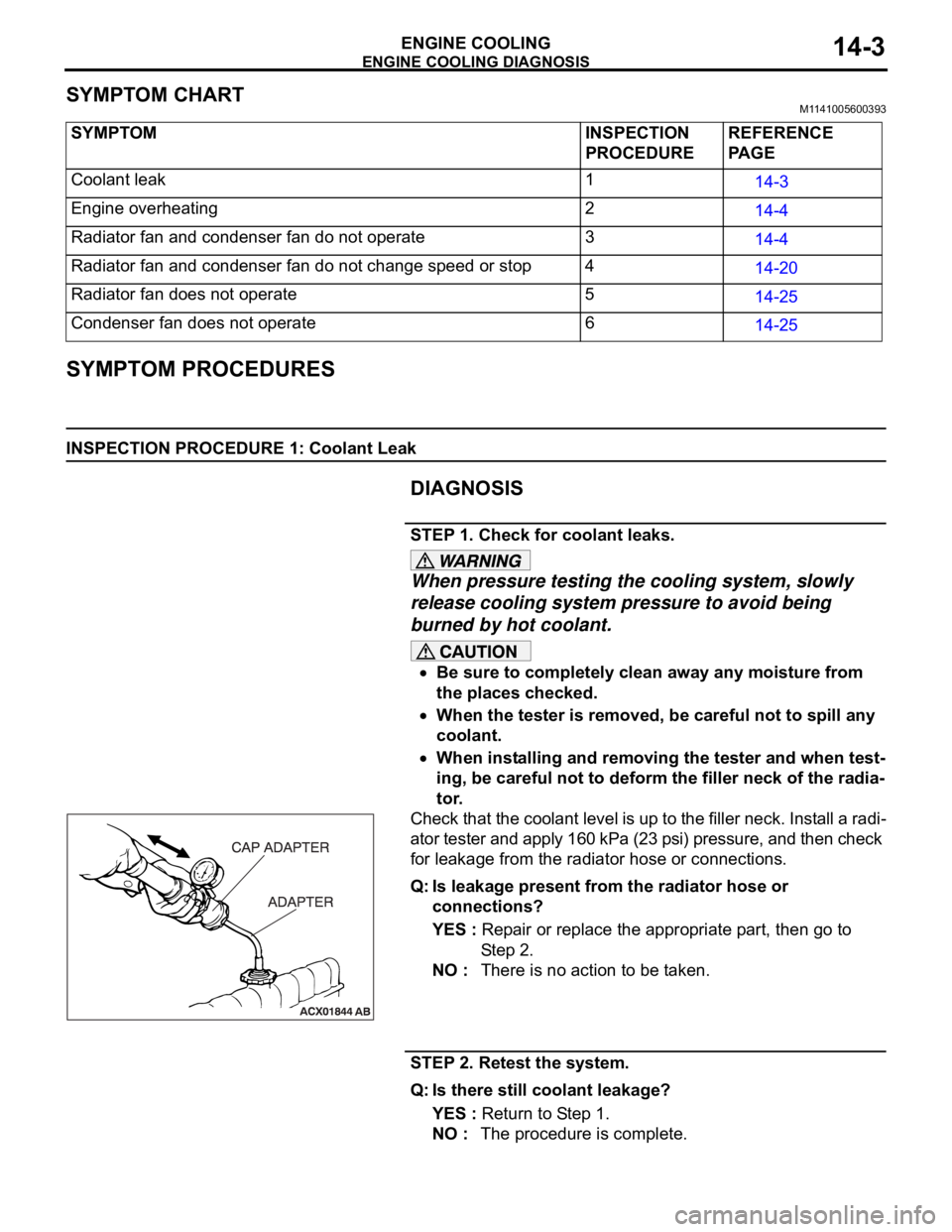
Check that the coolant level is up to the filler neck. Install a radi-
ator tester and apply 160 kPa (23 psi) pressure, and then check
for leakage from the radiator hose or connections.
Q: Is leakage present from the radiator hose or
connections?
YES : Repair or replace the appropriate part, then go to
St e p 2 .
NO : There is no action to be taken.
STEP 2. Retest the system.
Q: Is there still coolant leakage?
YES : Return to Step 1.
NO : The procedure is complete. SYMPTOM INSPECTION
PROCEDUREREFERENCE
PA G E
Coolant leak 1
14-3
Engine overheating 2
14-4
Radiator fan and condenser fan do not operate 3
14-4
Radiator fan and condenser fan do not change speed or stop 4
14-20
Radiator fan does not operate 5
14-25
Condenser fan does not operate 6
14-25