2005 MITSUBISHI 380 wheel torque
[x] Cancel search: wheel torquePage 1430 of 1500
DRIVE SHAFT ASSEMBLY
FRONT AXLE26-13
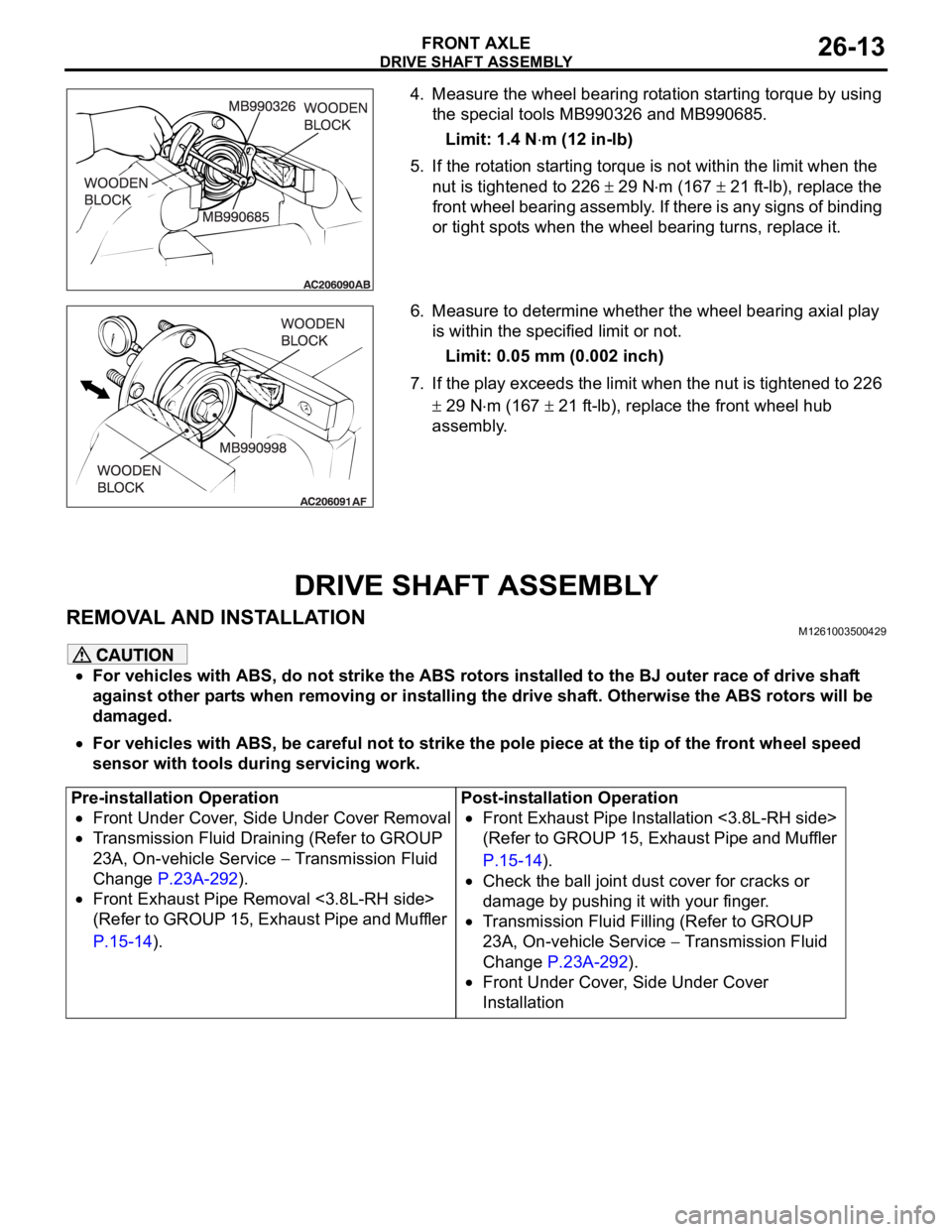
4. Measure the wheel bearing rotation starting torque by using
the special tools MB990326 and MB990685.
Limit: 1.4 N
m (12 in-lb)
5. If the rotation starting torque is not within the limit when the
nut is tightened to 226
29 Nm (167 21 ft-lb), replace the
front wheel bearing assembly. If there is any signs of binding
or tight spots when the wheel bearing turns, replace it.
6. Measure to determine whether the wheel bearing axial play
is within the specified limit or not.
Limit: 0.05 mm (0.002 inch)
7. If the play exceeds the limit when the nut is tightened to 226
29 Nm (167 21 ft-lb), replace the front wheel hub
assembly.
DRIVE SHAFT ASSEMBLY
REMOVAL AND INSTALLATIONM1261003500429
For vehicles with ABS, do not strike the ABS rotors installed to the BJ outer race of drive shaft
against other parts when removing or installing the drive shaft. Otherwise the ABS rotors will be
damaged.
For vehicles with ABS, be careful not to strike the pole piece at the tip of the front wheel speed
sensor with tools during servicing work.
Pre-installation Operation
Front Under Cover, Side Under Cover Removal
Transmission Fluid Draining (Refer to GROUP
23A, On-vehicle Service
Transmission Fluid
Change P.23A-292).
Front Exhaust Pipe Removal <3.8L-RH side>
(Refer to GROUP 15, Exhaust Pipe and Muffler
P.15-14).Post-installation Operation
Front Exhaust Pipe Installation <3.8L-RH side>
(Refer to GROUP 15, Exhaust Pipe and Muffler
P.15-14).
Check the ball joint dust cover for cracks or
damage by pushing it with your finger.
Transmission Fluid Filling (Refer to GROUP
23A, On-vehicle Service
Transmission Fluid
Change P.23A-292).
Front Under Cover, Side Under Cover
Installation
Page 1434 of 1500
DRIVE SHAFT ASSEMBLY
FRONT AXLE26-17
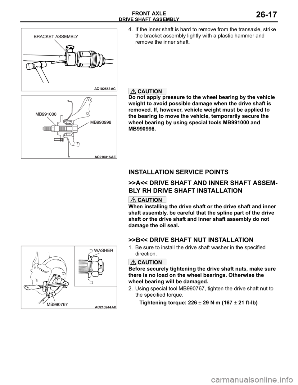
4. If the inner shaft is hard to remove from the transaxle, strike
the bracket assembly lightly with a plastic hammer and
remove the inner shaft.
Do not apply pressure to the wheel bearing by the vehicle
weight to avoid possible damage when the drive shaft is
removed. If, however, vehicle weight must be applied to
the bearing to move the vehicle, temporarily secure the
wheel bearing by using special tools MB991000 and
MB990998.
INSTALLATION SERVICE POINTS
.
>>A<< DRIVE SHAFT AND INNER SHAFT ASSEM-
BLY RH DRIVE SHAFT INSTALLATION
When installing the drive shaft or the drive shaft and inner
shaft assembly, be careful that the spline part of the drive
shaft or the drive shaft and inner shaft assembly do not
damage the oil seal.
.
>>B<< DRIVE SHAFT NUT INSTALLATION
1. Be sure to install the drive shaft washer in the specified
direction.
Before securely tightening the drive shaft nuts, make sure
there is no load on the wheel bearings. Otherwise the
wheel bearing will be damaged.
2. Using special tool MB990767, tighten the drive shaft nut to
the specified torque.
Tightening torque: 226
29 Nm (167 21 ft-lb)
Page 1446 of 1500
SPECIFICATIONS
FRONT AXLE26-29
SPECIFICATIONS
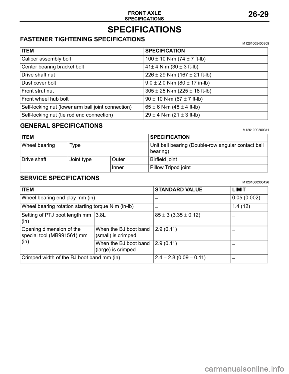
FASTENER TIGHTENING SPECIFICATIONSM1261005400309
GENERAL SPECIFICATIONSM1261000200311
SERVICE SPECIFICATIONSM1261000300426
ITEM SPECIFICATION
Caliper assembly bolt 100
10 Nm (74 7 ft-lb)
Center bearing bracket bolt 41
4 Nm (30 3 ft-lb)
Drive shaft nut 226
29 Nm (167 21 ft-lb)
Dust cover bolt 9.0
2.0 Nm (80 17 in-lb)
Front strut nut 305
25 Nm (225 18 ft-lb)
Front wheel hub bolt 90
10 Nm (67 7 ft-lb)
Self-locking nut (lower arm ball joint connection) 65
6 Nm (48 4 ft-lb)
Self-locking nut (tie rod end connection) 29
4 Nm (21 3 ft-lb)
ITEM SPECIFICATION
Wheel bearing Type Unit ball bearing (Double-row angular contact ball
bearing)
Drive shaft Joint type Outer Birfield joint
Inner Pillow Tripod joint
ITEM STANDARD VALUE LIMIT
Wheel bearing end play mm (in)
0.05 (0.002)
Wheel bearing rotation starting torque N
m (in-lb)1.4 (12)
Setting of PTJ boot length mm
(in)3.8L 85
3 (3.35 0.12)
Opening dimension of the
special tool (MB991561) mm
(in)When the BJ boot band
(small) is crimped2.9 (0.11)
When the BJ boot band
(large) is crimped2.9 (0.11)
Crimped width of the BJ boot band mm (in) 2.4 2.8 (0.09 0.11)
Page 1450 of 1500
REAR AXLE DIAGNOSIS
REAR AXLE27-3
SYMPTOM PROCEDURESM1271004400222
INSPECTION PROCEDURE 1: Abnormal Noise
DIAGNOSIS
STEP 1. Check the rear hub assembly installation bolts for
looseness.
Q: Are the rear hub assembly installation bolts loosened?
YES : Tighten the rear hub assembly installation bolts to the
specified torque 73
7 Nm (54 5 ft-lb). Then go to
St e p 4 .
NO : Go to Step 2.
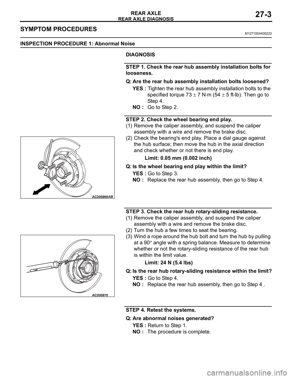
STEP 2. Check the wheel bearing end play.
(1) Remove the caliper assembly, and suspend the caliper
assembly with a wire and remove the brake disc.
(2) Check the bearing's end play. Place a dial gauge against
the hub surface; then move the hub in the axial direction
and check whether or not there is end play.
Limit: 0.05 mm (0.002 inch)
Q: Is the wheel bearing end play within the limit?
YES : Go to Step 3.
NO : Replace the rear hub assembly, then go to Step 4.
STEP 3. Check the rear hub rotary-sliding resistance.
(1) Remove the caliper assembly, and suspend the caliper
assembly with a wire and remove the brake disc.
(2) Turn the hub a few times to seat the bearing.
(3) Wind a rope around the hub bolt and turn the hub by pulling
at a 90
angle with a spring balance. Measure to determine
whether or not the rotary-sliding resistance of the rear hub
is within the limit value.
Limit: 24 N (5.4 lbs)
Q: Is the rear hub rotary-sliding resistance within the limit?
YES : Go to Step 4.
NO : Replace the rear hub assembly, then go to Step 4 .
STEP 4. Retest the systems.
Q: Are abnormal noises generated?
YES : Return to Step 1.
NO : The procedure is complete.
Page 1451 of 1500
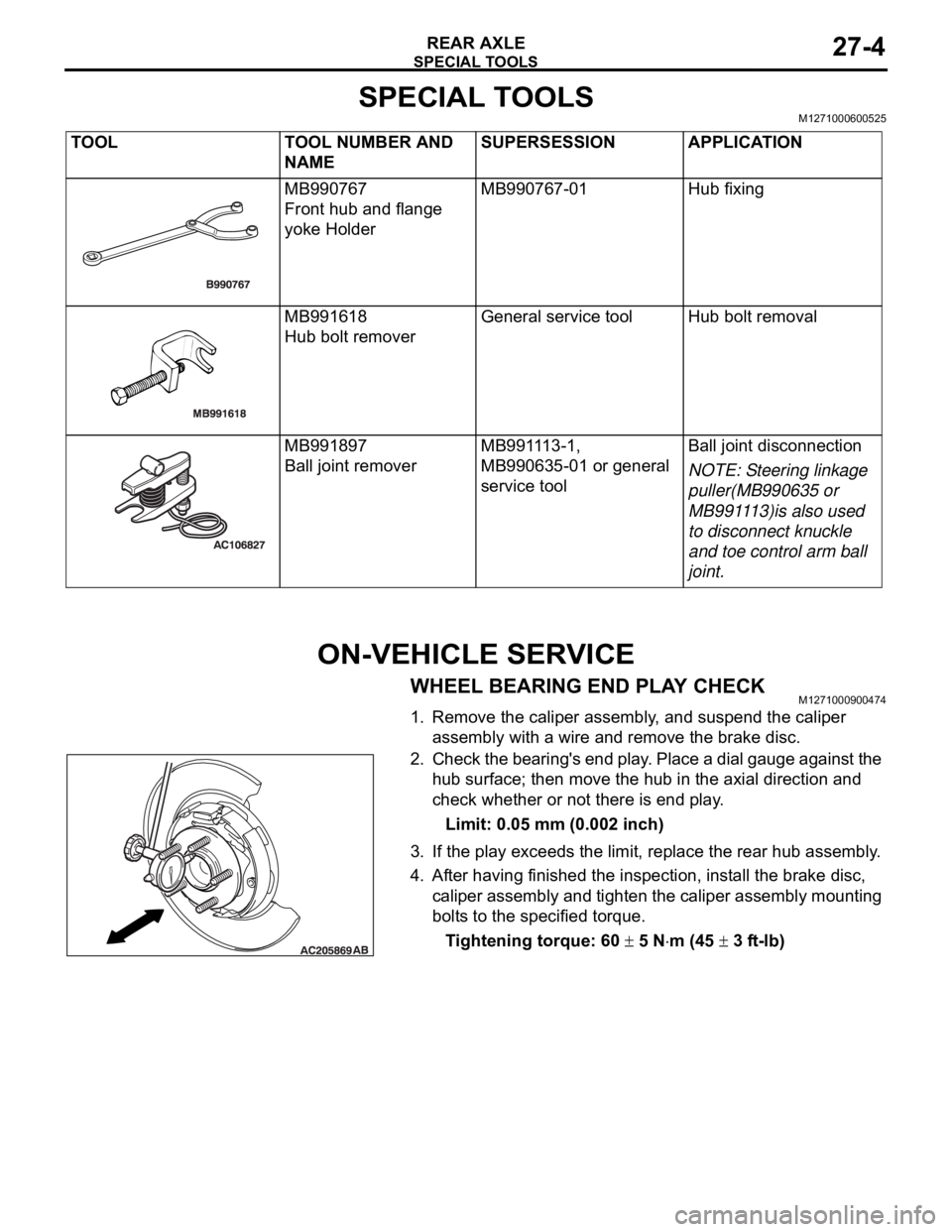
SPECIAL TOOLS
REAR AXLE27-4
SPECIAL TOOLSM1271000600525
ON-VEHICLE SERVICE
WHEEL BEARING END PLAY CHECKM1271000900474
1. Remove the caliper assembly, and suspend the caliper
assembly with a wire and remove the brake disc.
2. Check the bearing's end play. Place a dial gauge against the
hub surface; then move the hub in the axial direction and
check whether or not there is end play.
Limit: 0.05 mm (0.002 inch)
3. If the play exceeds the limit, replace the rear hub assembly.
4. After having finished the inspection, install the brake disc,
caliper assembly and tighten the caliper assembly mounting
bolts to the specified torque.
Tightening torque: 60
5 Nm (45 3 ft-lb) TOOL TOOL NUMBER AND
NAMESUPERSESSION APPLICATION
MB990767
Front hub and flange
yoke HolderMB990767-01 Hub fixing
MB991618
Hub bolt removerGeneral service tool Hub bolt removal
MB991897
Ball joint removerMB991113-1,
MB990635-01 or general
service toolBall joint disconnection
NOTE: Steering linkage
puller(MB990635 or
MB991113)is also used
to disconnect knuckle
and toe control arm ball
joint.
Page 1484 of 1500
AUTOMATIC TRANSMISSION DIAGNOSIS
AUTOMATIC TRANSMISSION23A-25
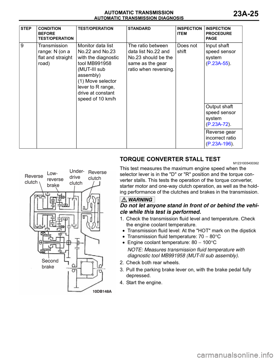
TORQUE CONVERTER STALL TESTM1231005400362
This test measures the maximum engine speed when the
selector lever is in the "D" or "R" position and the torque con-
verter stalls. This tests the operation of the torque converter,
starter motor and one-way clutch operation, as well as the hold-
ing performance of the clutches and brakes in the transmission.
Do not let anyone stand in front of or behind the vehi-
cle while this test is performed.
1. Check the transmission fluid level and temperature. Check
the engine coolant temperature.
Transmission fluid level: At the "HOT" mark on the dipstick
Transmission fluid temperature: 70 80C
Engine coolant temperature: 80 100C
NOTE: Measures transmission fluid temperature with
diagnostic tool MB991958 (MUT-III sub assembly).
2. Check both rear wheels.
3. Pull the parking brake lever on, with the brake pedal fully
depressed.
4. Start the engine. 9 Transmission
range: N (on a
flat and straight
road)Monitor data list
No.22 and No.23
with the diagnostic
tool MB991958
(MUT-III sub
assembly)
(1) Move selector
lever to R range,
drive at constant
speed of 10 km/hThe ratio between
data list No.22 and
No.23 should be the
same as the gear
ratio when reversing.Does not
shiftInput shaft
speed sensor
system
(P.23A-55).
Output shaft
speed sensor
system
(P.23A-72).
Reverse gear
incorrect ratio
(P.23A-196).
STEP CONDITION
BEFORE
TEST/OPERATIONTEST/OPERATION STANDARD INSPECTION
ITEMINSPECTION
PROCEDURE
PA G E
Page 1485 of 1500
AUTOMATIC TRANSMISSION DIAGNOSIS
AUTOMATIC TRANSMISSION23A-26
The throttle should not be fully open for any more than
five seconds.
If you repeat the stall test when the transmission fluid
temperature is greater than 80
C, move the selector
lever to the "N" position and let the engine run at
approximately 1,000 r/min for at least one minute. Wait
until the transmission fluid temperature returns to 80
C
or less.
5. Move the selector lever to the "D" position. Fully depress the
accelerator pedal and read the maximum engine speed at
this time.
Standard value: Stall speed: 2,100
2,600 r/min
6. Move the selector lever to the "R" position. Fully depress the
accelerator pedal and read the maximum engine speed.
Standard value: Stall speed: 2,100
2,600 r/min
TORQUE CONVERTER STALL TEST JUDGMENT
RESULTS
1. Stall speed is too high in both "D" and "R" range
Malfunction of the torque converter (Slippage on the splines
of the torque converter and the input shaft)
Low line pressure
Low-reverse brake slippage and malfunction of the one-way
clutch
2. Stall speed is too high in "D" range only
Underdrive clutch slippage
3. Stall speed is too high in "R" range only
Reverse clutch slippage
4. Stall speed is too low in both "D" and "R" ranges
Malfunction of the torque converter (Slippage of the
one-way clutch)
Insufficient engine output
HYDRAULIC PRESSURE TESTSM1231005500392
The transmission fluid temperature should be between 70
80C during the test.
1. Check the transmission fluid level and temperature. Check
engine coolant temperature.
Transmission fluid level: "HOT" mark on the dipstick
Transmission fluid temperature: 70 80C
Engine coolant temperature: 80 100C
2. Raise the vehicle so that the wheels are free to turn.