Page 1155 of 1500
SPECIFICATIONS
BODY42-88
COMPONENT IDENTIFICATIONSM1421005400246
APPLICABLE LOCATION IDENTIFICATION MARK
LH Front door P4FL
Rear door P4RL
RH Front door P4FR
Rear door P4RR
APPLICABLE SIDE IDENTIFICATION CLIP COLOR
LH Front door Pink
Rear door Yellow
RH Front door Turquoise
Rear door Blue
Page 1218 of 1500
PARKING BRAKE LINING AND DRUM
PARKING BRAKES36-11
>>C<< SHOE-TO-ANCHOR SPRING
INSTALLATION
The front and rear shoe-to-anchor springs are not inter-
changeable, so the blue spring must be installed at the
front side and the yellow spring must be installed at the
rear side.
Install the shoe-to-anchor springs in the order shown in the
illustration.
INSPECTIONM1361002600260
PARKING BRAKE LINING AND BRAKE DRUM
CHECK
1. Measure the thickness of the brake lining at several places.
Standard value: 2.8 mm (0.11 inch)
Minimum Limit: 1.0 mm (0.04 inch)
2. If the thickness of the brake lining is below the limit, replace
the shoe assemblies on both sides of the vehicle. Never
replace only one side.
3. Measure the inside diameter of the brake disc in two places
or more.
Standard value: 190.0 mm
Limit: 191.0 mm
4. If the inside diameter exceeds the limit, or if it is excessively
worn on one side, replace the brake disc.
Page 1244 of 1500

PRECAUTIONS BEFORE SERVICE
GENERAL00-23
HOW TO PERFORM VEHICLE IDENTIFICATION
NUMBER (VIN) WRITING
M1001011400063
The Vehicle Identification Number (VIN) is stored in the ECU by
the vehicle manufacture. If the VIN to be stored in the ECU is
eliminated fraudulently, the Malfunction Indicator Lamp (Check
Engine Lamp) illuminates and Diagnostic Trouble Code (DTC)
No.P0630 (VIN malfunction) is shown. When the ECU is
replaced, and entry of the VIN necessary due to DTC No.
P0630 (VIN malfunction). Enter the VIN in accordance with the
procedure as follows:
.
WRITING PROCEDURE
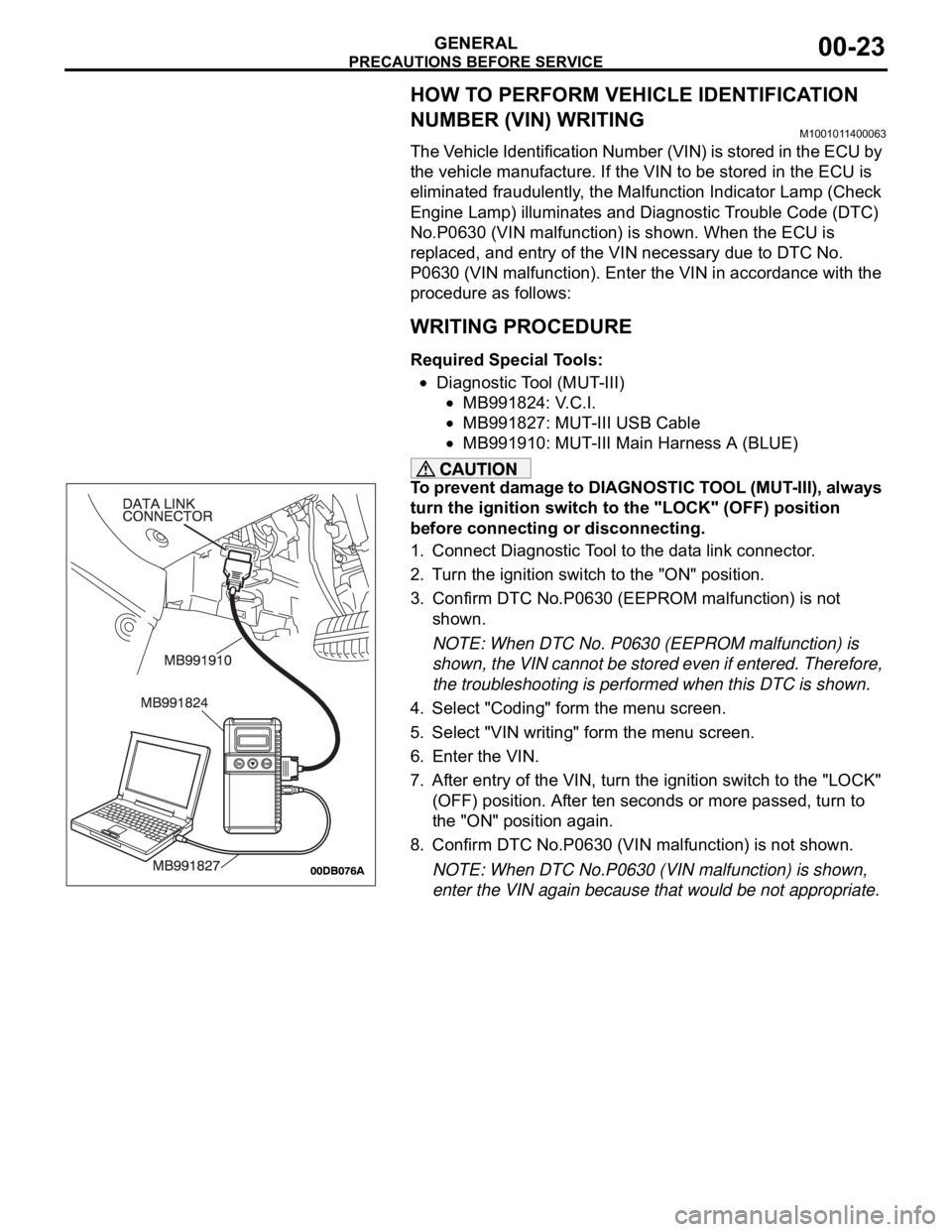
Required Special Tools:
Diagnostic Tool (MUT-III)
MB991824: V.C.I.
MB991827: MUT-III USB Cable
MB991910: MUT-III Main Harness A (BLUE)
To prevent damage to DIAGNOSTIC TOOL (MUT-III), always
turn the ignition switch to the "LOCK" (OFF) position
before connecting or disconnecting.
1. Connect Diagnostic Tool to the data link connector.
2. Turn the ignition switch to the "ON" position.
3. Confirm DTC No.P0630 (EEPROM malfunction) is not
shown.
NOTE: When DTC No. P0630 (EEPROM malfunction) is
shown, the VIN cannot be stored even if entered. Therefore,
the troubleshooting is performed when this DTC is shown.
4. Select "Coding" form the menu screen.
5. Select "VIN writing" form the menu screen.
6. Enter the VIN.
7. After entry of the VIN, turn the ignition switch to the "LOCK"
(OFF) position. After ten seconds or more passed, turn to
the "ON" position again.
8. Confirm DTC No.P0630 (VIN malfunction) is not shown.
NOTE: When DTC No.P0630 (VIN malfunction) is shown,
enter the VIN again because that would be not appropriate.
Page 1260 of 1500
MAINTENANCE SERVICE
GENERAL00-39
7. DRIVE BELTS (FOR ALTERNATOR, POWER
STEERING PUMP AND AIR CONDITIONING)
(CHECK)
M1001008700031
ALTERNATOR DRIVE BELT TENSION CHECK
<3.8L ENGINE>
.
WHEN USING DIAGNOSTIC TOOL (MUT-III)
Required Special Tools:
MB991668: Belt Tension Meter Set
Diagnostic Tool (MUT-III)
MB991824: Vehicle Communication Interface (V.C.I.)
MB991910: MUT-III Main Harness A (BLUE)
To prevent damage to DIAGNOSTIC TOOL (MUT-III), always
turn the ignition switch to the "LOCK" (OFF) position
before connecting or disconnecting.
1. Connect Belt Tension Meter Set (MB991668) to V.C.I
(MB991824).
2. Connect MUT-III Main Harness A (BLUE) (MB991910) to
V.C.I (MB991824).
3. Connect MUT-III Main Harness A (BLUE) (MB991910) to the
data link connector.
4. Turn the ignition switch to the "ON" position and select "Belt
Tension" from the menu V.C.I (MB991824) screen.
Page 1263 of 1500

MAINTENANCE SERVICE
GENERAL00-42
ALTERNATOR DRIVE BELT TENSION
ADJUSTMENT
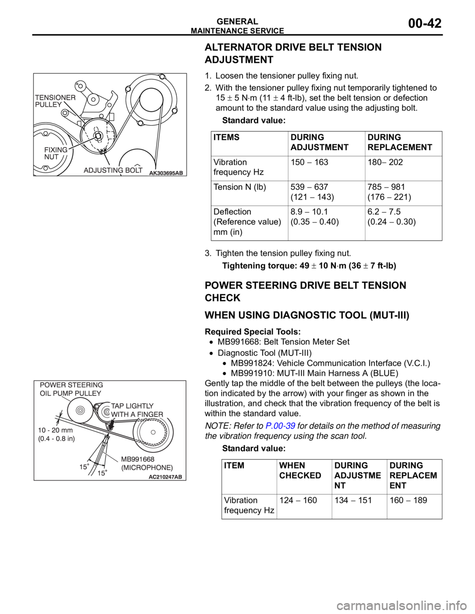
.1. Loosen the tensioner pulley fixing nut.
2. With the tensioner pulley fixing nut temporarily tightened to
15
5 Nm (11 4 ft-lb), set the belt tension or defection
amount to the standard value using the adjusting bolt.
Standard value:
3. Tighten the tension pulley fixing nut.
Tightening torque: 49
10 Nm (36 7 ft-lb)
POWER STEERING DRIVE BELT TENSION
CHECK
.
WHEN USING DIAGNOSTIC TOOL (MUT-III)
Required Special Tools:
MB991668: Belt Tension Meter Set
Diagnostic Tool (MUT-III)
MB991824: Vehicle Communication Interface (V.C.I.)
MB991910: MUT-III Main Harness A (BLUE)
Gently tap the middle of the belt between the pulleys (the loca-
tion indicated by the arrow) with your finger as shown in the
illustration, and check that the vibration frequency of the belt is
within the standard value.
NOTE: Refer to P.00-39 for details on the method of measuring
the vibration frequency using the scan tool.
Standard value:
.
ITEMS DURING
ADJUSTMENTDURING
REPLACEMENT
Vibration
frequency Hz150
163 180 202
Tension N (lb) 539
637
(121
143)785
981
(176
221)
Deflection
(Reference value)
mm (in)8.9
10.1
(0.35
0.40)6.2
7.5
(0.24
0.30)
ITEM WHEN
CHECKEDDURING
ADJUSTME
NTDURING
REPLACEM
ENT
Vibration
frequency Hz124
160 134 151 160 189