2005 MITSUBISHI 380 Shift
[x] Cancel search: ShiftPage 1462 of 1500

GENERAL DESCRIPTION
AUTOMATIC TRANSMISSION23A-3
GENERAL DESCRIPTIONM1231000100366
ITEM SPECIFICATION
Transmission modelF5A5A-4-C5Z
Engine model 6G75-S4-MP
Torque converter Type 3-element, 1-stage, 2-phase type
Lock-up Provided
Stall torque ratio 1.71
Transmission type5 forward speeds, 1 reverse speed, fully automatic
Transmission gear
ratio1st 3.789
2nd 2.162
3rd 1.421
4th 1.000
5th 0.686
Reverse 3.117
Final reduction ratio (Differential gear ratio) 3.325
Clutch Multi-disc type 4 sets
Brake Multi-disc type 2 sets, band type 1 set
Manual control system P-R-N-D (4 position) + Sport mode (up, down)
Shift pattern control Electronic control
Hydraulic control during shifting Electronic control (Each clutch hydraulically independently
controlled)
Torque converter clutch control Electronic control
Transmission fluid Specified lubricants MITSUBISHI ELC4-SP III
Quantity (litres) 8.4
Page 1466 of 1500
GENERAL DESCRIPTION
AUTOMATIC TRANSMISSION23A-7
ELECTRONICALLY-CONTROLLED SYSTEM
.
INVECS-II
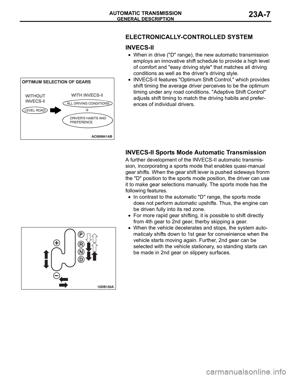
When in drive ("D" range), the new automatic transmission
employs an innovative shift schedule to provide a high level
of comfort and "easy driving style" that matches all driving
conditions as well as the driver's driving style.
INVECS-II features "Optimum Shift Control," which provides
shift timing the average driver perceives to be the optimum
timing under any road conditions. "Adaptive Shift Control"
adjusts shift timing to match the driving habits and prefer-
ences of individual drivers.
.
INVECS-II Sports Mode Automatic Transmission
A further development of the INVECS-II automatic transmis-
sion, incorporating a sports mode that enables quasi-manual
gear shifts. When the gear shift lever is pushed sideways fronm
the "D" position to the sports mode position, the driver can use
it to make gear selections manually. The sports mode has the
following features.
In contrast to the automatic "D" range, the sports mode
does not perform automatic upshifts. Thus, the engine can
be driven fully into its red zone.
For more rapid gear shifting, it is possible to shift directly
from 4th gear to 2nd gear, therby skipping a gear.
When the vehicle decelerates and stops, the system auto-
maticaly shifts down to 1st gear for conveinience when the
vehicle starts moving again. Further, 2nd gear can be
selected with the vehicle stationary, so standing starts can
be made in 2nd gear on slippery surfaces.
.
Page 1467 of 1500
GENERAL DESCRIPTION
AUTOMATIC TRANSMISSION23A-8
FEATURES
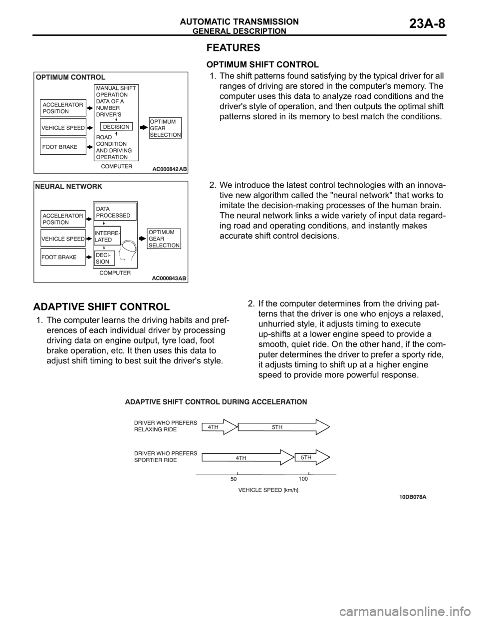
OPTIMUM SHIFT CONTROL
1. The shift patterns found satisfying by the typical driver for all
ranges of driving are stored in the computer's memory. The
computer uses this data to analyze road conditions and the
driver's style of operation, and then outputs the optimal shift
patterns stored in its memory to best match the conditions.
2. We introduce the latest control technologies with an innova-
tive new algorithm called the "neural network" that works to
imitate the decision-making processes of the human brain.
The neural network links a wide variety of input data regard-
ing road and operating conditions, and instantly makes
accurate shift control decisions.
.
ADAPTIVE SHIFT CONTROL
1. The computer learns the driving habits and pref-
erences of each individual driver by processing
driving data on engine output, tyre load, foot
brake operation, etc. It then uses this data to
adjust shift timing to best suit the driver's style.2. If the computer determines from the driving pat-
terns that the driver is one who enjoys a relaxed,
unhurried style, it adjusts timing to execute
up-shifts at a lower engine speed to provide a
smooth, quiet ride. On the other hand, if the com-
puter determines the driver to prefer a sporty ride,
it adjusts timing to shift up at a higher engine
speed to provide more powerful response.
.
Page 1469 of 1500
GENERAL DESCRIPTION
AUTOMATIC TRANSMISSION23A-10
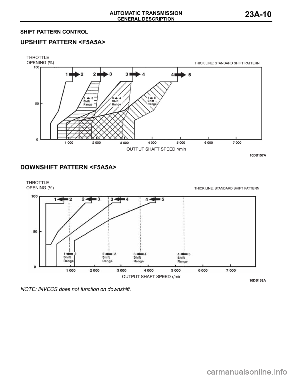
SHIFT PATTERN CONTROL.
UPSHIFT PATTERN
.
DOWNSHIFT PATTERN
NOTE: INVECS does not function on downshift.
Page 1476 of 1500
AUTOMATIC TRANSMISSION DIAGNOSIS
AUTOMATIC TRANSMISSION23A-17
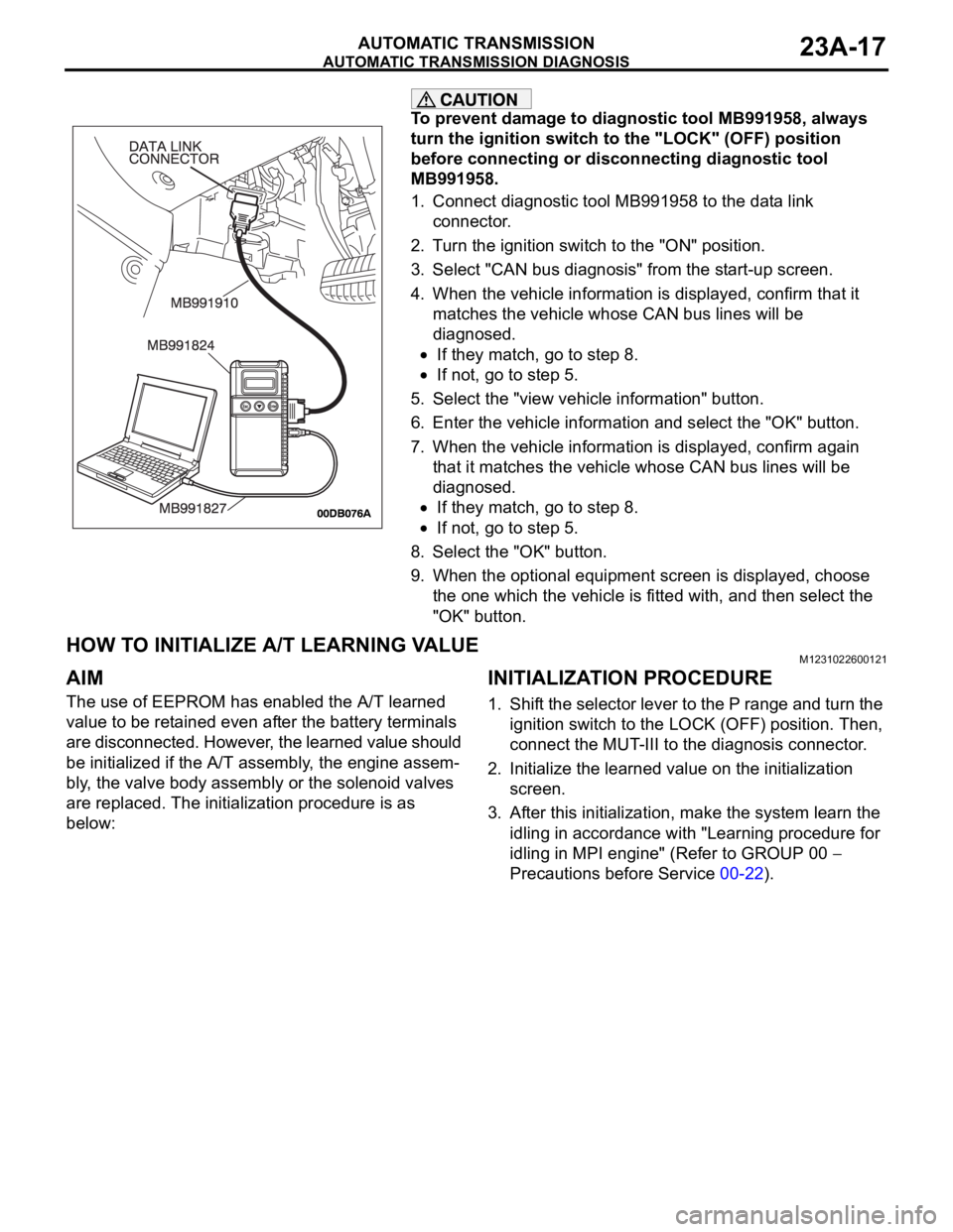
To prevent damage to diagnostic tool MB991958, always
turn the ignition switch to the "LOCK" (OFF) position
before connecting or disconnecting diagnostic tool
MB991958.
1. Connect diagnostic tool MB991958 to the data link
connector.
2. Turn the ignition switch to the "ON" position.
3. Select "CAN bus diagnosis" from the start-up screen.
4. When the vehicle information is displayed, confirm that it
matches the vehicle whose CAN bus lines will be
diagnosed.
If they match, go to step 8.
If not, go to step 5.
5. Select the "view vehicle information" button.
6. Enter the vehicle information and select the "OK" button.
7. When the vehicle information is displayed, confirm again
that it matches the vehicle whose CAN bus lines will be
diagnosed.
If they match, go to step 8.
If not, go to step 5.
8. Select the "OK" button.
9. When the optional equipment screen is displayed, choose
the one which the vehicle is fitted with, and then select the
"OK" button.
HOW TO INITIALIZE A/T LEARNING VALUEM1231022600121
AIM
The use of EEPROM has enabled the A/T learned
value to be retained even after the battery terminals
are disconnected. However, the learned value should
be initialized if the A/T assembly, the engine assem-
bly, the valve body assembly or the solenoid valves
are replaced. The initialization procedure is as
below:
INITIALIZATION PROCEDURE
1. Shift the selector lever to the P range and turn the
ignition switch to the LOCK (OFF) position. Then,
connect the MUT-III to the diagnosis connector.
2. Initialize the learned value on the initialization
screen.
3. After this initialization, make the system learn the
idling in accordance with "Learning procedure for
idling in MPI engine" (Refer to GROUP 00
Precautions before Service 00-22).
Page 1477 of 1500

AUTOMATIC TRANSMISSION DIAGNOSIS
AUTOMATIC TRANSMISSION23A-18
FAIL-SAFE/BACKUP FUNCTIONM1231008300234
When a malfunction of a main sensor or actuator is
detected by the A/T-ECU, the transmission is con-
trolled by pre-set control logic to maintain safe condi-
tions for driving.The following table shows how the fail-safe/backup
function affects vehicle driveability and operation.
MALFUNCTIONING ITEM JUDGEMENT
CONDITIONCONTROL DEFAULT DURING MALFUNCTION
Input shaft speed sensor If no output pulse
from the input shaft
speed sensor is
detected for one
second or more
when the vehicle
speed is 30 km/h (19
mph) or greater.The diagnostic trouble code is recorded when the
malfunction occurs during 4 monitoring periods in
one drive cycle. When the judgment condition is
met, the transmission holds 3rd gear or 2nd gear,
depending on speed, as a fail-safe.
Output shaft speed sensor The output signal
from the output shaft
speed sensor is not
present for one
second or more
while the vehicle is
driven.The diagnostic trouble code is recorded when the
malfunction occurs during 4 monitoring periods in
one drive cycle. When the judgment condition is
met, the transmission holds 3rd gear or 2nd gear,
depending on speed, as a fail-safe.
Low-reverse solenoid valve Solenoid valve
resistance is below
2.7 ohms for 0.32
seconds.The diagnostic trouble code is recorded when the
malfunction occurs during 5 monitoring periods in
one drive cycle. When the judgment condition is
met, the A/T control relay is turned off. The
transmission will only operate in 3rd and reverse
gears until the system is repaired. Underdrive solenoid valve
Second solenoid valve
Overdrive solenoid valve
Reduction (RED) solenoid valve
Damper control clutch (DCC)
solenoid valve
Incomplete shifting 1st The gear ratio value
from the output shaft
speed sensor is not
the same as the
output from the input
shaft speed sensor
for one second after
shifting has been
completed.The diagnostic trouble code is recorded when the
malfunction occurs during 5 monitoring periods in
one drive cycle. When the judgment condition is
met, the A/T control relay is turned off. The
transmission will only operate in 3rd and reverse
gears until the system is repaired. 2nd
3rd
4th
5th
Reverse
A/T control relay A/T control relay
voltage is less than
seven volts for 0.1
second after the
ignition switch is
turned "ON."The A/T control relay is switched off. The
transmission will only operate in 3rd and reverse
gears until the system is repaired.
Malfunction in the A/T-ECU Malfunction has
occurred in the
A/T-ECU.The A/T control relay is switched off. The
transmission will only operate in 3rd and reverse
gears until the system is repaired.
Page 1478 of 1500
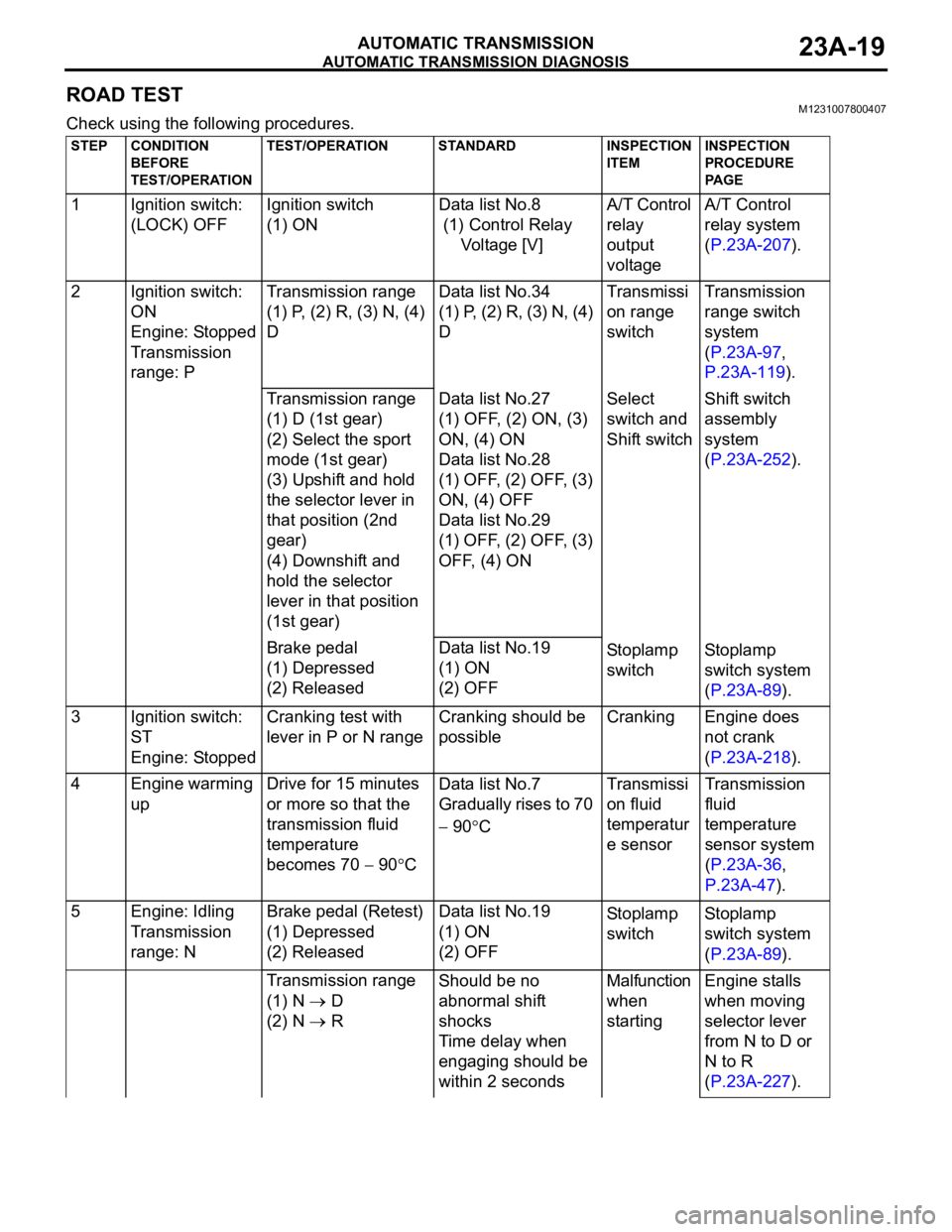
AUTOMATIC TRANSMISSION DIAGNOSIS
AUTOMATIC TRANSMISSION23A-19
ROAD TESTM1231007800407
Check using the following procedures.
STEP CONDITION
BEFORE
TEST/OPERATIONTEST/OPERATION STANDARD INSPECTION
ITEMINSPECTION
PROCEDURE
PA G E
1 Ignition switch:
(LOCK) OFFIgnition switch
(1) ONData list No.8
(1) Control Relay
Voltage [V]A/T Control
relay
output
voltageA/T Control
relay system
(P.23A-207).
2 Ignition switch:
ON
Engine: Stopped
Transmission
range: PTransmission range
(1) P, (2) R, (3) N, (4)
DData list No.34
(1) P, (2) R, (3) N, (4)
DTransmissi
on range
switchTransmission
range switch
system
(P.23A-97,
P.23A-119).
Transmission range
(1) D (1st gear)
(2) Select the sport
mode (1st gear)
(3) Upshift and hold
the selector lever in
that position (2nd
gear)
(4) Downshift and
hold the selector
lever in that position
(1st gear)Data list No.27
(1) OFF, (2) ON, (3)
ON, (4) ON
Data list No.28
(1) OFF, (2) OFF, (3)
ON, (4) OFF
Data list No.29
(1) OFF, (2) OFF, (3)
OFF, (4) ONSelect
switch and
Shift switchShift switch
assembly
system
(P.23A-252).
Brake pedal
(1) Depressed
(2) ReleasedData list No.19
(1) ON
(2) OFFSto pl amp
switchSt o pla mp
switch system
(P.23A-89).
3 Ignition switch:
ST
Engine: StoppedCranking test with
lever in P or N rangeCranking should be
possibleCranking Engine does
not crank
(P.23A-218).
4 Engine warming
upDrive for 15 minutes
or more so that the
transmission fluid
temperature
becomes 70
90CData list No.7
Gradually rises to 70
90CTransmissi
on fluid
temperatur
e sensorTransmission
fluid
temperature
sensor system
(P.23A-36,
P.23A-47).
5 Engine: Idling
Transmission
range: NBrake pedal (Retest)
(1) Depressed
(2) ReleasedData list No.19
(1) ON
(2) OFFSto pl amp
switchSt o pla mp
switch system
(P.23A-89).
Transmission range
(1) N
D
(2) N
RShould be no
abnormal shift
shocks
Time delay when
engaging should be
within 2 secondsMalfunction
when
startingEngine stalls
when moving
selector lever
from N to D or
N to R
(P.23A-227).
Page 1479 of 1500

AUTOMATIC TRANSMISSION DIAGNOSIS
AUTOMATIC TRANSMISSION23A-20
Shift shock
when shifting
from N to D and
long delay
(P.23A-229).
Shift shock
when shifting
from N to R and
long delay
(P.23A-232).
Shift shock
when shifting
from N to D, N
to R and long
delay
(P.23A-235).
Does not
moveDoes not move
forward
(P.23A-220).
Does not move
in reverse
(P.23A-223).
Does not move
(forward or in
reverse)
(P.23A-226).
6 Transmission
range: N (on a
flat and straight
road)Gear range and
vehicle speed (Each
condition should be
maintained for 10
seconds or more).
(1) Idling in 1st gear
(Vehicle stopped)
(2) Driving at
constant speed of 10
km/h in 1st gear
(3) Driving at
constant speed of 30
km/h in 2nd gear
(4) Driving at
constant speed of 50
km/h in 3rd gear
(5) Driving at
constant speed of 70
km/h in 4th gear
(6) Driving at
constant speed of 70
km/h in 5th gearData list No.11
(2) 1st, (3) 2nd, (4)
3rd, (5) 4th, (6) 5thShift
position-
STEP CONDITION
BEFORE
TEST/OPERATIONTEST/OPERATION STANDARD INSPECTION
ITEMINSPECTION
PROCEDURE
PA G E