2005 MITSUBISHI 380 ECO mode
[x] Cancel search: ECO modePage 1243 of 1500

PRECAUTIONS BEFORE SERVICE
GENERAL00-22
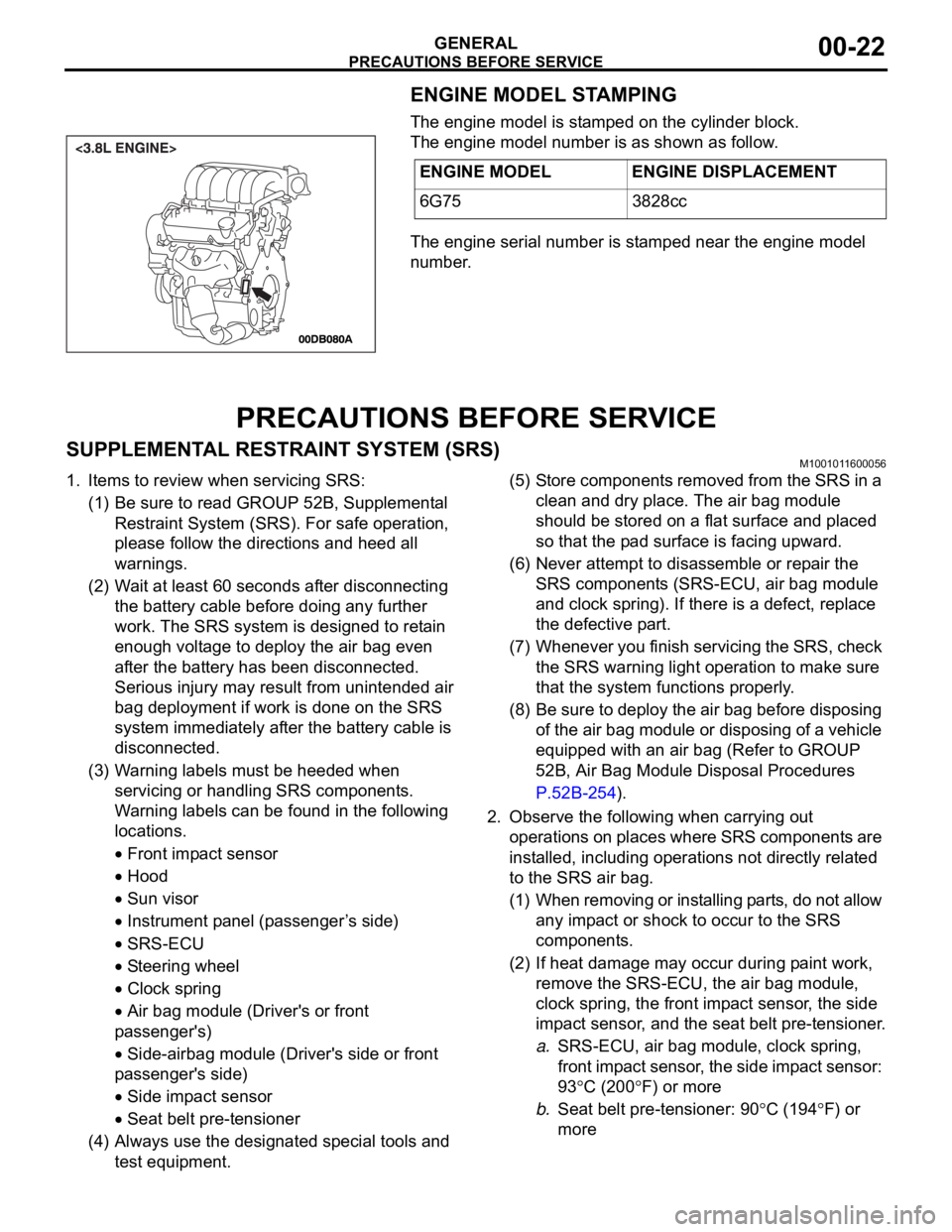
ENGINE MODEL STAMPING
The engine model is stamped on the cylinder block.
The engine model number is as shown as follow.
The engine serial number is stamped near the engine model
number.
PRECAUTIONS BEFORE SERVICE
SUPPLEMENTAL RESTRAINT SYSTEM (SRS)M1001011600056
1. Items to review when servicing SRS:
(1) Be sure to read GROUP 52B, Supplemental
Restraint System (SRS). For safe operation,
please follow the directions and heed all
warnings.
(2) Wait at least 60 seconds after disconnecting
the battery cable before doing any further
work. The SRS system is designed to retain
enough voltage to deploy the air bag even
after the battery has been disconnected.
Serious injury may result from unintended air
bag deployment if work is done on the SRS
system immediately after the battery cable is
disconnected.
(3) Warning labels must be heeded when
servicing or handling SRS components.
Warning labels can be found in the following
locations.
Front impact sensor
Hood
Sun visor
Instrument panel (passenger ’s side)
SRS-ECU
Steering wheel
Clock spring
Air bag module (Driver's or front
passenger's)
Side-airbag module (Driver's side or front
passenger's side)
Side impact sensor
Seat belt pre-tensioner
(4) Always use the designated special tools and
test equipment.(5) Store components removed from the SRS in a
clean and dry place. The air bag module
should be stored on a flat surface and placed
so that the pad surface is facing upward.
(6) Never attempt to disassemble or repair the
SRS components (SRS-ECU, air bag module
and clock spring). If there is a defect, replace
the defective part.
(7) Whenever you finish servicing the SRS, check
the SRS warning light operation to make sure
that the system functions properly.
(8) Be sure to deploy the air bag before disposing
of the air bag module or disposing of a vehicle
equipped with an air bag (Refer to GROUP
52B, Air Bag Module Disposal Procedures
P.52B-254).
2. Observe the following when carrying out
operations on places where SRS components are
installed, including operations not directly related
to the SRS air bag.
(1) When removing or installing parts, do not allow
any impact or shock to occur to the SRS
components.
(2) If heat damage may occur during paint work,
remove the SRS-ECU, the air bag module,
clock spring, the front impact sensor, the side
impact sensor, and the seat belt pre-tensioner.
a.SRS-ECU, air bag module, clock spring,
front impact sensor, the side impact sensor:
93
C (200F) or more
b.Seat belt pre-tensioner: 90
C (194F) or
more ENGINE MODEL ENGINE DISPLACEMENT
6G75 3828cc
Page 1255 of 1500

LUBRICATION AND MAINTENANCE
GENERAL00-34
LUBRICATION AND MAINTENANCEM1001001200336
Maintenance and lubrication service recommenda-
tions have been compiled to provide maximum pro-
tection for the vehicle owner's investment against all
reasonable types of driving conditions. Since these
conditions vary with the individual vehicle owner's
driving habits, the area in which the vehicle is oper-
ated and the type of driving to which the vehicle is
subjected, it is necessary to prescribe lubrication and
maintenance service on a time frequency as well as
mileage interval basis.
Oils, lubricants and greases are classified and
graded according to standards recommended by the
Society of Automotive Engineers (SAE) and the Aus-
tralian Petroleum Institute (API).
MAINTENANCE SCHEDULES
For Information on service maintenance refer to the
"Service handbook".
ENGINE OIL
Tests have shown that laboratory animals
develop skin cancer after prolonged contact with
used engine oil. Accordingly, the potential exists
for humans to develop a number of skin disor-
ders, including cancer, from such exposure to
used engine oil. Therefore, when changing
engine oil, be careful not to touch it as much as
possible. Protective clothing and gloves, that
cannot be penetrated by oil, should be worn. The
skin should be thoroughly washed with soap and
water, or use waterless hand cleaner, to remove
any used engine oil. Do not use petrol, thinners,
or solvents.Either of the following engine oils should be used:
1. Engine oil conforming to the ACEA classification:
"For service A1, A2 or A3.
2. Engine oil conforming to the API classification:
"For service SG" or higher.
FUEL USAGE STATEMENT
Using leaded petrol in this car will damage the
catalytic converters and heated oxygen sensors,
and affect the warranty coverage validity.
This vehicle must use unleaded petrol only.
This vehicle has a fuel filler tube which is especially
designed to accept only the smaller-diameter
unleaded petrol dispensing nozzle.
The 3.8L model is designed to operate on unleaded
petrol having an octane rating (DIN 51607) of 90
RON or higher.
.
PETROL CONTAINING ALCOHOL
Some petrol sold at service stations contain alcohol
although they may not be so identified.
Using fuels containing alcohol is not recommended
unless the nature of the blend can be determined as
being satisfactory, as follows.
Gasohol: A mixture of 10% ethanol and 90%
unleaded gasoline may be used in your vehicle. If
driveability problems are experienced as a result of
using gasohol, it is recommended that the vehicle be
operated on petrol.
Methanol: Do not use petrol containing methanol
(wood alcohol). Using this type of alcohol can result
in vehicle performance deterioration and damage
critical parts in the fuel system components. Fuel
system damage and performance problems resulting
from the use of petrol containing methanol may not
be covered by the new vehicle warranty.
MATERIALS ADDED TO FUEL
Indiscriminate use of fuel system cleaning agents
should be avoided. Many materials intended for gum
and varnish removal may contain highly active sol-
vents or similar ingredients that can be harmful to
gasket and diaphragm materials used in fuel system
component parts.
Page 1316 of 1500

TRACTION CONTROL SYSTEM (TCL) DIAGNOSIS
TRACTION CONTROL SYSTEM (TCL)13C-37
ACTUATOR TEST REFERENCE TABLEM1136003600067
NOTE: If the ABS-8 ECU or the active wheel
speed sensor are disconnected, or if the wiring is
an open/ short circuit, the ABS 8 ECU will shut
off power supply to the respective wheel speed
sensor. All other wheel speed sensors will oper-
ate normally. To restore the power supply, the
ignition switch must be turned to the "OFF" posi-
tion then to the "ON" position again.The diagnostic tool activates the following actuators
for testing. (Refer to P.13C-3).
NOTE: Since the TCL is controlled with the same ABS/TCL-ECU used to control the ABS, the FL, FR, RL or
RR Wheel ABS Drive testing items (No.01 to 04) used only for the ABS also appear. MUT-III
DIAGNOSTIC TOOL
DISPLAYITEM NO. CHECK ITEM PARTS TO BE ACTIVATED
FL wheel ABS Drive* 01 Solenoid valve for front left wheel Solenoid valves and pump
motors in the hydraulic unit
(simple inspection mode) FR wheel ABS Drive* 02 Solenoid valve for front right wheel
RL wheel ABS Drive* 03 Solenoid valve for rear left wheel
RR wheel ABS
Drive*04 Solenoid valve for rear right wheel
Engine TCL Drive 09 TCL operation check Outputs the engine torque
control signal (engine torque =
0) to PCM for three seconds.
Page 1464 of 1500

GENERAL DESCRIPTION
AUTOMATIC TRANSMISSION23A-5
FUNCTION ELEMENT TABLE
: Function element : Not applicable
NOTE: * operates only when the vehicle is stationary [at approximately 10 km/h (6.2 mph) or less].
OPERATING
ELEMENTSTART PARKING
MECHANI
SMUNDER
DRIVE
CLUTCH
(UD)REVERSE
CLUTCH
(REV)OVER-
DRIVE
CLUTCH
(OD)DIRECT
CLUTCH
(DIR)LOW-
REVERSE
BRAKE
(LR)SECOND
BRAKE
(2ND)REDUCTI-
ON
BRAKE
(RB) TRANSMISSION
RANGE
POK
R
NOK
Sport
mode1st*
2nd
3rd
4th
5th
Page 1478 of 1500

AUTOMATIC TRANSMISSION DIAGNOSIS
AUTOMATIC TRANSMISSION23A-19
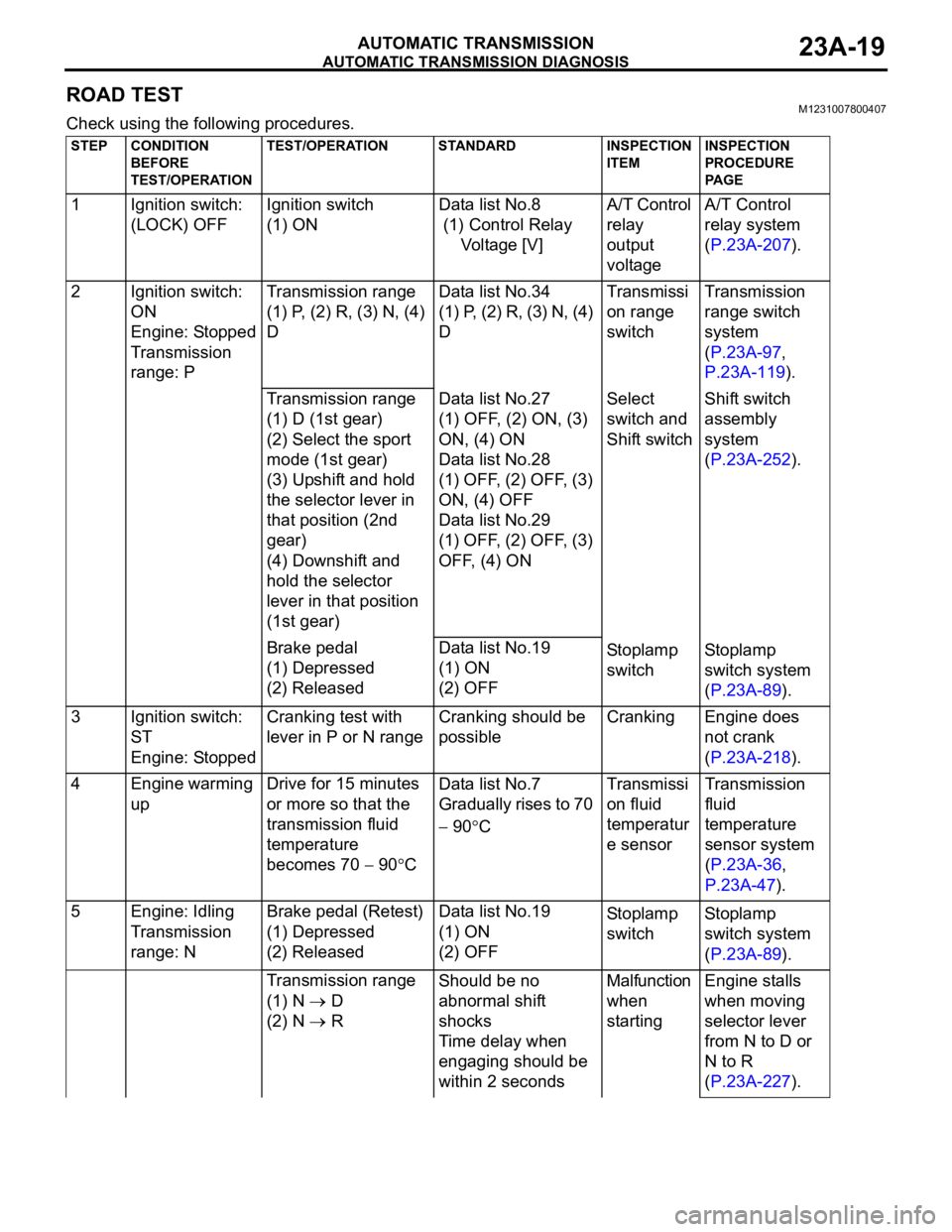
ROAD TESTM1231007800407
Check using the following procedures.
STEP CONDITION
BEFORE
TEST/OPERATIONTEST/OPERATION STANDARD INSPECTION
ITEMINSPECTION
PROCEDURE
PA G E
1 Ignition switch:
(LOCK) OFFIgnition switch
(1) ONData list No.8
(1) Control Relay
Voltage [V]A/T Control
relay
output
voltageA/T Control
relay system
(P.23A-207).
2 Ignition switch:
ON
Engine: Stopped
Transmission
range: PTransmission range
(1) P, (2) R, (3) N, (4)
DData list No.34
(1) P, (2) R, (3) N, (4)
DTransmissi
on range
switchTransmission
range switch
system
(P.23A-97,
P.23A-119).
Transmission range
(1) D (1st gear)
(2) Select the sport
mode (1st gear)
(3) Upshift and hold
the selector lever in
that position (2nd
gear)
(4) Downshift and
hold the selector
lever in that position
(1st gear)Data list No.27
(1) OFF, (2) ON, (3)
ON, (4) ON
Data list No.28
(1) OFF, (2) OFF, (3)
ON, (4) OFF
Data list No.29
(1) OFF, (2) OFF, (3)
OFF, (4) ONSelect
switch and
Shift switchShift switch
assembly
system
(P.23A-252).
Brake pedal
(1) Depressed
(2) ReleasedData list No.19
(1) ON
(2) OFFSto pl amp
switchSt o pla mp
switch system
(P.23A-89).
3 Ignition switch:
ST
Engine: StoppedCranking test with
lever in P or N rangeCranking should be
possibleCranking Engine does
not crank
(P.23A-218).
4 Engine warming
upDrive for 15 minutes
or more so that the
transmission fluid
temperature
becomes 70
90CData list No.7
Gradually rises to 70
90CTransmissi
on fluid
temperatur
e sensorTransmission
fluid
temperature
sensor system
(P.23A-36,
P.23A-47).
5 Engine: Idling
Transmission
range: NBrake pedal (Retest)
(1) Depressed
(2) ReleasedData list No.19
(1) ON
(2) OFFSto pl amp
switchSt o pla mp
switch system
(P.23A-89).
Transmission range
(1) N
D
(2) N
RShould be no
abnormal shift
shocks
Time delay when
engaging should be
within 2 secondsMalfunction
when
startingEngine stalls
when moving
selector lever
from N to D or
N to R
(P.23A-227).
Page 1487 of 1500

AUTOMATIC TRANSMISSION DIAGNOSIS
AUTOMATIC TRANSMISSION23A-28
STANDARD HYDRAULIC PRESSURE TABLE
NOTE: When the torque converter pressure is measured, the engine speed should be 1,500 r/min or less.
HYDRAULIC PRESSURE TEST DIAGNOSIS TABLE
MEASUREMENT
CONDITIONSSTANDARD HYDRAULIC PRESSURE kPa
SELECT-
OR
LEVER
POS’N SHIFT
RANGE
POSITIO
NENGINE
SPEED
(r/min)UNDERDRIVE
CLUTCH
PRESSURE
[UD]REVERSE
CLUTCH
PRESSURE
[RV]OVERDRIVE
CLUTCH
PRESSURE
[OD]DIRECT
CLUTCH
PRESSURE
[DIR]LOW-
REVERSE
BRAKE
PRESSURE
[LR]SECOND
BRAKE
PRESSURE
[2ND]TORQUE
CONVERTER
PRESSURE
[DR]
P2,500260 360260 360
R Rev. 2,500
12701770 12701770 500 730
N
2,500260 360 220 360
Spo rt
mode1st 2,500 980
1050 980 1050 500 730
2nd 2,500 980
1050 980 1050 500 730
3rd 2,500 780
900 780 900 450 720
4th 2,500 780
900 780 900 780 880 450 720
5th 2,500
780 900 780 880 780 880 450 720
SYMPTOM PROBABLE CAUSE
All hydraulic pressures are high. Malfunction of the regulator valve
All hydraulic pressures are low. Malfunction of the oil pump
Clogged internal oil filter
Clogged oil cooler
Malfunction of the regulator valve
Malfunction of the relief valve
Incorrect valve body installation
Improperly installed solenoid valves
Damaged solenoid valve O-rings
Hydraulic pressure is abnormal
in reverse gear only.Malfunction of the regulator valve
Clogged orifice
Incorrect valve body installation
Hydraulic pressure is abnormal
in 3rd or 4th gear only.Malfunction of the overdrive solenoid valve
Malfunction of the overdrive pressure control valve
Malfunction of the regulator valve
Malfunction of the switch valve
Clogged orifice
Incorrect valve body installation
Page 1494 of 1500

AUTOMATIC TRANSMISSION DIAGNOSIS
AUTOMATIC TRANSMISSION23A-35
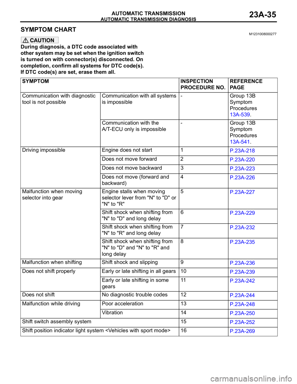
SYMPTOM CHART M1231008000277
During diagnosis, a DTC code associated with
other system may be set when the ignition switch
is turned on with connector(s) disconnected. On
completion, confirm all systems for DTC code(s).
If DTC code(s) are set, erase them all.
SYMPTOM INSPECTION
PROCEDURE NO.REFERENCE
PA G E
Communication with diagnostic
tool is not possibleCommunication with all systems
is impossible- Group 13B
Symptom
Procedures
13A-539.
Communication with the
A/T-ECU only is impossible- Group 13B
Symptom
Procedures
13A-541.
Driving impossible Engine does not start 1
P.23A-218
Does not move forward 2
P.23A-220
Does not move backward 3
P.23A-223
Does not move (forward and
backward)4
P.23A-226
Malfunction when moving
selector into gearEngine stalls when moving
selector lever from "N" to "D" or
"N" to "R"5
P.23A-227
Shift shock when shifting from
"N" to "D" and long delay6
P.23A-229
Shift shock when shifting from
"N" to "R" and long delay 7
P.23A-232
Shift shock when shifting from
"N" to "D" and "N" to "R" and
long delay 8
P.23A-235
Malfunction when shifting Shift shock and slipping 9
P.23A-236
Does not shift properly Early or late shifting in all gears 10
P.23A-239
Early or late shifting in some
gears11
P.23A-242
Does not shift No diagnostic trouble codes 12
P.23A-244
Malfunction while driving Poor acceleration 13
P.23A-248
Vibration 14
P.23A-250
Shift switch assembly system 15
P.23A-252
Shift position indicator light system
P.23A-269