Page 788 of 1500

AUTO A/C DIAGNOSIS
HEATER, AIR CONDITIONING AND VENTILATION55-87
STEP 18. Check the air conditioning compressor clutch
operation.
Connect the compressor connector terminal to the battery posi-
tive (+) terminal and ground the battery’s negative (-) terminal
to the compressor unit. At that time, the air conditioning com-
pressor clutch should make a definite operating sound.
Q: Can the sound (click) of the air conditioning
compressor clutch operation be heard?
YES : Go to Step 19.
NO : Replace the compressor magnet clutch. Check that
the air conditioning works normally.
STEP 19. Check the air thermo sensor.
Measure the resistance between connector terminals 1 and 2
under at least two different temperatures. The resistance val-
ues should generally match those in the graph.
NOTE: The temperature at the check should not exceed the
range in the graph.
Q: Is the air thermo sensor in good condition?
YES : Go to Step 20.
NO : Replace the air thermo sensor. Check that the air
conditioning works normally.
STEP 20. Check the ambient air temperature sensor.
Measure the resistance between the sensor terminals under at
least two temperatures. The resistance values should meet the
values shown.
NOTE: The temperature should be within the shown range.
Q: Is the ambient air temperature sensor in good
condition?
YES : Go to Step 22.
NO : Replace the ambient air temperature sensor. Check
that the air conditioning works normally.
Page 805 of 1500

AUTO A/C DIAGNOSIS
HEATER, AIR CONDITIONING AND VENTILATION55-104
INSPECTION PROCEDURE 7: The A/C Indicator Flashes.
.
TECHNICAL DESCRIPTION (COMMENT)
If the A/C indicator flashes, inadequate refrigerant
quantity, the ambient air temperature sensor circuit
or the A/C pressure sensor circuit is suspected.
.
TROUBLESHOOTING HINTS
Malfunction of the A/C pressure sensor
Malfunction of the ambient air temperature sen-
sor
Malfunction of the A/C-ECU
Refer to component locations GROUP-70
Refer to configuration diagrams GROUP-80
Refer to circuit diagrams GROUP-90
DIAGNOSIS
Required Special Tools:
MB991223: Test Harness Set
: Scan Tool (MUT-III Sub Assembly)
MB991824: Vehicle Communication Interface (V.C.I.)
MB991827: MUT-III USB Cable
MB991910: MUT-III Main Harness A (Vehicles with CAN
communication system)
STEP 1. Using scan tool , read the diagnostic trouble code.
Check if an A/C-ECU DTC is set.
(1) Connect scan tool to the data link connector.
(2) Turn the ignition switch to the "ON" position.
(3) Check if the DTC is set.
(4) Turn the ignition switch to the "LOCK" (OFF) position.
Q: Is the check result satisfactory?
YES : Go to Step 2.
NO : Refer to DIAGNOSTIC TROUBLE CODE CHART
P.55-9.
Page 839 of 1500

AUTO A/C DIAGNOSIS
HEATER, AIR CONDITIONING AND VENTILATION55-138
16 Potentiometer power supply Ignition switch: ON 5 V
17 Power transistor (BASE) When the blower speed
selection dial shows Maximum
air volume.1 V
18 Power transistor
(COLLECTOR)When the blower speed
selection dial shows Maximum
air volume.12.1 V
19 Photo sensor Ignition switch: ON 5 V
20 Sensors and potentiometers
groundAlways 0 V
21 Mode selection damper control
motor potentiometer inputWhen the damper is moved to
the FACE position. 4 V
22 Interior temperature sensor Ignition switch: ON 5 V
23 Ambient temperature sensor
inputWhen sensor temperature is
25
C (77F) [4 k]1.9 V
24 Air thermo sensor input When sensor temperature is
25
C (77F) [1.5 k]2.2 V
25 Photo sensor ground Ignition switch: ON 0 V
26 A/C pressure sensor at 2.6 MPa 3.9 V
27 Ground Always 0 V
28 Power supply to the ignition
switch (IG2)Ignition switch: ON Battery positive voltage
29 Air mixing damper control motor
potentiometer inputWhen the damper door is
moved to the MAX. HOT
position.1.4 V
30 Illumination ground Always 0 V
31 ILL power supply Lighting switch: ON Battery positive voltage
34 A/C pressure sensor ground Always 0 V
36 Power supply to the ignition
switch (ACC)Ignition switch: ON Battery positive voltage TERMINAL
NO.CHECK ITEM CHECKING REQUIREMENTS NORMAL CONDITION
Page 863 of 1500
Page 864 of 1500
AMBIENT TEMPERATURE SENSOR
HEATER, AIR CONDITIONING AND VENTILATION55-163
INSPECTIONM1551006300349.
AMBIENT AIR TEMPERATURE SENSOR CHECK
The ambient air temperature sensor should be checked
without removing it from bumper. If the sensor is removed,
damage will occur to clip rendering it unserviceable.
Measure the resistance between the sensor terminals under at
least two temperatures. The resistance values should meet the
values shown.
NOTE: The temperature should be within the shown range.
Page 887 of 1500
INSPECTION TERMINAL
COMPONENT LOCATIONS70-8
INSPECTION TERMINALM1701000200354
SENSORM1701000600415
NAME SYMBOL NAME SYMBOL
A/C pressure sensor I Interior temperature sensor
A/C>S
A/T control solenoid valve assembly
(Incorporating transmission fluid
temperature sensor)N Knock sensor C
Accelerator pedal position sensor R Left bank heated oxygen sensor (front)
<3.8L Engine>P
Air thermo sensor T Left bank heated oxygen sensor (rear)
<3.8L Engine>P
Ambient temperature sensor L Manifold absolute pressure sensor B
Camshaft position sensor D Mass airflow sensor G
Crankshaft position sensor A Sunroof assembly (Incorporating pulse
sensor)U
Fuel pump module (Incorporating fuel
level sensor (main) and fuel tank
temperature sensor)W Output shaft speed sensor H
Fuel level sensor (sub) V Photo sensor Q
Right bank heated oxygen sensor
(front) <3.8L Engine>O
Input shaft speed sensor K Right bank heated oxygen sensor (rear)
<3.8L Engine>O
Page 1496 of 1500

AUTOMATIC TRANSMISSION DIAGNOSIS
AUTOMATIC TRANSMISSION23A-37
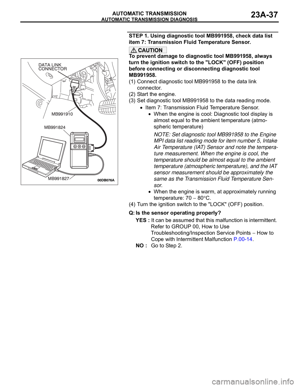
STEP 1. Using diagnostic tool MB991958, check data list
item 7: Transmission Fluid Temperature Sensor.
To prevent damage to diagnostic tool MB991958, always
turn the ignition switch to the "LOCK" (OFF) position
before connecting or disconnecting diagnostic tool
MB991958.
(1) Connect diagnostic tool MB991958 to the data link
connector.
(2) Start the engine.
(3) Set diagnostic tool MB991958 to the data reading mode.
Item 7: Transmission Fluid Temperature Sensor.
When the engine is cool: Diagnostic tool display is
almost equal to the ambient temperature (atmo-
spheric temperature)
NOTE: Set diagnostic tool MB991958 to the Engine
MPI data list reading mode for item number 5, Intake
Air Temperature (IAT) Sensor and note the tempera-
ture measurement. When the engine is cool, the
temperature should be almost equal to the ambient
temperature (atmospheric temperature), and the IAT
sensor measurement should be approximately the
same as the Transmission Fluid Temperature Sen-
sor.
When the engine is warm, at approximately running
temperature: 70
80C.
(4) Turn the ignition switch to the "LOCK" (OFF) position.
Q: Is the sensor operating properly?
YES : It can be assumed that this malfunction is intermittent.
Refer to GROUP 00, How to Use
Troubleshooting/Inspection Service Points
How to
Cope with Intermittent Malfunction P.00-14.
NO : Go to Step 2.
Page 1500 of 1500

AUTOMATIC TRANSMISSION DIAGNOSIS
AUTOMATIC TRANSMISSION23A-41
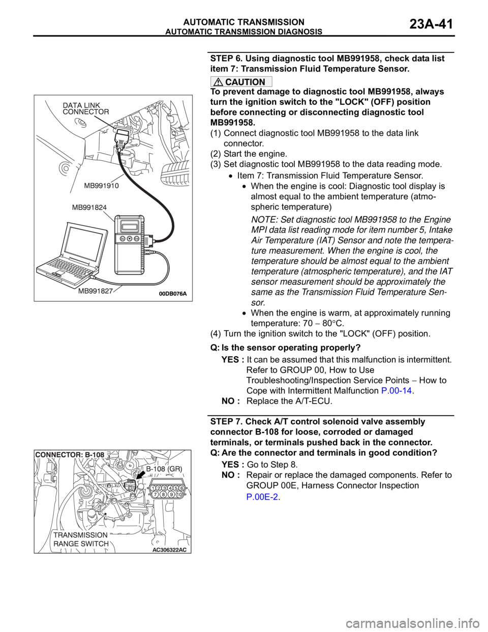
STEP 6. Using diagnostic tool MB991958, check data list
item 7: Transmission Fluid Temperature Sensor.
To prevent damage to diagnostic tool MB991958, always
turn the ignition switch to the "LOCK" (OFF) position
before connecting or disconnecting diagnostic tool
MB991958.
(1) Connect diagnostic tool MB991958 to the data link
connector.
(2) Start the engine.
(3) Set diagnostic tool MB991958 to the data reading mode.
Item 7: Transmission Fluid Temperature Sensor.
When the engine is cool: Diagnostic tool display is
almost equal to the ambient temperature (atmo-
spheric temperature)
NOTE: Set diagnostic tool MB991958 to the Engine
MPI data list reading mode for item number 5, Intake
Air Temperature (IAT) Sensor and note the tempera-
ture measurement. When the engine is cool, the
temperature should be almost equal to the ambient
temperature (atmospheric temperature), and the IAT
sensor measurement should be approximately the
same as the Transmission Fluid Temperature Sen-
sor.
When the engine is warm, at approximately running
temperature: 70
80C.
(4) Turn the ignition switch to the "LOCK" (OFF) position.
Q: Is the sensor operating properly?
YES : It can be assumed that this malfunction is intermittent.
Refer to GROUP 00, How to Use
Troubleshooting/Inspection Service Points
How to
Cope with Intermittent Malfunction P.00-14.
NO : Replace the A/T-ECU.
STEP 7. Check A/T control solenoid valve assembly
connector B-108 for loose, corroded or damaged
terminals, or terminals pushed back in the connector.
Q: Are the connector and terminals in good condition?
YES : Go to Step 8.
NO : Repair or replace the damaged components. Refer to
GROUP 00E, Harness Connector Inspection
P.00E-2.