2005 MERCEDES-BENZ SPRINTER low oil pressure
[x] Cancel search: low oil pressurePage 164 of 1232
HEATED SEAT RELAY
DESCRIPTION
The heated seat relay is an electromechanical
device that switches 12v battery current to the
heated seat elements when the relay control coil is
energized. The heated seat relay is located in the
Fuse Block, under the drivers seat. The heated seat
relay is a International Standards Organization
(ISO) relay. Relays conforming to the ISO specifica-
tions have common physical dimensions, current
capacities, terminal patterns, and terminal functions.
The heated seat relay cannot be repaired or
adjusted and, if faulty or damaged, it must be
replaced.
OPERATION
The ISO relay consists of an electromagnetic coil, a
resistor or diode, and three (two fixed and one mov-
able) electrical contacts. The movable (common feed)
relay contact is held against one of the fixed contacts
(normally closed) by spring pressure. When the elec-
tromagnetic coil is energized, it draws the movable
contact away from the normally closed fixed contact,
and holds it against the other (normally open) fixed
contact. When the electromagnetic coil is de-ener-
gized, spring pressure returns the movable contact to
the normally closed position. The resistor or diode is
connected in parallel with the electromagnetic coil in
the relay, and helps to dissipate voltage spikes that
are produced when the coil is de-energized.
DIAGNOSIS AND TESTING - HEATED SEAT
RELAY
The heated seat relay is located in the Fuse Block,
under the drivers seat. Refer toWiringfor the loca-
tion of complete heated seat system wiring diagrams.
(1) Remove the heated seat relay from the fuse
block.
(2) A relay in the de-energized position should
have continuity between terminals 87A and 30, and
no continuity between terminals 87 and 30. If OK, go
to Step 3. If not OK, replace the faulty relay.
(3) Resistance between terminals 85 and 86 (elec-
tromagnet) should be 75 5 ohms. If OK, go to Step
4. If not OK, replace the faulty relay.
(4) Connect a battery to terminals 85 and 86.
There should now be continuity between terminals
30 and 87, and no continuity between terminals 87A
and 30. If OK, check the relay supply circuits. If not
OK, replace the faulty relay.
REMOVAL
(1) Disconnect and isolate the battery negative
cable.
(2) The heated seat relay is located in the fuse
block, under the drivers seat. Refer to wiring for
detailed location.
(3) Grasp the heated seat relay firmly and pull it
straight out from the fuse block. A slight rocking
motion will aid in removal.
INSTALLATION
(1) Grasp the heated seat relay firmly and push it
straight in the fuse block.
(2) Reconnect the battery negative cable.
HEATED SEAT SENSOR
DESCRIPTION
The heated seat temperature sensor is a Negative
Temperature Coefficient (NTC) thermistor. One tem-
perature sensor is used for each seat. The sensor is
located in the seat cushion heating element for all
models.
The heated seat sensor cannot be adjusted or
repaired and if it is found to be faulty, the complete
heated seat element must be replaced.
DIAGNOSIS AND TESTING - HEATED SEAT
SENSOR
For complete circuit diagrams, refer toWiring.
NOTE: Any resistance values (ohmsV) given in the
following text are supplied using the automatic
range generated by a FLUKETautomotive meter. If
another type of measuring device is used the val-
ues generated may not be the same as the results
shown here, or may have to be converted to the
range used here.
(1) Backprobe the heated seat relay wire harness
connector, do not disconnect. Using an voltmeter,
check the voltage of the seat temperature sensor
input cavity of the heated seat relay wire harness
connector. The seat sensor input voltage should be
between 1.7 volts and 3.0 volts with the system ON.
If OK, sensor is OK at this time. If not OK, replace
the faulty seat cushion heating element and sensor
assembly.
8G - 4 HEATED SYSTEMSVA
Page 303 of 1232
²85 (Coil Ground)- This terminal is connected
to the ground feed side of the relay control coil.
²86 (Coil Battery)- This terminal is connected
to the battery feed side of the relay control coil.
²87 (Normally Open)- This terminal is con-
nected to the normally open fixed contact point of the
relay.
²87A (Normally Closed)- This terminal is con-
nected to the normally closed fixed contact point of
the relay.
The wiper relay cannot be adjusted or repaired. If
the relay is damaged or faulty, it must be replaced.
OPERATION
The wiper relay (or intermittent wipe relay) is an
electromechanical switch that uses a low current
input from the intermittent wipe logic circuitry
within the fuse block underneath the steering column
to control a high current output to the low speed
brush of the wiper motor. The movable common feed
contact point is held against the fixed normally
closed contact point by spring pressure. When the
relay coil is energized, an electromagnetic field is
produced by the coil windings. This electromagnetic
field draws the movable relay contact point away
from the fixed normally closed contact point, and
holds it against the fixed normally open contact
point. When the relay coil is de-energized, spring
pressure returns the movable contact point back
against the fixed normally closed contact point. A
resistor or diode is connected in parallel with the
relay coil in the relay, and helps to dissipate voltage
spikes and electromagnetic interference that can be
generated as the electromagnetic field of the relay
coil collapses.The wiper relay terminals are connected to the
vehicle electrical system through a connector recepta-
cle in the fuse block. The inputs and outputs of the
wiper relay include:
²The common feed terminal (30) provides an out-
put to the wiper motor low speed brush through the
wiper control circuitry of the multi-function switch on
the steering column. When the wiper relay is de-en-
ergized, the common feed terminal is connected to
the input of the relay normally closed terminal (87).
When the wiper relay is energized, the common feed
terminal is connected to the input of the relay nor-
mally open terminal (87A).
²The coil ground terminal (85) is connected to
battery current through a fused ignition switch out-
put circuit whenever the ignition switch is in the On
position.
²The coil battery terminal (86) is connected to the
relay control output of the wiper, turn signals and
engine start control module within the fuse block
through the wiper relay control circuit. This elec-
tronic circuitry controls the ground path for this cir-
cuit internally to energize or de-energize the wiper
relay control coil based upon its programming and
inputs from the wiper and washer control circuitry of
the multi-function switch, the wiper motor park
switch, and the ignition switch.
²The normally open terminal (87) is connected to
the output of the wiper motor park switch through
the wiper motor park switch sense circuit. This cir-
cuit can carry either battery current (wipers are not
in park position) or ground (wipers are in park posi-
tion), depending upon the status of the wiper park
switch.
²The normally closed terminal (87A) is connected
to battery current through a fused ignition switch
output circuit whenever the ignition switch is in the
On position.
The wiper relay can be diagnosed using conven-
tional diagnostic tools and methods.
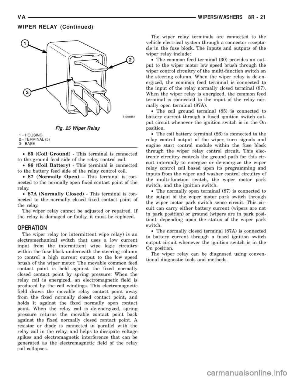
Fig. 25 Wiper Relay
1 - HOUSING
2 - TERMINAL (5)
3 - BASE
VAWIPERS/WASHERS 8R - 21
WIPER RELAY (Continued)
Page 317 of 1232
8W-02 COMPONENT INDEX
Component Page
A/C Auxiliary Fan Relay................ 8W-42
A/C Auxiliary Fan..................... 8W-42
A/C Compressor Clutch................. 8W-42
A/C Control Module-Roof................ 8W-42
A/C Fan Switch....................... 8W-42
A/C Switch-Roof...................... 8W-42
Accelerator Pedal Position Sensor......... 8W-30
Air Outlet Temperature Sensor........... 8W-42
Airbag Control Module................. 8W-43
Airbag Squibs........................ 8W-43
Ambient Temperature Sensor............ 8W-42
Ash Receiver Lamp.................... 8W-44
Automatic Temperature Control Module.... 8W-42
Auxiliary Heater Relay................. 8W-42
Auxiliary Heater Switch................ 8W-42
Battery Relay-Auxiliary................ 8W-20
Batteries............................ 8W-20
Beam Select Switch.................... 8W-50
Blower Motors........................ 8W-42
Body Plug Connector................... 8W-11
Boost Pressure Sensor.................. 8W-30
Boost Pressure Solenoid................ 8W-30
Brake Fluid Level Switch............... 8W-35
Brake Lamp Switch.................... 8W-35
Brake Wear Sensors................... 8W-35
Cabin Heater Assembly................. 8W-42
Cabin Heater Control Module............ 8W-42
Camshaft Position Sensor............... 8W-30
Center High Mounted Stop Lamp......... 8W-51
Central Timer Module.................. 8W-45
Cigar Lighter Lamp................... 8W-44
Cigar Lighter......................... 8W-41
Circulation Pump Diode................ 8W-42
Circulation Pump Relay................ 8W-42
Circulation Pump..................... 8W-42
Clockspring....................... 8W-41, 43
Contact Switch Door-Tailgate............ 8W-44
Controller Antilock Brake............... 8W-35
Courtesy Lamps...................... 8W-44
Crankcase Heater..................... 8W-30
Crankshaft Position Sensor.............. 8W-30
Ctel Antenna Connector................ 8W-55
Ctel Connector..................... 8W-47, 55
Cylinder Lock Switch-Driver............. 8W-61
D+ Relay No. 1....................... 8W-10
D+ Relay No. 2....................... 8W-11
Data Link Connector................... 8W-18
Daytime Running Lamp Relays........... 8W-50
Differential Lock Solenoid Valve.......... 8W-31
Dome Lamp.......................... 8W-44
Door Jamb Switches................... 8W-44
Door Lock Motor/Ajar Switch Assemblies . . . 8W-61Component Page
Dosing Pump......................... 8W-42
EGR Valve........................... 8W-30
Engine Control Module................. 8W-30
Engine Control Relay.................. 8W-31
Engine Coolant Level Switch............. 8W-30
Engine Coolant Temperature Sensor....... 8W-30
Engine Oil Sensor..................... 8W-30
Evaporator Temperature Sensor.......... 8W-42
Fan Stage 1 Relay..................... 8W-42
Fog Lamp Relay...................... 8W-50
Fog Lamp Switch..................... 8W-50
Fuel Injectors........................ 8W-30
Fuel Level Sensor..................... 8W-30
Fuel Pressure Sensor.................. 8W-30
Fuel Pressure Solenoid................. 8W-30
Fuel Shutdown Solenoid................ 8W-30
Fuel Temperature Sensor............... 8W-30
Fuses............................ 8W-10, 11
Fuse Blocks.......................... 8W-10
Fuse/Relay Block...................... 8W-11
Fused Ignition Switch Run-Start Relay..... 8W-11
Grounds............................ 8W-70
Generator........................... 8W-20
Glow Plug Control Module.............. 8W-30
Glow Plugs.......................... 8W-30
Hazard Warning Switch................ 8W-52
Headlamp Adjust Switch................ 8W-50
Headlamp Assemblies............... 8W-50, 52
Headlamp Switch..................... 8W-50
Heat Exchanger Connector.............. 8W-42
Heat Exchanger Switch................. 8W-42
Heated Seat Modules.................. 8W-63
Heated Seat Switches.................. 8W-63
Heater Timer-Auxiliary................. 8W-42
Hood Ajar Switch..................... 8W-39
Horn Relay.......................... 8W-41
Horn Switch......................... 8W-41
Horn............................... 8W-41
Ignition Lock Switch................... 8W-40
Ignition Switch....................... 8W-10
Instrument Cluster.................... 8W-40
Instrument Panel Socket................ 8W-40
Intake Air Temperature Sensor........... 8W-30
Interior Lamps....................... 8W-44
Interior Light Switches................. 8W-44
Interior Lighting Connector.............. 8W-44
Intrusion Sensors..................... 8W-39
Kickdown Switch...................... 8W-30
Lamp Relays......................... 8W-50
License Plate Lamps................... 8W-51
Locker Switches...................... 8W-31
Low Fuel Pressure Sensor............... 8W-30
VA8W-02 COMPONENT INDEX 8W - 02 - 1
Page 435 of 1232
8W-30 FUEL/IGNITION SYSTEM
Component Page
Accelerator Pedal Position Sensor....... 8W-30-8
Airbag Control Module................ 8W-30-7
Automatic Temperature Control
Module........................ 8W-30-2, 3
Boost Pressure Sensor................ 8W-30-7
Boost Pressure Solenoid............... 8W-30-6
Camshaft Position Sensor............. 8W-30-16
Central Timer Module................ 8W-30-7
Controller Antilock Brake............ 8W-30-2, 3
Crankcase Heater................... 8W-30-12
Crankshaft Position Sensor........... 8W-30-14
Data Link Connector................ 8W-30-17
EGR Valve........................ 8W-30-12
Engine Control Module . 8W-30-2, 3, 4, 5, 6, 7, 8, 9,
10, 11, 12, 13, 14, 15, 16, 17
Engine Control Relay.............. 8W-30-12, 9
Engine Coolant Level Switch.......... 8W-30-17
Engine Coolant Temperature Sensor.... 8W-30-16
Engine Oil Sensor................... 8W-30-12
Fuel Injector No. 1.................. 8W-30-10
Fuel Injector No. 2.................. 8W-30-11
Fuel Injector No. 3.................. 8W-30-10
Fuel Injector No. 4.................. 8W-30-10
Fuel Injector No. 5.................. 8W-30-11
Fuel Level Sensor................... 8W-30-17
Fuel Pressure Sensor................ 8W-30-15
Fuel Pressure Solenoid............... 8W-30-14
Fuel Shutdown Solenoid.............. 8W-30-14
Fuel Temperature Sensor............. 8W-30-15Component Page
Fuse 5............................ 8W-30-5
Fuse 16............................ 8W-30-9
Fuse 17........................... 8W-30-12
Fuse 18............................ 8W-30-7
Fuse Block No. 1................ 8W-30-7, 9, 12
G100........................... 8W-30-5, 17
G200.............................. 8W-30-9
Glow Plug Control Module............. 8W-30-5
Glow Plug No. 1..................... 8W-30-5
Glow Plug No. 2..................... 8W-30-5
Glow Plug No. 3..................... 8W-30-5
Glow Plug No. 4..................... 8W-30-5
Glow Plug No. 5..................... 8W-30-5
Instrument Cluster.............. 8W-30-2, 3, 17
Intake Air Temperature Sensor......... 8W-30-8
Kickdown Switch.................... 8W-30-4
Low Fuel Pressure Sensor............ 8W-30-13
Mass Air Flow Sensor................. 8W-30-6
Power Distribution Center............. 8W-30-5
Sensor........................... 8W-30-13
Sentry Key Remote Entry Module..... 8W-30-2, 3
Shifter Assembly.................. 8W-30-2, 3
Speed Control Switch................. 8W-30-4
Starter Motor Relay................. 8W-30-17
Transmission Control Module......... 8W-30-2, 3
Water In Fuel Sensor................ 8W-30-13
Wiper/Turn Signal/Engine Start Control
Module.......................... 8W-30-9
VA8W-30 FUEL/IGNITION SYSTEM 8W - 30 - 1
Page 628 of 1232
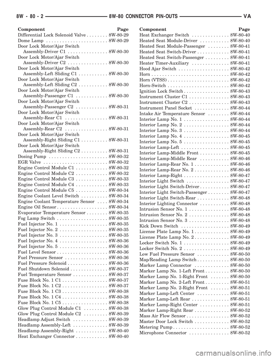
Component Page
Differential Lock Solenoid Valve........ 8W-80-29
Dome Lamp....................... 8W-80-29
Door Lock Motor/Ajar Switch
Assembly-Driver C1............... 8W-80-30
Door Lock Motor/Ajar Switch
Assembly-Driver C2............... 8W-80-30
Door Lock Motor/Ajar Switch
Assembly-Left Sliding C1........... 8W-80-30
Door Lock Motor/Ajar Switch
Assembly-Left Sliding C2........... 8W-80-30
Door Lock Motor/Ajar Switch
Assembly-Passenger C1............ 8W-80-30
Door Lock Motor/Ajar Switch
Assembly-Passenger C2............ 8W-80-31
Door Lock Motor/Ajar Switch
Assembly-Rear C1................ 8W-80-31
Door Lock Motor/Ajar Switch
Assembly-Rear C2................ 8W-80-31
Door Lock Motor/Ajar Switch
Assembly-Right Sliding C1.......... 8W-80-31
Door Lock Motor/Ajar Switch
Assembly-Right Sliding C2.......... 8W-80-31
Dosing Pump...................... 8W-80-32
EGR Valve........................ 8W-80-32
Engine Control Module C1............ 8W-80-32
Engine Control Module C2............ 8W-80-32
Engine Control Module C3............ 8W-80-33
Engine Control Module C4............ 8W-80-33
Engine Control Module C5............ 8W-80-34
Engine Coolant Level Switch.......... 8W-80-34
Engine Coolant Temperature Sensor.... 8W-80-34
Engine Oil Sensor................... 8W-80-34
Evaporator Temperature Sensor........ 8W-80-35
Fog Lamp Switch................... 8W-80-35
Fuel Injector No. 1.................. 8W-80-35
Fuel Injector No. 2.................. 8W-80-35
Fuel Injector No. 3.................. 8W-80-35
Fuel Injector No. 4.................. 8W-80-36
Fuel Injector No. 5.................. 8W-80-36
Fuel Level Sensor................... 8W-80-36
Fuel Pressure Sensor................ 8W-80-36
Fuel Pressure Solenoid............... 8W-80-36
Fuel Shutdown Solenoid.............. 8W-80-37
Fuel Temperature Sensor............. 8W-80-37
Fuse Block No. 1 C1................. 8W-80-37
Fuse Block No. 1 C2................. 8W-80-37
Fuse Block No. 1 C3................. 8W-80-38
Fuse Block No. 1 C4................. 8W-80-38
Fuse Block No. 1 C5................. 8W-80-38
Glow Plug Control Module C1......... 8W-80-38
Glow Plug Control Module C2......... 8W-80-39
Headlamp Adjust Switch............. 8W-80-39
Headlamp Assembly-Left............. 8W-80-39
Headlamp Assembly-Right............ 8W-80-40
Heat Exchanger Connector............ 8W-80-40Component Page
Heat Exchanger Switch.............. 8W-80-40
Heated Seat Module-Driver........... 8W-80-40
Heated Seat Module-Passenger........ 8W-80-41
Heated Seat Switch-Driver............ 8W-80-41
Heated Seat Switch-Passenger......... 8W-80-41
Heater Timer-Auxiliary.............. 8W-80-41
Hood Ajar Switch................... 8W-80-42
Horn............................. 8W-80-42
Horn (VTSS)....................... 8W-80-42
Horn-Switch....................... 8W-80-42
Ignition Lock Switch................. 8W-80-43
Instrument Cluster C1............... 8W-80-43
Instrument Cluster C2............... 8W-80-43
Instrument Panel Socket............. 8W-80-44
Intake Air Temperature Sensor........ 8W-80-44
Interior Lamp No. 1................. 8W-80-44
Interior Lamp No. 2................. 8W-80-44
Interior Lamp No. 3................. 8W-80-44
Interior Lamp No. 4................. 8W-80-45
Interior Lamp No. 5................. 8W-80-45
Interior Lamp-Left.................. 8W-80-45
Interior Lamp-Middle Front........... 8W-80-45
Interior Lamp-Middle Rear........... 8W-80-46
Interior Lamp-Rear No. 1............. 8W-80-46
Interior Lamp-Rear No. 2............. 8W-80-46
Interior Lamp-Right................. 8W-80-47
Interior Light Switch................ 8W-80-47
Interior Light Switch-Driver........... 8W-80-47
Interior Light Switch-Passenger........ 8W-80-47
Interior Light Switch-Rear............ 8W-80-48
Interior Lighting Connector........... 8W-80-48
Intrusion Sensor No. 1............... 8W-80-48
Intrusion Sensor No. 2............... 8W-80-48
Intrusion Sensor No. 3............... 8W-80-48
Kick Down Switch.................. 8W-80-49
License Plate Lamp No. 1............. 8W-80-49
License Plate Lamp No. 2............. 8W-80-49
Locker Switch No. 1................. 8W-80-49
Locker Switch No. 2................. 8W-80-49
Low Fuel Pressure Sensor............ 8W-80-50
Map/Reading Lamp Switch............ 8W-80-50
Marker Lamp Connector............. 8W-80-50
Marker Lamp No. 1-Left Front......... 8W-80-50
Marker Lamp No. 1-Right Front....... 8W-80-50
Marker Lamp No. 2-Left Front......... 8W-80-51
Marker Lamp No. 2-Right Front....... 8W-80-51
Marker Lamp-Left Center............ 8W-80-51
Marker Lamp-Left Rear.............. 8W-80-51
Marker Lamp-Right Center........... 8W-80-51
Marker Lamp-Right Rear............. 8W-80-52
Mass Air Flow Sensor................ 8W-80-52
Master Door Lock Switch............. 8W-80-52
Metering Pump..................... 8W-80-52
Microphone Connector............... 8W-80-52
8W - 80 - 2 8W-80 CONNECTOR PIN-OUTSVA
Page 659 of 1232
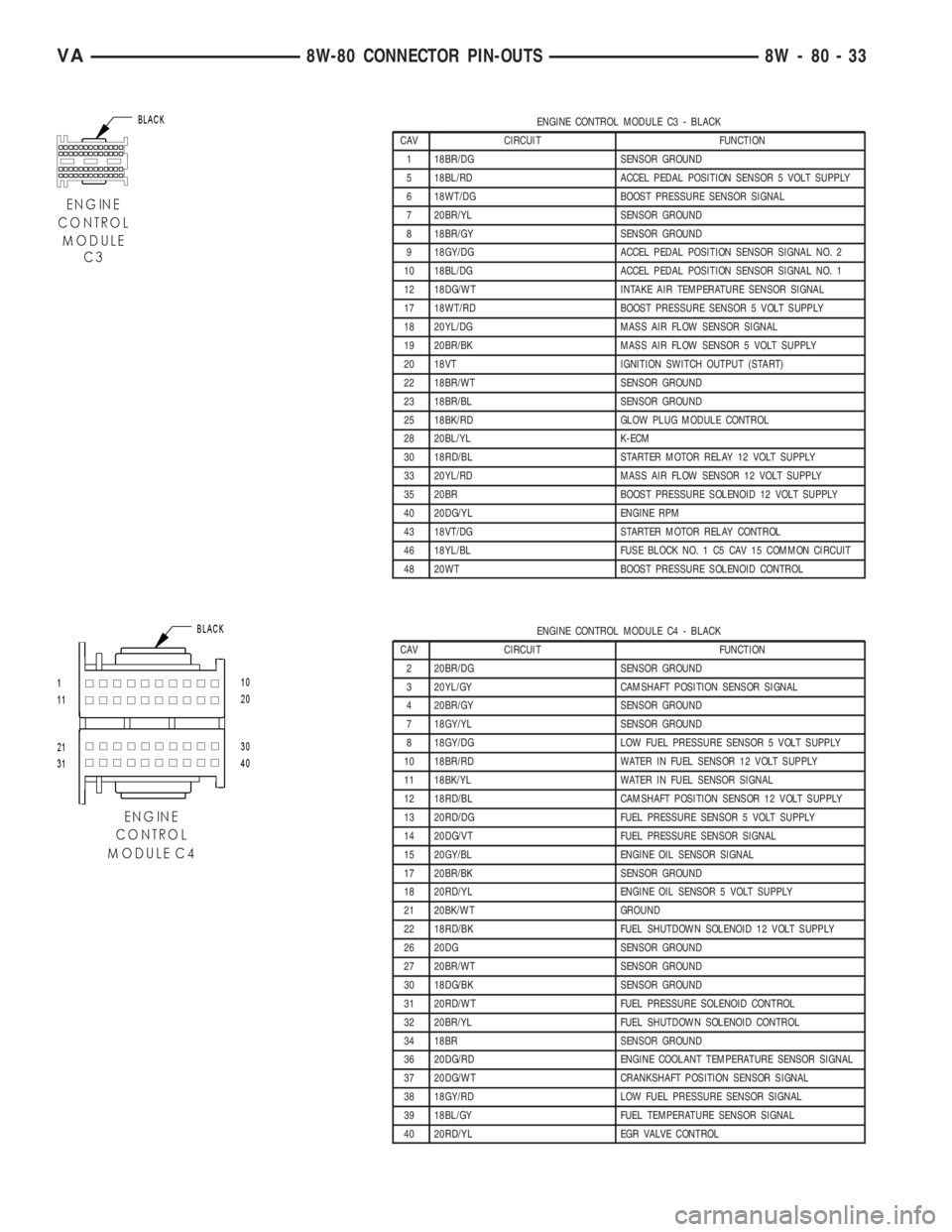
ENGINE CONTROL MODULE C3 - BLACK
CAV CIRCUIT FUNCTION
1 18BR/DG SENSOR GROUND
5 18BL/RD ACCEL PEDAL POSITION SENSOR 5 VOLT SUPPLY
6 18WT/DG BOOST PRESSURE SENSOR SIGNAL
7 20BR/YL SENSOR GROUND
8 18BR/GY SENSOR GROUND
9 18GY/DG ACCEL PEDAL POSITION SENSOR SIGNAL NO. 2
10 18BL/DG ACCEL PEDAL POSITION SENSOR SIGNAL NO. 1
12 18DG/WT INTAKE AIR TEMPERATURE SENSOR SIGNAL
17 18WT/RD BOOST PRESSURE SENSOR 5 VOLT SUPPLY
18 20YL/DG MASS AIR FLOW SENSOR SIGNAL
19 20BR/BK MASS AIR FLOW SENSOR 5 VOLT SUPPLY
20 18VT IGNITION SWITCH OUTPUT (START)
22 18BR/WT SENSOR GROUND
23 18BR/BL SENSOR GROUND
25 18BK/RD GLOW PLUG MODULE CONTROL
28 20BL/YL K-ECM
30 18RD/BL STARTER MOTOR RELAY 12 VOLT SUPPLY
33 20YL/RD MASS AIR FLOW SENSOR 12 VOLT SUPPLY
35 20BR BOOST PRESSURE SOLENOID 12 VOLT SUPPLY
40 20DG/YL ENGINE RPM
43 18VT/DG STARTER MOTOR RELAY CONTROL
46 18YL/BL FUSE BLOCK NO. 1 C5 CAV 15 COMMON CIRCUIT
48 20WT BOOST PRESSURE SOLENOID CONTROL
ENGINE CONTROL MODULE C4 - BLACK
CAV CIRCUIT FUNCTION
2 20BR/DG SENSOR GROUND
3 20YL/GY CAMSHAFT POSITION SENSOR SIGNAL
4 20BR/GY SENSOR GROUND
7 18GY/YL SENSOR GROUND
8 18GY/DG LOW FUEL PRESSURE SENSOR 5 VOLT SUPPLY
10 18BR/RD WATER IN FUEL SENSOR 12 VOLT SUPPLY
11 18BK/YL WATER IN FUEL SENSOR SIGNAL
12 18RD/BL CAMSHAFT POSITION SENSOR 12 VOLT SUPPLY
13 20RD/DG FUEL PRESSURE SENSOR 5 VOLT SUPPLY
14 20DG/VT FUEL PRESSURE SENSOR SIGNAL
15 20GY/BL ENGINE OIL SENSOR SIGNAL
17 20BR/BK SENSOR GROUND
18 20RD/YL ENGINE OIL SENSOR 5 VOLT SUPPLY
21 20BK/WT GROUND
22 18RD/BK FUEL SHUTDOWN SOLENOID 12 VOLT SUPPLY
26 20DG SENSOR GROUND
27 20BR/WT SENSOR GROUND
30 18DG/BK SENSOR GROUND
31 20RD/WT FUEL PRESSURE SOLENOID CONTROL
32 20BR/YL FUEL SHUTDOWN SOLENOID CONTROL
34 18BR SENSOR GROUND
36 20DG/RD ENGINE COOLANT TEMPERATURE SENSOR SIGNAL
37 20DG/WT CRANKSHAFT POSITION SENSOR SIGNAL
38 18GY/RD LOW FUEL PRESSURE SENSOR SIGNAL
39 18BL/GY FUEL TEMPERATURE SENSOR SIGNAL
40 20RD/YL EGR VALVE CONTROL
VA8W-80 CONNECTOR PIN-OUTS 8W - 80 - 33
Page 737 of 1232
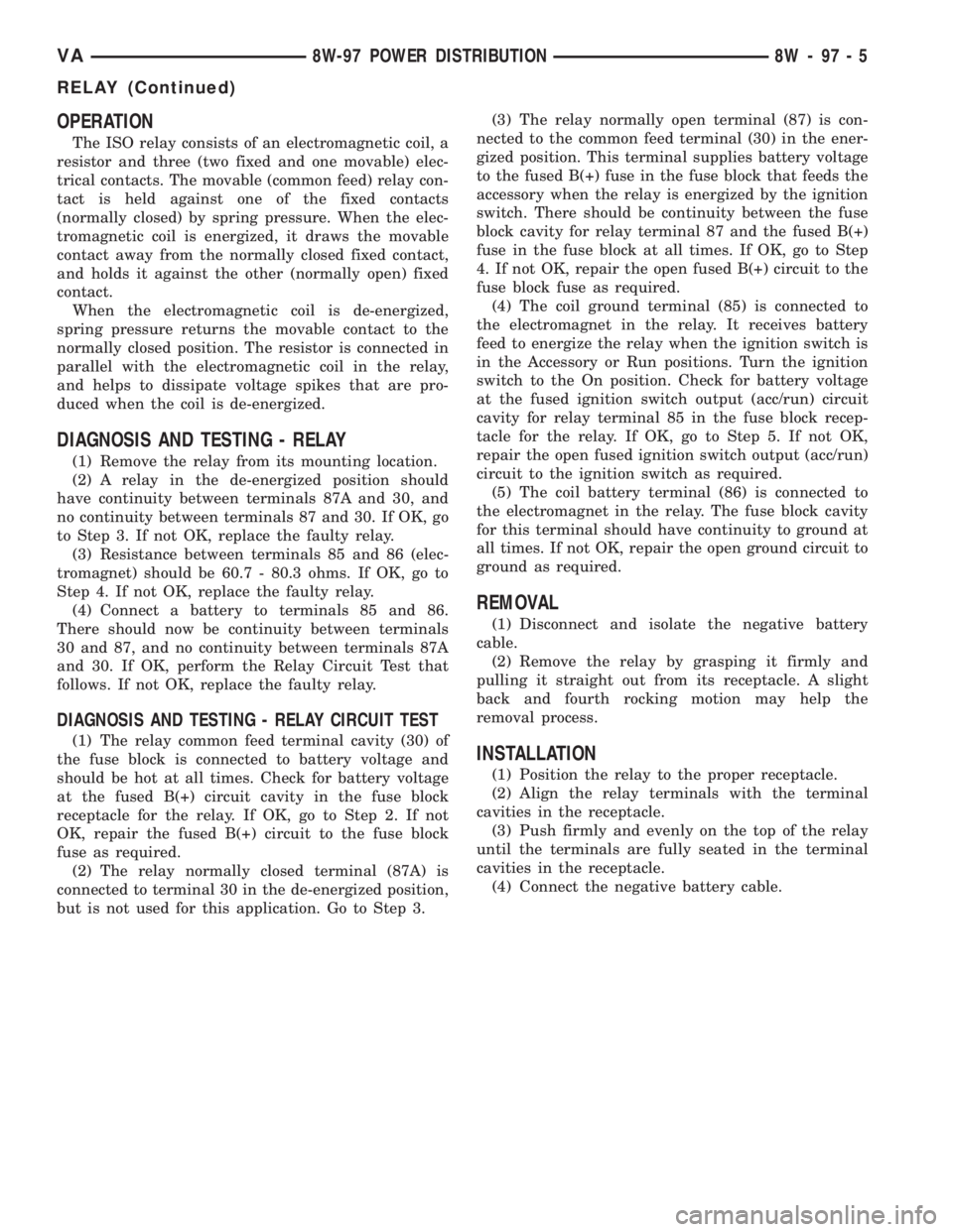
OPERATION
The ISO relay consists of an electromagnetic coil, a
resistor and three (two fixed and one movable) elec-
trical contacts. The movable (common feed) relay con-
tact is held against one of the fixed contacts
(normally closed) by spring pressure. When the elec-
tromagnetic coil is energized, it draws the movable
contact away from the normally closed fixed contact,
and holds it against the other (normally open) fixed
contact.
When the electromagnetic coil is de-energized,
spring pressure returns the movable contact to the
normally closed position. The resistor is connected in
parallel with the electromagnetic coil in the relay,
and helps to dissipate voltage spikes that are pro-
duced when the coil is de-energized.
DIAGNOSIS AND TESTING - RELAY
(1) Remove the relay from its mounting location.
(2) A relay in the de-energized position should
have continuity between terminals 87A and 30, and
no continuity between terminals 87 and 30. If OK, go
to Step 3. If not OK, replace the faulty relay.
(3) Resistance between terminals 85 and 86 (elec-
tromagnet) should be 60.7 - 80.3 ohms. If OK, go to
Step 4. If not OK, replace the faulty relay.
(4) Connect a battery to terminals 85 and 86.
There should now be continuity between terminals
30 and 87, and no continuity between terminals 87A
and 30. If OK, perform the Relay Circuit Test that
follows. If not OK, replace the faulty relay.
DIAGNOSIS AND TESTING - RELAY CIRCUIT TEST
(1) The relay common feed terminal cavity (30) of
the fuse block is connected to battery voltage and
should be hot at all times. Check for battery voltage
at the fused B(+) circuit cavity in the fuse block
receptacle for the relay. If OK, go to Step 2. If not
OK, repair the fused B(+) circuit to the fuse block
fuse as required.
(2) The relay normally closed terminal (87A) is
connected to terminal 30 in the de-energized position,
but is not used for this application. Go to Step 3.(3) The relay normally open terminal (87) is con-
nected to the common feed terminal (30) in the ener-
gized position. This terminal supplies battery voltage
to the fused B(+) fuse in the fuse block that feeds the
accessory when the relay is energized by the ignition
switch. There should be continuity between the fuse
block cavity for relay terminal 87 and the fused B(+)
fuse in the fuse block at all times. If OK, go to Step
4. If not OK, repair the open fused B(+) circuit to the
fuse block fuse as required.
(4) The coil ground terminal (85) is connected to
the electromagnet in the relay. It receives battery
feed to energize the relay when the ignition switch is
in the Accessory or Run positions. Turn the ignition
switch to the On position. Check for battery voltage
at the fused ignition switch output (acc/run) circuit
cavity for relay terminal 85 in the fuse block recep-
tacle for the relay. If OK, go to Step 5. If not OK,
repair the open fused ignition switch output (acc/run)
circuit to the ignition switch as required.
(5) The coil battery terminal (86) is connected to
the electromagnet in the relay. The fuse block cavity
for this terminal should have continuity to ground at
all times. If not OK, repair the open ground circuit to
ground as required.
REMOVAL
(1) Disconnect and isolate the negative battery
cable.
(2) Remove the relay by grasping it firmly and
pulling it straight out from its receptacle. A slight
back and fourth rocking motion may help the
removal process.
INSTALLATION
(1) Position the relay to the proper receptacle.
(2) Align the relay terminals with the terminal
cavities in the receptacle.
(3) Push firmly and evenly on the top of the relay
until the terminals are fully seated in the terminal
cavities in the receptacle.
(4) Connect the negative battery cable.
VA8W-97 POWER DISTRIBUTION 8W - 97 - 5
RELAY (Continued)
Page 741 of 1232
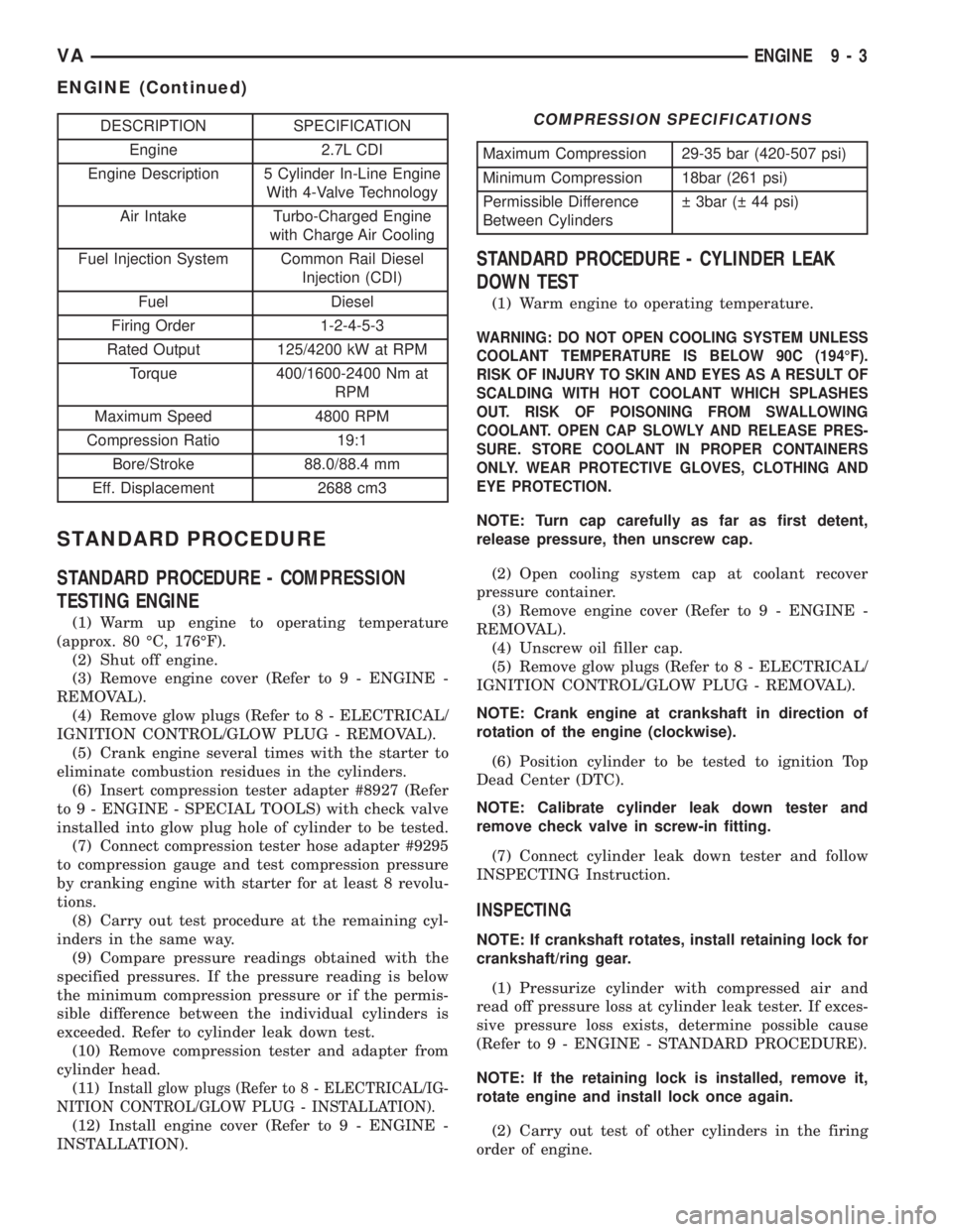
DESCRIPTION SPECIFICATION
Engine 2.7L CDI
Engine Description 5 Cylinder In-Line Engine
With 4-Valve Technology
Air Intake Turbo-Charged Engine
with Charge Air Cooling
Fuel Injection System Common Rail Diesel
Injection (CDI)
Fuel Diesel
Firing Order 1-2-4-5-3
Rated Output 125/4200 kW at RPM
Torque 400/1600-2400 Nm at
RPM
Maximum Speed 4800 RPM
Compression Ratio 19:1
Bore/Stroke 88.0/88.4 mm
Eff. Displacement 2688 cm3
STANDARD PROCEDURE
STANDARD PROCEDURE - COMPRESSION
TESTING ENGINE
(1) Warm up engine to operating temperature
(approx. 80 ÉC, 176ÉF).
(2) Shut off engine.
(3) Remove engine cover (Refer to 9 - ENGINE -
REMOVAL).
(4) Remove glow plugs (Refer to 8 - ELECTRICAL/
IGNITION CONTROL/GLOW PLUG - REMOVAL).
(5) Crank engine several times with the starter to
eliminate combustion residues in the cylinders.
(6) Insert compression tester adapter #8927 (Refer
to 9 - ENGINE - SPECIAL TOOLS) with check valve
installed into glow plug hole of cylinder to be tested.
(7) Connect compression tester hose adapter #9295
to compression gauge and test compression pressure
by cranking engine with starter for at least 8 revolu-
tions.
(8) Carry out test procedure at the remaining cyl-
inders in the same way.
(9) Compare pressure readings obtained with the
specified pressures. If the pressure reading is below
the minimum compression pressure or if the permis-
sible difference between the individual cylinders is
exceeded. Refer to cylinder leak down test.
(10) Remove compression tester and adapter from
cylinder head.
(11)
Install glow plugs (Refer to 8 - ELECTRICAL/IG-
NITION CONTROL/GLOW PLUG - INSTALLATION).
(12) Install engine cover (Refer to 9 - ENGINE -
INSTALLATION).
COMPRESSION SPECIFICATIONS
Maximum Compression 29-35 bar (420-507 psi)
Minimum Compression 18bar (261 psi)
Permissible Difference
Between Cylinders 3bar ( 44 psi)
STANDARD PROCEDURE - CYLINDER LEAK
DOWN TEST
(1) Warm engine to operating temperature.
WARNING: DO NOT OPEN COOLING SYSTEM UNLESS
COOLANT TEMPERATURE IS BELOW 90C (194ÉF).
RISK OF INJURY TO SKIN AND EYES AS A RESULT OF
SCALDING WITH HOT COOLANT WHICH SPLASHES
OUT. RISK OF POISONING FROM SWALLOWING
COOLANT. OPEN CAP SLOWLY AND RELEASE PRES-
SURE. STORE COOLANT IN PROPER CONTAINERS
ONLY. WEAR PROTECTIVE GLOVES, CLOTHING AND
EYE PROTECTION.
NOTE: Turn cap carefully as far as first detent,
release pressure, then unscrew cap.
(2) Open cooling system cap at coolant recover
pressure container.
(3) Remove engine cover (Refer to 9 - ENGINE -
REMOVAL).
(4) Unscrew oil filler cap.
(5) Remove glow plugs (Refer to 8 - ELECTRICAL/
IGNITION CONTROL/GLOW PLUG - REMOVAL).
NOTE: Crank engine at crankshaft in direction of
rotation of the engine (clockwise).
(6) Position cylinder to be tested to ignition Top
Dead Center (DTC).
NOTE: Calibrate cylinder leak down tester and
remove check valve in screw-in fitting.
(7) Connect cylinder leak down tester and follow
INSPECTING Instruction.
INSPECTING
NOTE: If crankshaft rotates, install retaining lock for
crankshaft/ring gear.
(1) Pressurize cylinder with compressed air and
read off pressure loss at cylinder leak tester. If exces-
sive pressure loss exists, determine possible cause
(Refer to 9 - ENGINE - STANDARD PROCEDURE).
NOTE: If the retaining lock is installed, remove it,
rotate engine and install lock once again.
(2) Carry out test of other cylinders in the firing
order of engine.
VAENGINE 9 - 3
ENGINE (Continued)