Page 391 of 464
391 Practical hints
Flat tire
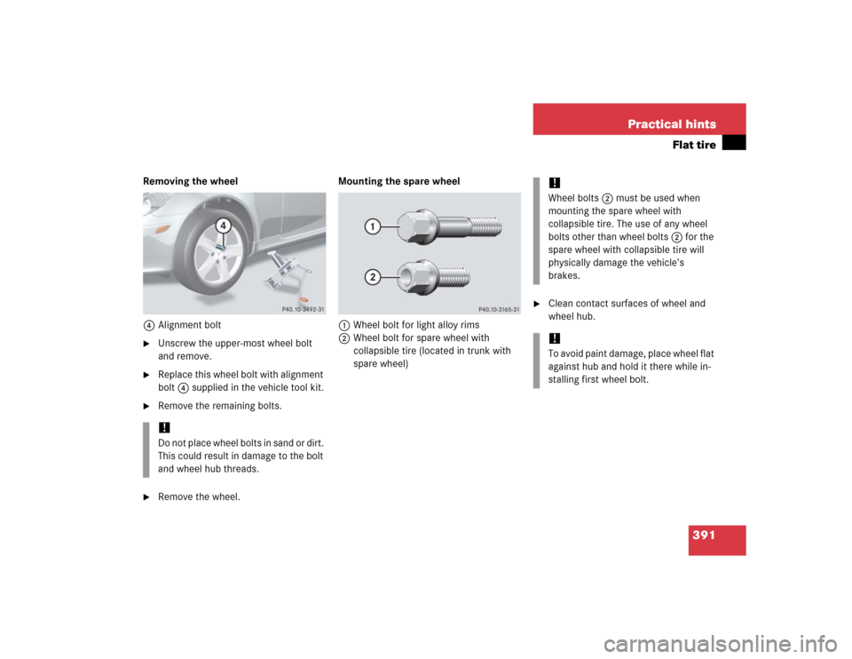
Removing the wheel
4Alignment bolt�
Unscrew the upper-most wheel bolt
and remove.
�
Replace this wheel bolt with alignment
bolt4 supplied in the vehicle tool kit.
�
Remove the remaining bolts.
�
Remove the wheel.Mounting the spare wheel
1Wheel bolt for light alloy rims
2Wheel bolt for spare wheel with
collapsible tire (located in trunk with
spare wheel)
�
Clean contact surfaces of wheel and
wheel hub.
!Do not place wheel bolts in sand or dirt.
This could result in damage to the bolt
and wheel hub threads.
!Wheel bolts2 must be used when
mounting the spare wheel with
collapsible tire. The use of any wheel
bolts other than wheel bolts2 for the
spare wheel with collapsible tire will
physically damage the vehicle’s
brakes. !To avoid paint damage, place wheel flat
against hub and hold it there while in-
stalling first wheel bolt.
Page 393 of 464
393 Practical hints
Flat tire
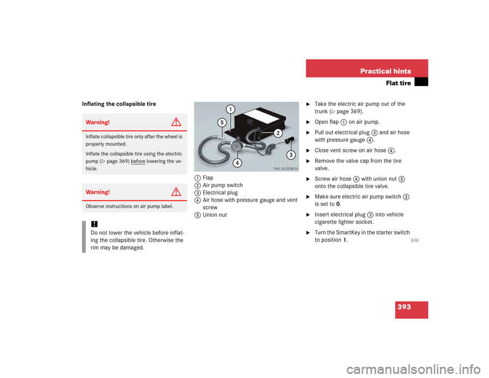
Inflating the collapsible tire
1Flap
2Air pump switch
3Electrical plug
4Air hose with pressure gauge and vent
screw
5Union nut
�
Take the electric air pump out of the
trunk (
�page 369).
�
Open flap1 on air pump.
�
Pull out electrical plug3 and air hose
with pressure gauge4.
�
Close vent screw on air hose4.
�
Remove the valve cap from the tire
valve.
�
Screw air hose4 with union nut5
onto the collapsible tire valve.
�
Make sure electric air pump switch2
is set to0.
�
Insert electrical plug3 into vehicle
cigarette lighter socket.
�
Turn the SmartKey in the starter switch
to position1.
Warning!
G
Inflate collapsible tire only after the wheel is
properly mounted.
Inflate the collapsible tire using the electric
pump (
�page 369) before
lowering the ve-
hicle.
Warning!
G
Observe instructions on air pump label.!Do not lower the vehicle before inflat-
ing the collapsible tire. Otherwise the
rim may be damaged.
��
Page 394 of 464

394 Practical hintsFlat tire�
PressI on electric air pump switch2.
The electric air pump switches on and
inflates the collapsible tire.
�
Inflate the collapsible tire to approxi-
mately 51 psi (3.5 bar).
This takes about five minutes for the
collapsible tire. Air hose4 and union
nut5 can become hot during infla-
tion. Exercise proper caution to avoid
burning yourself when using the equip-
ment.
�
Press0 on electric air pump switch2.
�
Turn the SmartKey in the starter switch
to position0.
The electric air pump should now be
switched off.
�
If the tire inflation pressure is above
51 psi (3.5 bar), release excess tire in-
flation pressure using the vent screw
on air hose4.
�
Detach the electric air pump.
�
Reinstall collapsible tire valve cap.
�
Store electrical plug3 and air
hose4 behind flap 1 and place the
electric air pump back in the trunk.
!Do not operate the electric air pump
longer than six minutes without inter-
ruption. Otherwise it may overheat.
You may operate the electric air pump
again after it has cooled off.
Warning!
G
Follow recommended tire inflation
pressures.
Do not underinflate tires. Underinflated tires
wear excessively and / or unevenly,
adversely affect handling and fuel economy,
and are more likely to fail from being over-
heated.
Do not overinflate tires. Overinflated tires
can adversely affect handling and ride
comfort, wear unevenly, increase stopping
distance, and result in sudden deflation
(blowout) because they are more likely to
become punctured or damaged by road
debris, potholes etc.
��
Page 395 of 464

395 Practical hints
Flat tire
Lowering the vehicle�
Lower vehicle by turning the crank
counterclockwise until vehicle is rest-
ing fully on its own weight.
�
Remove the jack.
1-5 Wheel bolts
�
Tighten the five wheel bolts evenly in
the direction of the arrow, following the
diagonal sequence illustrated
(1to5), until all bolts are tight.
Observe a tightening torque of
80 lb-ft (110 Nm).
�
Fully collapse the jack.
�
Place the vehicle tool kit, electric air
pump, and the jack back in the storage
compartment under the trunk floor.
�
Wrap the damaged wheel in the protec-
tive sheet provided with the spare
wheel and put the wheel in the trunk.
Warning!
G
Inflate the collapsible tire using the electric
pump (
�page 393) before
lowering the ve-
hicle.
Warning!
G
Have the tightening torque checked after
changing a wheel. The wheels could come
loose if they are not tightened to a torque of
80 lb-ft (110 Nm).iThe flat tire may be transported in the
trunk when the retractable hardtop is
closed.
Page 403 of 464
.
The")
403 Practical hints
Towing the vehicle
Installing towing eye bolt
The towing eye bolt is supplied with the ve-
hicle tool kit, located in the compartment
underneath the trunk floor (
�page 369).
The towing eyes are located on the passen-
ger side in the front and rear bumper.
�
Take vehicle tool kit out of trunk
(�page 369).1Cover in front bumper
2Cover in rear bumper
�
Press mark on corresponding cover1
or2 in direction of arrow for folding
down.
�
Lift cover off to reveal threaded hole for
towing eye bolt.
Do not remove cover completely.
�
Screw towing eye bolt in to its end stop
and tighten with lug wrench.
�
For removing towing eye bolt and rein-
stalling cover, follow the previously de-
scribed steps in reverse order.
iThe gear selector lever* will remain
locked in positionP (vehicles with au-
tomatic transmission*) and the Smart-
Key will not turn in the starter switch if
the battery is disconnected or dis-
charged. See notes on the battery
(�page 396) or on jump starting
(�page 399).
Vehicles with automatic transmission*:
For information on manual unlocking of
transmission selector lever, see
(�page 376).
iWhen closing the cover, insert the
latches first and gently press on the
opposite side until the cover fully en-
gages.
Make sure the cover’s check strap
does not get caught when closing.
Page 421 of 464
421 Technical data
Weights
�Weights
Model
SLK 350
SLK 55 AMG
Maximum roof load
110lb (50kg)
110 lb (50 kg)
Maximum trunk load
220 lb (100 kg)
220 lb (100 kg)
!This vehicle is not designed to carry
items on its roof. Roof rails and any
roof-mounted devices, unless express-
ly approved by Mercedes-Benz for use
on this vehicle model, must not be used
as they will damage the vehicle and
retractable hardtop.
At time of printing, Mercedes-Benz
does not offer any roof racks or any
other roof-mounted devices for use on
this vehicle.
!This vehicle is not designed to carry
any items on its trunk lid or accommo-
date any type of trunk lid rack or de-
vice. Using such devices may damage
the vehicle and retractable hardtop
mechanism.
Page 435 of 464

435 Technical terms
Power train
Collective term designating all compo-
nents used to generate and transmit
motive power to the drive axles, includ-
ing
�
Engine
�
Clutch/torque converter
�
Transmission
�
Transfer case
�
Drive shaft
�
Differential
�
Axle shafts/axles
Production options weight
(
�page 324)Program mode selector switch
Used to switch the automatic transmis-
sion between standard operation (S)
and comfort operation (C).
Vehicles with steering wheel gearshift
control and manual shift program: in
addition toS andC (for regularS
or comfortC operation, see above),
you can useM for manual shift pro-
gram.
PSI
(P
ounds per s
quare i
nch)
(
�page 324)
Recommended tire inflation pressure
(�page 324)REST
(Residual engine heat utilization)
Feature that uses the engine heat
stored in the coolant to heat the vehi-
cle interior for a short time after the en-
gine has been turned off.
Restraint systems
Seat belts, belt tensioners, air bags
and child restraint systems. As inde-
pendent systems, their protective func-
tions complement one another.
Rim
(
�page 324)
Retractable hardtop
Hardtop that can be opened and closed
at the push of a button and stored in
the trunk.
Page 444 of 464
 278
Tires (Traction) 278
Traveling abroad 281
Driving safety systems 80")
444 Index
Power assistance 273
Radio transmitters, control and
operation 281
Standing water 280
Tires 277
Tires (Speed rating) 278
Tires (Traction) 278
Traveling abroad 281
Driving safety systems 80
ABS 80
BAS 81
ESP 82
Driving systems
Cruise control 244
Driving the first
1000 miles/1500 km 272E
Easy-entry/exit feature (Seats) 99
Control system 142
Electric air pump 371
Electrical outlet 254
Electrical system
Technical data 419
Electronic Stability Program see ESP
Emergency call (911) 229
Emergency call system 257
GPS 258
Initiating an emergency call 259
Requirements 257
Tele Aid 258
Emergency operation
(Limp Home Mode) 166
Emergency operations
Locking driver’s door and trunk 375
Releasing trunk lid from inside 96
Remote door unlock 263
Retractable hardtop 377
Selector lever, unlocking
manually 376Unlocking the vehicle 374
Unlocking trunk 375
Unlocking vehicle 374
Emergency tensioning device see ETD
Emission control 282
Information label 410
Engine
Cleaning see Vehicle care
Compartment 287
Driving after replacement 272
Number (Label) 410
Number, description 432
Starting (Automatic transmission) 48
Starting (Manual transmission) 48
Technical data 412
Turning off with SmartKey 58
Engine oil 288, 424
Adding 292
Additives 424
Checking level (Control system) 289
Checking level (Dipstick) 291
Consumption 288
Display message 290
Viscosity 432