Page 35 of 416

35 Getting started
Unlocking
Starter switch positionsStarter switch0For removing SmartKey
The steering is locked when the
SmartKey is removed from the starter
switch. If necessary, move steering
wheel slightly to allow the locking
mechanism to engage.
1Power supply to some electrical con-
sumers, such as seat adjustment2Ignition (power supply for all electrical
consumers) and driving position.
All lamps (except high beam headlamp
indicator lamp and turn signal indicator
lamps unless activated) in the instru-
ment cluster come on. If a lamp in the
instrument cluster fails to come on
when the ignition is switched on, have
it checked and replaced if necessary. If
a lamp in the instrument cluster re-
mains on after starting the engine or
comes on while driving, refer to see
“Lamps in instrument cluster”
(
�page 288).
3Starting position
iWhen you switch on ignition, the indi-
cator and warning lamps (except high
beam headlamp indicator lamp and
turn signal indicator lamps unless acti-
vated) in the instrument cluster come
on. This indicates that the respective
system is operational. The indicator
and warning lamps (except high beam
headlamp indicator lamp and turn sig-
nal indicator lamps if activated) should
go out when the engine is running.iThe SmartKey can only be removed
from the starter switch with the gear
selector lever in positionP.
Page 37 of 416

37 Getting started
Adjusting
�Adjusting
SeatsWarning!
G
All seat, head restraint, steering wheel, and
rear view mirror adjustments, as well as fas-
tening of seat belts, must be done before
the vehicle is put into motion.Warning!
G
Do not adjust the driver’s seat while driving.
Adjusting the seat while driving could cause
the driver to lose control of the vehicle.
Never ride in a moving vehicle with the seat
back in an excessively reclined position as
this can be dangerous. You could slide un-
der the seat belt in a collision. If you slide
under it, the belt would apply force at the ab-
domen or neck. That could cause serious or
fatal injuries.
The seat back and seat belts provide the
best restraint when the wearer is in a nearly
upright position and belts are properly posi-
tioned on the body. Your seat must be ad-
justed so that you can correctly fasten your
seat belt (
�page 43).
Never place hands under the seat or near
any moving parts while a seat is being ad-
justed.
Warning!
G
When leaving the vehicle, always remove the
SmartKey from the starter switch, take it
with you, and lock the vehicle.
Even with the SmartKey removed from the
starter switch, the power seats can be oper-
ated when the respective door is open.
Therefore, do not leave children unattended
i n t h e v e h i c l e , o r w i t h a c c e s s t o a n u n l o c k e d
vehicle. Unsupervised use of vehicle equip-
ment may cause an accident and/or serious
personal injury.
Warning!
G
Children 12 years old and under must never
ride in the front seat, except in a
Mercedes-Benz authorized BabySmart
TM1
compatible child seat, which operates with
the BabySmart
TM system installed in the ve-
hicle to deactivate the passenger front
airbag when it is properly installed. Other-
wise they will be struck by the airbag when
it inflates in a crash. If this happens, serious
or fatal injury will result.
According to accident statistics, children
are safer when properly restrained in the
rear seating positions than in the front seat-
ing positions. Infants and small children
must ride in the back seats and be seated in
an appropriate infant or child restraint sys-
tem, which is properly secured with the ve-
hicle’s seat belt and top tether strap, or
secured via lower anchors and top tether
strap, fully in accordance with the child seat
manufacturer’s instructions.
1BabySmart
TM is a trademark of Siemens
Automotive Corp.
��
Page 38 of 416

38 Getting startedAdjustingSeat adjustment
The seat adjustment switches are located
in each front door.
1Head restraint height
2Seat backrest tilt
3Seat fore and aft adjustment
4Seat cushion tilt
5Seat height
�
Switch on the ignition (
�page 35).
or
�
Open the respective front door.
Seat fore and aft adjustment
�
Press the switch forward or back in the
direction of arrow3.
Adjust to a comfortable seating posi-
tion that still allows you to reach the
accelerator/brake pedal safely. The
position should be as far to the rear as
possible, consistent with ability to
properly operate controls.
A child’s risk of serious or fatal injuries is
significantly increased if the child restraints
are not properly secured in the vehicle and
the child is not properly secured in the child
restraint.
iWhen moving the seat, be sure that�
there are no items in the footwell or
behind the seats
�
the cup holder next to the armrest
is removed (
�page 192)
�
the cup holder in the front passen-
ger footwell is folded closed
(�page 192)
Otherwise you could damage the seats
and/or cup holders.
The memory function (
�page 107) lets
you store the setting for the seat posi-
tion together with the setting for the
steering wheel and the exterior rear
view mirrors.
��
Page 39 of 416

39 Getting started
Adjusting
Seat cushion tilt�
Press the switch up or down in the di-
rection of arrow4 until your upper
legs are lightly supported.
Seat backrest tilt
�
Press the switch forward or backward
in the direction of arrow2 until your
arms are slightly angled when holding
the steering wheel.
Seat height
�
Press the switch up or down in the di-
rection of arrow5.
Make sure you have sufficient head-
room.Head restraint height
�
Press the switch up or down in the di-
rection of arrow1.
Adjust head restraint to support the back
of the head approximately at eye level.Head restraint tilt
Manually adjust the angle of the head re-
straint.
�
Push or pull on the upper edge of the
head restraint cushion.
For more information, see “Seats”
(
�page 100).
Warning!
G
For your protection, drive only with properly
positioned head restraints.
Adjust head restraint so that the center of
the head restraint supports the back of the
head at eye level. This will reduce the poten-
tial for injury to the head and neck in the
event of an accident or similar situation.
Do not drive the vehicle without the seat
head restraints. Head restraints are intend-
ed to help reduce injuries during an acci-
dent.
Page 40 of 416
.
1Adjusting steering column, in or out
2Adjusting steering column, up or down
�
Switch on the ignitio")
40 Getting startedAdjustingSteering wheelThe lever is located on the steering column
(lower left).
1Adjusting steering column, in or out
2Adjusting steering column, up or down
�
Switch on the ignition (
�page 35).
or
�
Open the driver’s door.Adjusting steering column in or out
�
Move lever forward or back in the di-
rection of arrow1 until a comfortable
steering wheel position is reached with
your arms slightly bent at the elbow.
Adjusting steering column up or down
�
Move lever up or down in the direction
of arrow2.
Make sure your legs can move freely
and that all the displays (incl. malfunc-
tion and indicator lamps) on the instru-
ment cluster are clearly visible.
For more information, see “Heated steer-
ing wheel” (
�page 211).
Warning!
G
Do not adjust the steering wheel while driv-
ing. Adjusting the steering wheel while driv-
ing could cause the driver to lose control of
the vehicle.
When leaving the vehicle, always remove the
SmartKey from the starter switch, take it
with you, and lock the vehicle.
Even with the SmartKey removed from the
starter switch, the steering wheel adjust-
ment feature can be operated when the driv-
er’s door is open. Therefore, do not leave
children unattended in the vehicle, or with
access to an unlocked vehicle. Unsuper-
vised use of vehicle equipment may cause
an accident and/or serious personal injury.
iThe memory function (
�page 107) lets
you store the setting for the steering
wheel together with the setting for the
seat position and the exterior rear view
mirrors.
Page 42 of 416

42 Getting startedAdjustingThe buttons are located above the exterior
lamp switch.
1Adjustment button
2Driver’s side exterior rear view mirror
3Passenger-side exterior rear view
mirror
�
Switch on the ignition (
�page 35).
�
Press switch2 or3 to select the
respective exterior rear view mirror.
�
Push adjustment button1 up, down,
left, or right according to the desired
setting.
For more information, see “Storing exterior
rear view mirror parking position”
(
�page 109).
!If an exterior rear view mirror housing
is forcibly pushed forward (hit from the
rear) or rearward (hit from the front),
reposition it by applying firm pressure
until it snaps into place. The exterior
rear view mirror housing is now proper-
ly positioned and you can adjust the
mirror normally.
iAt low ambient temperatures, the exte-
rior rear view mirrors will be heated au-
tomatically.iThe memory function (
�page 107) lets
you store the setting for the exterior
rear view mirrors together with the set-
tings for the steering wheel and the
seat position.
Page 51 of 416

51 Getting started
Driving
After a cold start, the automatic transmis-
sion shifts at a higher revolution. This al-
lows the catalytic converter to reach its
operating temperature earlier.
For more information, see “Driving instruc-
tions” (
�page 216).
For information on off-road driving, see
“Off-road driving” (
�page 223).
Switching on headlamps
Low beam headlamps
The exterior lamp switch is located on the
dashboard to the left of the steering wheel.Exterior lamp switch1Off
2Low beam headlamps on�
Turn exterior lamp switch to
positionB.
!Do not run cold engine at high engine
speeds. Running a a cold engine at high
engine speeds may shorten the service
life of the engine.iYou can open the doors from inside at
any time. Open doors only when the
conditions are safe to do so.
You can deactivate the automatic
locking using the control system
(�page 141).
!Simultaneously depressing the acceler-
ator pedal and applying the brake re-
duces engine performance and causes
premature brake and drivetrain wear.
Warning!
G
On slippery road surfaces, never downshift
in order to obtain braking action. This could
result in drive wheel slip and reduced vehi-
cle control. Your vehicle’s ABS will not pre-
vent this type of loss of control.
Page 52 of 416
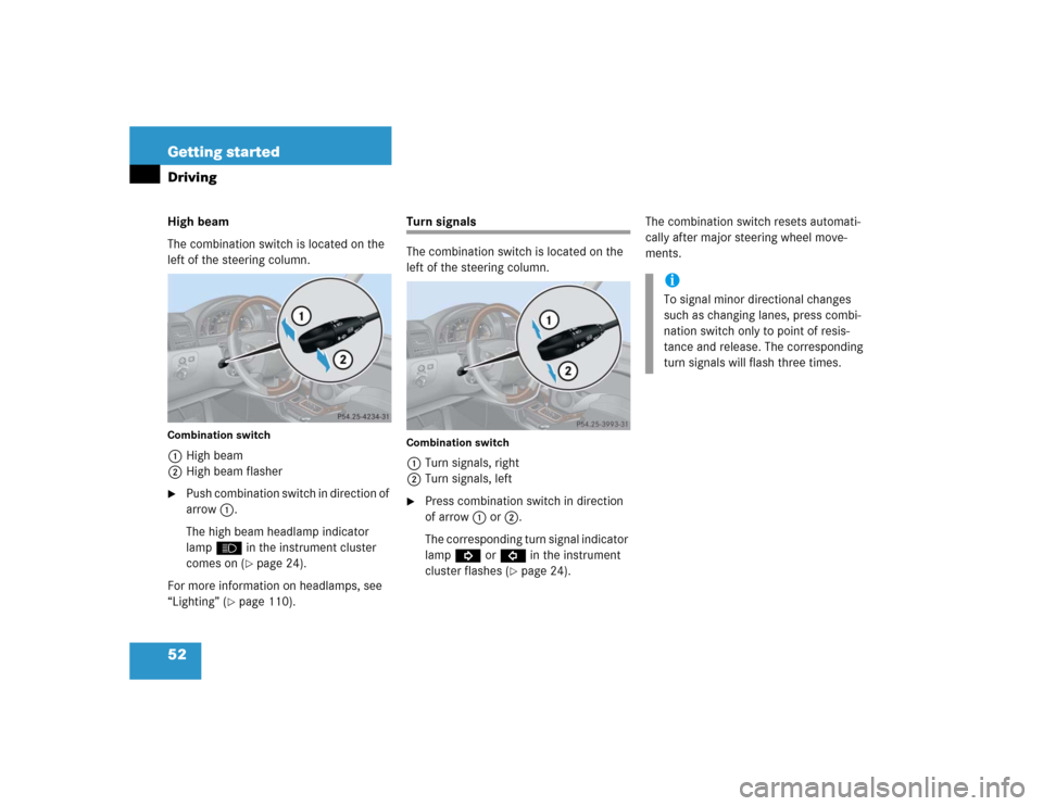
52 Getting startedDrivingHigh beam
The combination switch is located on the
left of the steering column.Combination switch1High beam
2High beam flasher�
Push combination switch in direction of
arrow1.
The high beam headlamp indicator
lampA in the instrument cluster
comes on (
�page 24).
For more information on headlamps, see
“Lighting” (
�page 110).
Turn signals
The combination switch is located on the
left of the steering column.Combination switch1Turn signals, right
2Turn signals, left�
Press combination switch in direction
of arrow1 or2.
The corresponding turn signal indicator
lampK orL in the instrument
cluster flashes (
�page 24).The combination switch resets automati-
cally after major steering wheel move-
ments.
iTo signal minor directional changes
such as changing lanes, press combi-
nation switch only to point of resis-
tance and release. The corresponding
turn signals will flash three times.