Page 294 of 474

293
Operation
Engine compartment
Checking engine oil level with the
control system
When checking the oil level�
the vehicle must be parked on level
ground.
�
with the engine at operating tempera-
ture, the vehicle must have been
stationary for at least five minutes with
the engine turned off.
�
with the engine not at operating tem-
perature yet, the vehicle must have
been stationary for at least 30 minutes
with the engine turned off.
To check the engine oil level via the
multifunction display, do the following:
�
Switch on the ignition (
�page 33).
The standard display (
�page 123) should
appear in the multifunction display.
�
Press button k orj on the
steering wheel until the following
message is seen in the multifunction
display: One of the following messages will
subsequently appear in the indicator:
�
Engine oil level
OK
�
Add 1.0 qt engine oil
for max. oil level(Canada:
1.0 l
)
�
Add 1.5 qts engine oil
for max. oil level(Canada:
1.5 l
)
�
Add 2.0 qts engine oil
for max. oil level(Canada:
2.0 l
)
�
If necessary, add engine oil.
For adding engine oil, see (
�page 294).
For more information on engine oil, see
“Technical data” section (
�page 426) and
(
�page 428).
Other display messages
If the SmartKey is not turned to position 2
in the starter switch, the following
message will appear:
Switch ignition on to
check engine oil level�
Switch on the ignition (
�page 33).
iIf you want to interrupt the checking
procedure, press the k orj
button on the multifunction steering
wheel.
Page 305 of 474
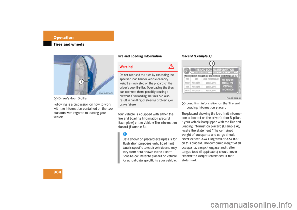
304 OperationTires and wheels1Driver’s door B-pillar
Following is a discussion on how to work
with the information contained on the two
placards with regards to loading your
vehicle. Tire and Loading Information
Your vehicle is equipped with either the
Tire and Loading Information placard
(Example A) or the Vehicle Tire Information
placard (Example B). Placard (Example A)
1 Load limit information on the Tire and
Loading Information placard
The placard showing the load limit informa-
tion is located on the driver’s door B-pillar.
If your vehicle is equipped with the Tire and
Loading Information placard (Example A),
locate the statement “The combined
weight of occupants and cargo should
never exceed XXX kilograms or XXX lbs.”
on this placard. The combined weight of all
occupants, cargo / luggage and trailer
tongue load (if applicable) should never
exceed the weight referenced in that
statement.
Warning!
G
Do not overload the tires by exceeding the
specified load limit or vehicle capacity
weight as indicated on the placard on the
driver’s door B-pillar. Overloading the tires
can overheat them, possibly causing a
blowout. Overloading the tires can also
result in handling or steering problems, or
brake failure.iData shown on placard examples is for
illustration purposes only. Load limit
data is specific to each vehicle and may
vary from data shown in the illustra-
tions below. Refer to placard on vehicle
for actual data specific to your vehicle.
Page 316 of 474
315
Operation
Tires and wheels
Rim diameter
The rim diameter
4 (
�page 314) is the
diameter of the bead seat, not the
diameter of the rim edge. Rim diameter is
indicated in inches (in).
Tire load rating
The tire load rating 5 (�page 314) is a
numerical code associated with the
maximum load a tire can support.
For example, a load rating of 91 corre-
sponds to a maximum load of 1 356 lbs
(615 kg) the tire is designed to support.
See also “Maximum tire load”
(
�page 319) where the maximum load as-
sociated with the load index is indicated in
kilograms and lbs. For additional information on tire load
rating, see “Load identification”
(
�page 317).
Warning
G
The tire load rating must always be at least
half of the GAWR (
�page 323) of your vehi-
cle. Otherwise, tire failure may be the result
which may cause an accident and/or seri-
ous personal injury to you or others.
Always replace rims and tires with the same
designation, manufacturer and type as
shown on the original part.
Warning!
G
Do not overload the tires by exceeding the
specified load limit or vehicle capacity
weight as indicated on the placard located
on the driver's door B-pillar. Overloading the
tires can overheat them, possibly causing a
blowout. Overloading the tires can also
result in handling or steering problems, or
brake failure.
iTire load rating 5 (
�page 314) and
tire speed rating 6 (�page 314) are
also referred to as “service descrip-
tion”.
Page 320 of 474
319
Operation
Tires and wheels
Tire type code
The code
4 (
�page 318) may, at the
option of the manufacturer, be used as a
descriptive code for identifying significant
characteristics of the tire.
Date of manufacture
The date of manufacture 5 (
�page 318)
identifies the week and year of manufac-
ture.
The first two figures identify the week,
starting with “01” to represent the first full
week of the calendar year. The second two
figures represent the year.
For example, “3202” represents the 32nd
week of 2002.
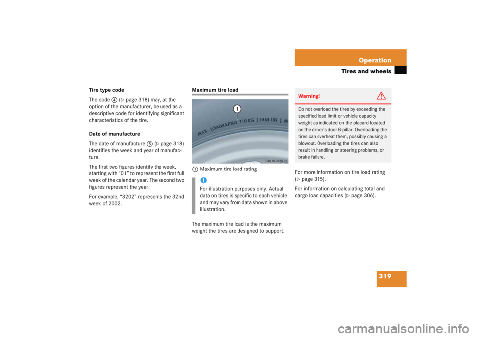
Maximum tire load
1 Maximum tire load rating
The maximum tire load is the maximum
weight the tires are designed to support. For more information on tire load rating
(
�page 315).
For information on calculating total and
cargo load capacities (
�page 306).
iFor illustration purposes only. Actual
data on tires is specific to each vehicle
and may vary from data shown in above
illustration.
Warning!
G
Do not overload the tires by exceeding the
specified load limit or vehicle capacity
weight as indicated on the placard located
on the driver’s door B-pillar. Overloading the
tires can overheat them, possibly causing a
blowout. Overloading the tires can also
result in handling or steering problems, or
brake failure.
Page 324 of 474
323
Operation
Tires and wheels
Tire and loading terminology
Accessory weight
The combined weight (in excess of those
standard items which may be replaced) of
automatic transmission, power steering,
power brakes, power windows, power
seats, radio, and heater, to the extent that
these items are available as
factory-installed equipment (whether
installed or not).
Air pressure
The amount of air inside the tire pressing
outward on each square inch of the tire.
Air pressure is expressed in pounds per
square inch (psi), or kilopascal (kPa) or
bars.
Aspect ratio
Dimensional relationship between tire
section height and section width
expressed in percentage.
Bar
Another metric unit for air pressure. There
are 14.5038 pounds per square inch (psi)
to 1 bar; there are 100 kilopascals (kPa)
to 1 bar.
Bead
The tire bead contains steel wires wrapped
by steel cords that hold the tire onto the
rim.
Cold tire inflation pressure
Tire inflation pressure when your vehicle
has been sitting for at least three hours or
driven no more than one mile (1.6 km). Curb weight
The weight of a motor vehicle with
standard equipment including the maxi-
mum capacity of fuel, oil, and coolant, and,
if so equipped, air conditioning and
additional optional equi
pment, but without
passengers and cargo.
DOT (D
epartment o
f T
ransportation)
A tire branding symbol which denotes the
tire meets requirements of the
U.S. Department of Transportation.
GAWR (G
ross A
xle W
eight R
ating)
The GAWR is the maximum permissible
axle weight. The gross vehicle weight on
each axle must never exceed the GAWR for
the front and rear axle indicated on the
Certification label located on the driver's
door B-pillar.
Page 332 of 474
331
Operation
Maintenance
Clearing the maintenance service indicator
The maintenance service indicator is
automatically cleared�
after ten seconds when you switch on
the ignition or when reaching the main-
tenance service threshold while driving
�
after 30 seconds, once the suggested
maintenance service term has passed
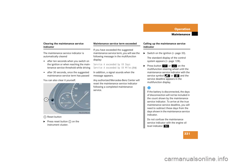
You can also clear it yourself.
1 Reset button
�
Press reset button 1 on the
instrument cluster.
Maintenance service term exceeded
If you have exceeded the suggested
maintenance service term, you will see the
following message in the multifunction
display:Service A exceeded by XX Days
Service A exceeded by XX Miles
(Km)
In addition, a signal sounds when the
message appears.
Any authorized Mercedes-Benz Center will
reset the maintenance service indicator
following a completed maintenance
service. Calling up the maintenance service
indicator�
Switch on the ignition (
�page 33).
The standard display of the control
system appears (
�page 128).
�
Press button k orj on the
multifunction steering wheel until the
maintenance service indicator with the
service symbol 9 or´ and the
service deadline appears in the
multifunction display.iIf the battery is disconnected, the days
of disconnection will not be included in
the count shown by the maintenance
service indicator. To arrive at the true
maintenance service deadline, you will
need to subtract these days from the
days shown in the maintenance service
indicator.
Do not confuse the maintenance
service indicator with the engine oil
level indicator :.
Page 338 of 474
337
Operation
Vehicle care
Instrument cluster
Use a gentle dishwashing detergent or
mild detergent for delicate fabrics as a
washing solution. Wipe with a cloth moist-
ened in lukewarm solution. Do not use
scouring agents.
Steering wheel and gear selector lever
Wipe with a damp cloth and dry thoroughly
or clean with Mercedes-Benz approved
Leather Care.
Cup holders
Use a gentle dishwashing detergent or
mild detergent for delicate fabrics as a
washing solution. Wipe with a cloth moist-
ened in lukewarm solution. Do not use
scouring agents.
Hard plastic trim items
Pour Mercedes-Benz approved Interior
Care onto soft lint-free cloth and apply
with light pressure. Headliner
Clean with soft bristle brush, or use a
dry-shampoo cleaner in case of excessive
dirt.
Seat belts
The webbing must not be treated with
chemical cleaning agents. Use only clear,
lukewarm water and soap. Do not dry the
webbing at temperatures above 176°F
(80°C) or in direct sunlight.
Warning!
G
Do not bleach or dye seat belts as this may
severely weaken them. In a crash they may
not be able to provide adequate protection.
Page 341 of 474

340 Practical hintsWhat to do if …Lamps in instrument clusterGeneral information:
If any of the following lamps in the instru-
ment cluster fails to come on during thebulb self-check when switching on the
ignition, have the respective bulb checked
and replaced if necessary.Problem
Possible cause
Suggested solution
-
The yellow ABS malfunction
indicator lamp comes on while
driving.
The ABS has detected a malfunction and has
switched off. The BAS and the ESP are also
switched off (see messages in display).
The brake system is still functioning normally
but without the ABS available.
If the ABS control unit is malfunctioning,
other systems such as the navigation
system* or the automatic transmission* may
also be malfunctioning.
�
Continue driving with added caution.
Wheels may lock during hard braking,
reducing steering capability.
�
Read and observe messages in the
display (
�page 353).
�
Have the system checked at an autho-
rized Mercedes-Benz Center as soon
as possible.
Failure to follow these instructions
increases the risk of an accident.
The charging voltage has fallen below ten
volts. The ABS has switched off.
The battery might not be charged sufficiently.
�
Switch off electrical consumers that
are currently not needed, e.g. seat
heating*.
�
If necessary, have the generator
(alternator) and battery checked.
When the voltage is above this value
again, the ABS is operational again.