Page 137 of 205

WARNING:Inexper t modifications or additions to the electrical
system could jeopardise safety.
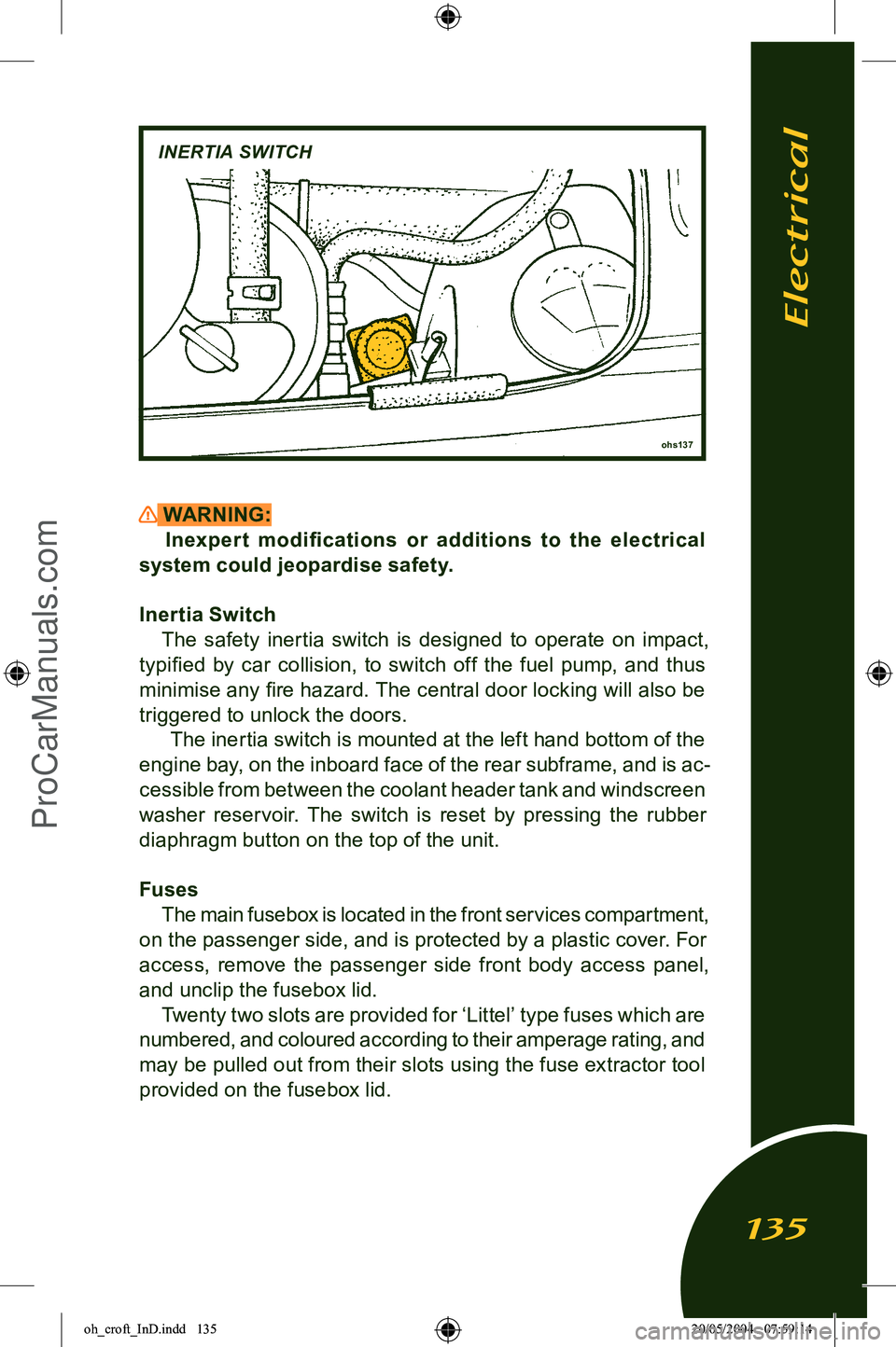
Inertia Switch The safety inertia switch is designed to operate on impact,
typified by car collision, to switch off the fuel pump, and thus
minimise any fire hazard. The central door locking will also be
triggered to unlock the doors. The inertia switch is mounted at the left hand bottom of the
engine bay, on the inboard face of the rear subframe, and is ac
-
cessible from between the coolant header tank and windscreen
washer reservoir. The switch is reset by pressing the rubber
diaphragm button on the top of the unit.
Fuses The main fusebox is located in the front services compartment,
on the passenger side, and is protected by a plastic cover. For
access, remove the passenger side front body access panel,
and unclip the fusebox lid. Twenty two slots are provided for ‘Littel’ type fuses which are
numbered, and coloured according to their amperage rating, and
may be pulled out from their slots using the fuse extractor tool provided on the fusebox lid.
ohs137
INERTIA SWITCH
Electrical
135
oh_croft_InD.indd 13520/05/2004 07:59:14ProCarManuals.com
Page 142 of 205

3. If adjustment is required, the clear cover and mask must be removed from the body. From within the wheelarch, remove
the access panel from the wheelarch liner to expose the
headlamp cover retaining screws. Use the hexagonal key provided in the toolkit (in the rear pocket on the batter y
cover) to release the three socket head retaining screws and washers, and withdraw the cover assembly complete
with rubber edge seal from the body. When refitting, do not overtighten the fixings.
4. To adjust the low beam laterally, adjust the dome headed screw at the upper inboard side of the low beam (uppermost)
lamp, accessed from the front of the lamp. Turn clockwise to
adjust the beam to the right. Optimum setting is 0%. To adjust
the vertical aim of the low beam, adjust the dome headed screw at the lower outboard side of the lamp, accessed
from the front of the lamp. Turn clockwise to raise the beam.
Optimum setting is -1.5%.
5. Repeat for the RH lamp. 6. Centralise the machine on the LH high beam (lowermost) lamp, and switch on the high beams. Check the high beam
alignment which should be centralised with the marker dot on
the machine screen or slightly below the horizontal. Optimum
setting is 0%.
ohs105a
HEADLAMP COVER UNIT SOCKET BOLTS
Electrical
140
oh_croft_InD.indd 14020/05/2004 07:59:16ProCarManuals.com
Page 143 of 205
- To adjust the high beam laterally, adjust the dome headed screw at the upper inboard side of the lamp, accessed from behind the lamp. Turn clockwise to adjust the beam to the
right.
- To adjust the vertical aim of the high beam, adjust the dome headed screw at the lower outboard side of the lamp, ac
-
cessed from behind the lamp. Turn clockwise to raise the
beam.
7. Repeat for the RH lamp. 8. Re-fit the cover/mask assemblies complete with edge seal to the body, and secure with the three socket head screws and
washers. Refit the wheelarch access panel.
m257
Vertical adjuster
Lateral adjuster Lateral adjuster
High beam lamp
Vertical adjuster
Low beam lamp
Electrical
141
oh_croft_InD.indd 14120/05/2004 07:59:16ProCarManuals.com
Page 154 of 205

Storing Your EliseIf you intend to store your Elise for a prolonged period, con
-
sult your Lotus dealer who will be pleased to advise you. We recommend that the car is stored inside a secure garage. The
following guidelines are provided for your information:
• Ensure the engine oil and filter, coolant and brake fluid have recently been renewed. The a.c. system should be in good
working order and fully charged.
• Thoroughly clean the inside and outside of the car, including the engine compartment. If necessary, use a ‘jet’ washer to remove dirt and salt deposits from the underside, but do not
use around bearings, hydraulic components, painted surfaces or the soft top roof. Allow to dry completely.
• Chock the road wheels, leave off the parking brake, and engage reverse gear.
• Increase the tire pressures to 60 psi (4 bar). If possible, move the car slightly every month to help avoid flat spots on the
Tires.
• Either leave the battery in the car and connect a battery management (conditioner) type of charger, or remove the battery and trickle charge every two months. Note that with
the battery disconnected or removed, the alarm system is
de-activated.
• Unless the garage is equipped with a de-humidifier, the use of drying agents (Silica-Gel) is recommended in cars with
leather upholstery and in conditions of high humidity.
• The use of unapproved car covers may have a detrimental effect on the car’s paint finish and such damage will not be
covered by your car’s warranty.
In general, the Elise will be kept in best operating condition
by regular use.
Accessories
152
oh_croft_InD.indd 15220/05/2004 07:59:19ProCarManuals.com
Page 192 of 205

Steering Lock ........................................................................44
Storing Your Elise ................................................................ 152
Sun Visors .............................................................................. 41
Tachometer ............................................................................. 51
Technical Data ..................................................................... 155
Tell Tale Lamps ...................................................................... 46
Tie Down, car securing ......................................................... 147
Towing Eye ........................................................................... 146
Trip Re corder ......................................................................... 53
Turn Indicators Switch ........................................................... 58
Tires ...................................................................................... 115
Tire Inflator Aerosol .............................................................. 124
Tire Chains ........................................................................... 120
Identification, car ................................................................... 15
Warning ‘Tell Tale ’ Lamps ..................................................... 46
Warranty ............................................................................... 161
Washer Reservoir ................................................................ 109
Washing, bodycare ................................................................ 93
Wheelbolts ........................................................................... 126
Wheels ................................................................................ 126
Windows, door ...................................................................... 42
Windscreen Wiper/ Washer Control ...................................... 59
Wiper Blade ......................................................................... 109
Index
190
oh_croft_InD.indd 19020/05/2004 07:59:26ProCarManuals.com