Page 490 of 969
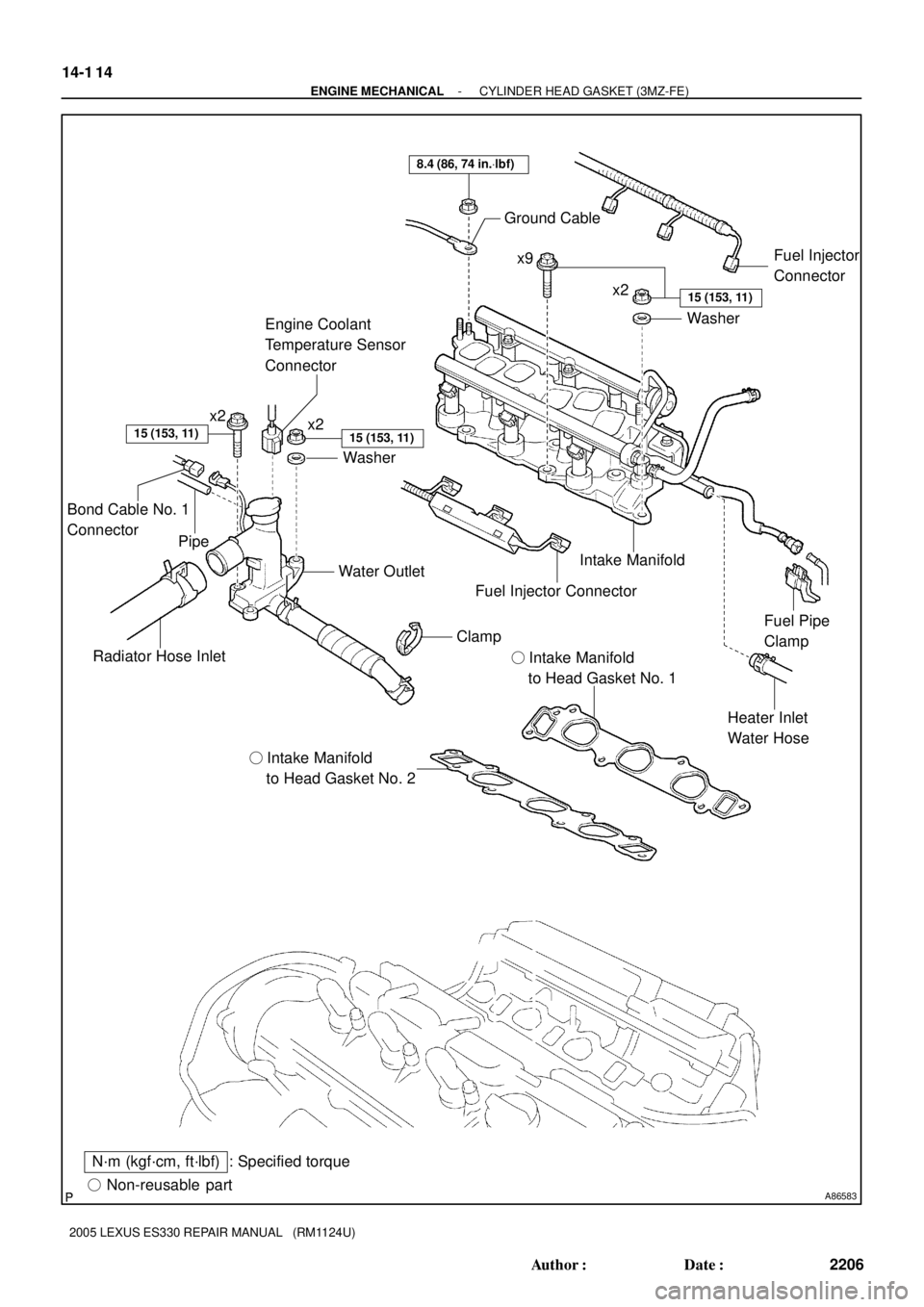
A86583� Non-reusable part
: Specified torqueN´m (kgf´cm, ft´lbf)� Intake Manifold
to Head Gasket No. 2� Intake Manifold
to Head Gasket No. 1
Radiator Hose InletWater Outlet
Heater Inlet
Water Hose Intake Manifold Ground Cable
Washer
8.4 (86, 74 in.Vlbf)
x2x9
x2
Washer
15 (153, 11)
15 (153, 11)
Fuel Pipe
Clamp
15 (153, 11)
Fuel Injector
Connector
Clamp
Fuel Injector Connector
x2
Engine Coolant
Temperature Sensor
Connector
Bond Cable No. 1
Connector
Pipe
14-1 14
- ENGINE MECHANICALCYLINDER HEAD GASKET (3MZ-FE)
2206 Author�: Date�:
2005 LEXUS ES330 REPAIR MANUAL (RM1124U)
Page 503 of 969
A86583� Non-reusable part
: Specified torqueN´m (kgf´cm, ft´lbf)� Intake Manifold
to Head Gasket No. 2� Intake Manifold
to Head Gasket No. 1
Radiator Hose InletWater Outlet
Heater Inlet
Water Hose Intake Manifold Ground Cable
Washer
8.4 (86, 74 in.Vlbf)
x2x9
x2
Washer
15 (153, 11)
15 (153, 11)
Fuel Pipe
Clamp
15 (153, 11)
Fuel Injector
Connector
Clamp
Fuel Injector Connector
x2
Engine Coolant
Temperature Sensor
Connector
Bond Cable No. 1
Connector
Pipe
- ENGINE MECHANICALCYLINDER HEAD GASKET NO.2 (3MZ-FE)
14-127
2219 Author�: Date�:
2005 LEXUS ES330 REPAIR MANUAL (RM1124U)
Page 510 of 969
A86575
A78718
Front
A78719
Front
1
23
8
7
6
5
4
A79822
Front 14-134
- ENGINE MECHANICALCYLINDER HEAD GASKET NO.2 (3MZ-FE)
2226 Author�: Date�:
2005 LEXUS ES330 REPAIR MANUAL (RM1124U)
34. REMOVE WATER INLET PIPE (See page 16-16)
35. REMOVE IGNITION COIL ASSY
36. REMOVE CYLINDER HEAD COVER SUB-ASSY LH (See page 14-7)
37. REMOVE NO.3 CAMSHAFT SUB-ASSY (See page 14-107)
38. REMOVE NO.4 CAMSHAFT SUB-ASSY (See page 14-107)
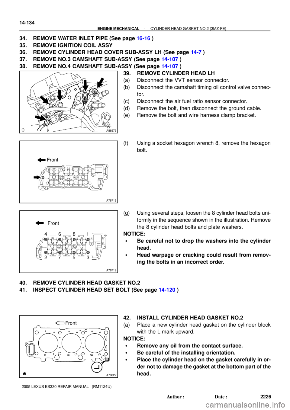
39. REMOVE CYLINDER HEAD LH
(a) Disconnect the VVT sensor connector.
(b) Disconnect the camshaft timing oil control valve connec-
tor.
(c) Disconnect the air fuel ratio sensor connector.
(d) Remove the bolt, then disconnect the ground cable.
(e) Remove the bolt and wire harness clamp bracket.
(f) Using a socket hexagon wrench 8, remove the hexagon
bolt.
(g) Using several steps, loosen the 8 cylinder head bolts uni-
formly in the sequence shown in the illustration. Remove
the 8 cylinder head bolts and plate washers.
NOTICE:
�Be careful not to drop the washers into the cylinder
head.
�Head warpage or cracking could result from remov-
ing the bolts in an incorrect order.
40. REMOVE CYLINDER HEAD GASKET NO.2
41. INSPECT CYLINDER HEAD SET BOLT (See page 14-120)
42. INSTALL CYLINDER HEAD GASKET NO.2
(a) Place a new cylinder head gasket on the cylinder block
with the L mark upward.
NOTICE:
�Remove any oil from the contact surface.
�Be careful of the installing orientation.
�Place the cylinder head on the gasket carefully in or-
der not to damage the gasket at the bottom part of the
head.
Page 511 of 969
A78719
1
2
3
4
5
67
8
Front
A78730
90�
Front
Painted Mark
A78718
Front
- ENGINE MECHANICALCYLINDER HEAD GASKET NO.2 (3MZ-FE)
14-135
2227 Author�: Date�:
2005 LEXUS ES330 REPAIR MANUAL (RM1124U)
43. INSTALL CYLINDER HEAD LH
NOTICE:
The cylinder head bolts are tightened in 2 successive
steps.
(a) Apply a light coat of engine oil to the threads of the cylin-
der head bolts.
(b) Install the plate washer to the cylinder head bolt.
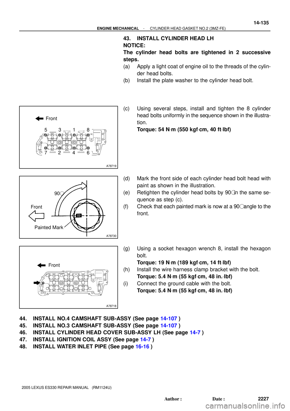
(c) Using several steps, install and tighten the 8 cylinder
head bolts uniformly in the sequence shown in the illustra-
tion.
Torque: 54 NVm (550 kgfVcm, 40 ftVlbf)
(d) Mark the front side of each cylinder head bolt head with
paint as shown in the illustration.
(e) Retighten the cylinder head bolts by 90�in the same se-
quence as step (c).
(f) Check that each painted mark is now at a 90� angle to the
front.
(g) Using a socket hexagon wrench 8, install the hexagon
bolt.
Torque: 19 NVm (189 kgfVcm, 14 ftVlbf)
(h) Install the wire harness clamp bracket with the bolt.
Torque: 5.4 NVm (55 kgfVcm, 48 in.Vlbf)
(i) Connect the ground cable with the bolt.
Torque: 5.4 NVm (55 kgfVcm, 48 in.Vlbf)
44. INSTALL NO.4 CAMSHAFT SUB-ASSY (See page 14-107)
45. INSTALL NO.3 CAMSHAFT SUB-ASSY (See page 14-107)
46. INSTALL CYLINDER HEAD COVER SUB-ASSY LH (See page 14-7)
47. INSTALL IGNITION COIL ASSY (See page 14-7)
48. INSTALL WATER INLET PIPE (See page 16-16)
Page 572 of 969
A86261� Non-reusable part
: Specified torqueN´m (kgf´cm, ft´lbf)Knock Sensor
Knock Sensor Connector
20 (204, 14)
� Intake Manifold
to Head Gasket No. 2� Intake Manifold
to Head Gasket No. 1
Radiator Hose InletWater Outlet
Heater Inlet
Water Hose Intake Manifold Ground Cable
Washer
8.4 (86, 74 in.Vlbf)
x2x9
x2
Washer
15 (153, 11)
15 (153, 11)
Fuel Pipe
Clamp
Engine Moving
Control Rod
23 (235, 17)
15 (153, 11)
x2
Fuel Injector
Connector
Clamp
Fuel Injector Connector
64 (653, 47)
x2
Engine Coolant
Temperature Sensor
Connector
Radio Setting
Condenser
64 (653, 47)
Bond Cable No. 1
Connector
Pipe
- ENGINE CONTROL SYSTEMKNOCK SENSOR (3MZ-FE)
10-15
2020 Author�: Date�:
2005 LEXUS ES330 REPAIR MANUAL (RM1124U)
Page 574 of 969
A86265
(c)
(d)
(d)
(d)
(d)
(d)(d)
A862661 2
3 4
75
68
9 10
11
A86267
(a)
(b)
(c)
- ENGINE CONTROL SYSTEMKNOCK SENSOR (3MZ-FE)
10-17
2022 Author�: Date�:
2005 LEXUS ES330 REPAIR MANUAL (RM1124U)
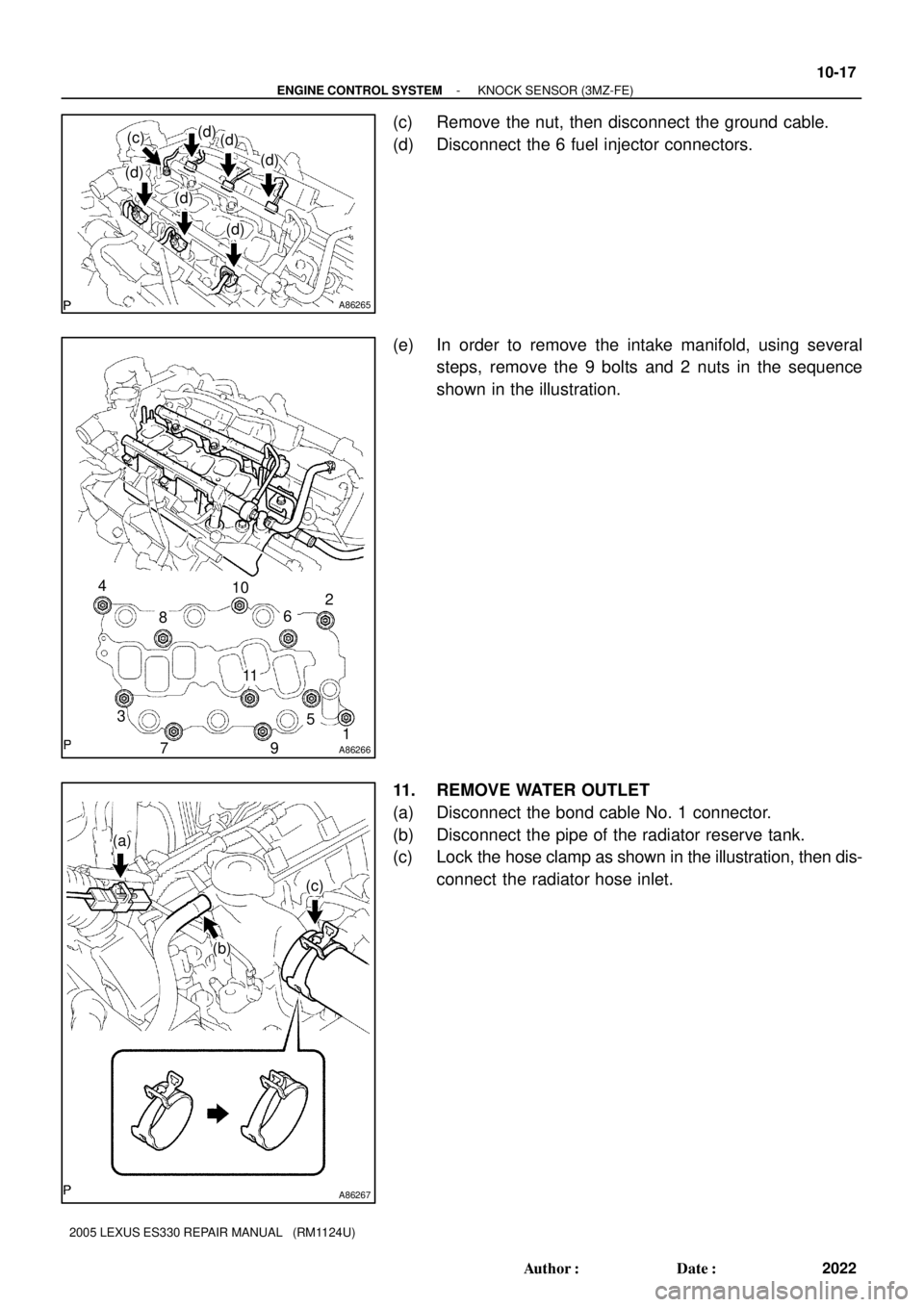
(c) Remove the nut, then disconnect the ground cable.
(d) Disconnect the 6 fuel injector connectors.
(e) In order to remove the intake manifold, using several
steps, remove the 9 bolts and 2 nuts in the sequence
shown in the illustration.
11. REMOVE WATER OUTLET
(a) Disconnect the bond cable No. 1 connector.
(b) Disconnect the pipe of the radiator reserve tank.
(c) Lock the hose clamp as shown in the illustration, then dis-
connect the radiator hose inlet.
Page 576 of 969
A8626611 10
9 8
5
7
64
3 2
1
A86269
Push
Fuel Pipe
Clamp
A86262
A
B
B
B
- ENGINE CONTROL SYSTEMKNOCK SENSOR (3MZ-FE)
10-19
2024 Author�: Date�:
2005 LEXUS ES330 REPAIR MANUAL (RM1124U)
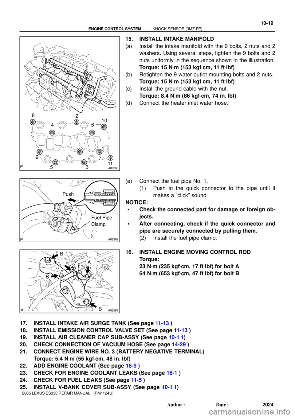
15. INSTALL INTAKE MANIFOLD
(a) Install the intake manifold with the 9 bolts, 2 nuts and 2
washers. Using several steps, tighten the 9 bolts and 2
nuts uniformly in the sequence shown in the illustration.
Torque: 15 NVm (153 kgfVcm, 11 ftVlbf)
(b) Retighten the 9 water outlet mounting bolts and 2 nuts.
Torque: 15 NVm (153 kgfVcm, 11 ftVlbf)
(c) Install the ground cable with the nut.
Torque: 8.4 NVm (86 kgfVcm, 74 in.Vlbf)
(d) Connect the heater inlet water hose.
(e) Connect the fuel pipe No. 1.
(1) Push in the quick connector to the pipe until it
makes a ºclickº sound.
NOTICE:
�Check the connected part for damage or foreign ob-
jects.
�After connecting, check if the quick connector and
pipe are securely connected by pulling them.
(2) Install the fuel pipe clamp.
16. INSTALL ENGINE MOVING CONTROL ROD
Torque:
23 NVm (235 kgfVcm, 17 ftVlbf) for bolt A
64 NVm (653 kgfVcm, 47 ftVlbf) for bolt B
17. INSTALL INTAKE AIR SURGE TANK (See page 11-13)
18. INSTALL EMISSION CONTROL VALVE SET (See page 11-13)
19. INSTALL AIR CLEANER CAP SUB-ASSY (See page 10-1 1)
20. CHECK CONNECTION OF VACUUM HOSE (See page 14-29)
21. CONNECT ENGINE WIRE NO. 3 (BATTERY NEGATIVE TERMINAL)
Torque: 5.4 NVm (55 kgfVcm, 48 in.Vlbf)
22. ADD ENGINE COOLANT (See page 16-9)
23. CHECK FOR ENGINE COOLANT LEAKS (See page 16-1)
24. CHECK FOR FUEL LEAKS (See page 11-5)
25. INSTALL V-BANK COVER SUB-ASSY (See page 10-1 1)