Page 2892 of 3419
TROUBLE DIAGNOSIS FOR SELF-DIAGNOSTIC ITEMS
RSU-17
C
D
F
G
H
I
J
K
L
MA
B
RSU
Revision: October 20052005 QX56
TROUBLE DIAGNOSIS FOR SELF-DIAGNOSTIC ITEMSPFP:00000
Height Sensor System InspectionEES001HA
INSPECTION PROCEDURE
1. SELF-DIAGNOSIS RESULT CHECK
Check self-diagnosis results.
Is the above displayed in the self-diagnosis display items?
YES >> GO TO 3.
NO >> GO TO 2.
2. DATA MONITOR CHECK
Conduct data monitor of "HEIGT SEN" to check if the status is normal.
OK or NG
OK >> Inspection End.
NG >> GO TO 3.
3. CONNECTOR INSPECTION
1. Turn ignition switch OFF.
2. Disconnect suspension control unit connector B3 and height sensor C8.
3. Check the terminals for deformation, disconnection, looseness or damage.
OK or NG
OK >> GO TO 4.
NG >> Repair or replace as necessary.
Self-diagnosis results
C1801
C1806
C1807
HEIGT SEN 0.2V - 4.8V
Page 2894 of 3419
TROUBLE DIAGNOSIS FOR SELF-DIAGNOSTIC ITEMS
RSU-19
C
D
F
G
H
I
J
K
L
MA
B
RSU
Revision: October 20052005 QX56
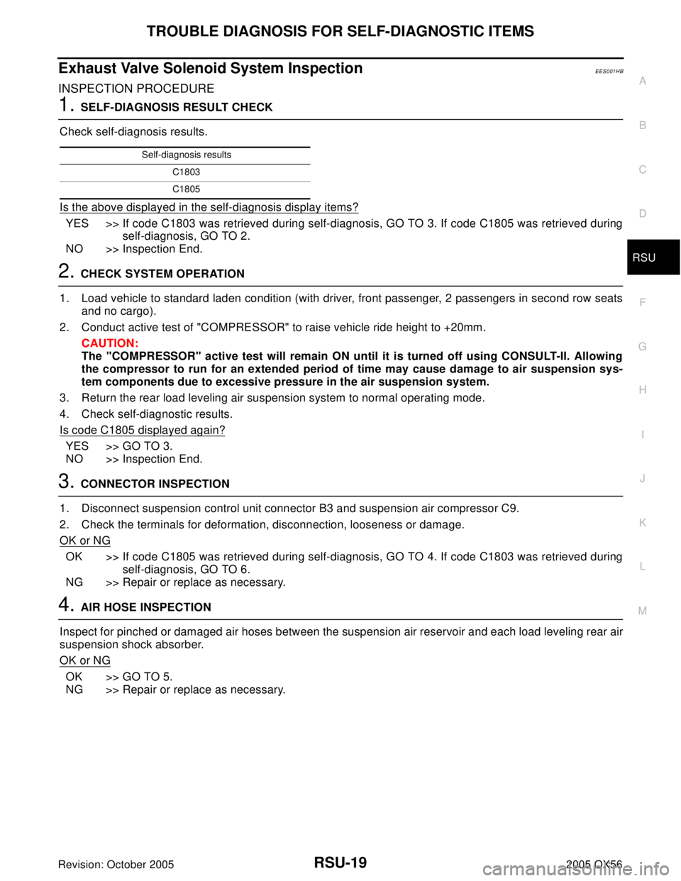
Exhaust Valve Solenoid System InspectionEES001HB
INSPECTION PROCEDURE
1. SELF-DIAGNOSIS RESULT CHECK
Check self-diagnosis results.
Is the above displayed in the self-diagnosis display items?
YES >> If code C1803 was retrieved during self-diagnosis, GO TO 3. If code C1805 was retrieved during
self-diagnosis, GO TO 2.
NO >> Inspection End.
2. CHECK SYSTEM OPERATION
1. Load vehicle to standard laden condition (with driver, front passenger, 2 passengers in second row seats
and no cargo).
2. Conduct active test of "COMPRESSOR" to raise vehicle ride height to +20mm.
CAUTION:
The "COMPRESSOR" active test will remain ON until it is turned off using CONSULT-II. Allowing
the compressor to run for an extended period of time may cause damage to air suspension sys-
tem components due to excessive pressure in the air suspension system.
3. Return the rear load leveling air suspension system to normal operating mode.
4. Check self-diagnostic results.
Is code C1805 displayed again?
YES >> GO TO 3.
NO >> Inspection End.
3. CONNECTOR INSPECTION
1. Disconnect suspension control unit connector B3 and suspension air compressor C9.
2. Check the terminals for deformation, disconnection, looseness or damage.
OK or NG
OK >> If code C1805 was retrieved during self-diagnosis, GO TO 4. If code C1803 was retrieved during
self-diagnosis, GO TO 6.
NG >> Repair or replace as necessary.
4. AIR HOSE INSPECTION
Inspect for pinched or damaged air hoses between the suspension air reservoir and each load leveling rear air
suspension shock absorber.
OK or NG
OK >> GO TO 5.
NG >> Repair or replace as necessary.
Self-diagnosis results
C1803
C1805
Page 2895 of 3419
RSU-20
TROUBLE DIAGNOSIS FOR SELF-DIAGNOSTIC ITEMS
Revision: October 20052005 QX56
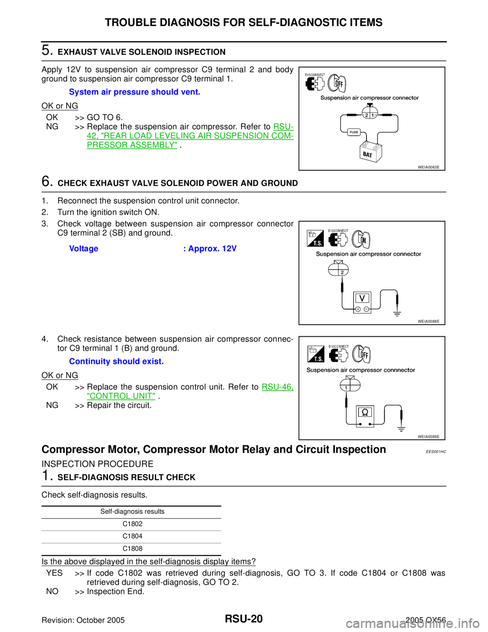
5. EXHAUST VALVE SOLENOID INSPECTION
Apply 12V to suspension air compressor C9 terminal 2 and body
ground to suspension air compressor C9 terminal 1.
OK or NG
OK >> GO TO 6.
NG >> Replace the suspension air compressor. Refer to RSU-
42, "REAR LOAD LEVELING AIR SUSPENSION COM-
PRESSOR ASSEMBLY" .
6. CHECK EXHAUST VALVE SOLENOID POWER AND GROUND
1. Reconnect the suspension control unit connector.
2. Turn the ignition switch ON.
3. Check voltage between suspension air compressor connector
C9 terminal 2 (SB) and ground.
4. Check resistance between suspension air compressor connec-
tor C9 terminal 1 (B) and ground.
OK or NG
OK >> Replace the suspension control unit. Refer to RSU-46,
"CONTROL UNIT" .
NG >> Repair the circuit.
Compressor Motor, Compressor Motor Relay and Circuit InspectionEES001HC
INSPECTION PROCEDURE
1. SELF-DIAGNOSIS RESULT CHECK
Check self-diagnosis results.
Is the above displayed in the self-diagnosis display items?
YES >> If code C1802 was retrieved during self-diagnosis, GO TO 3. If code C1804 or C1808 was
retrieved during self-diagnosis, GO TO 2.
NO >> Inspection End.System air pressure should vent.
WEIA0063E
Voltage : Approx. 12V
WEIA0088E
Continuity should exist.
WEIA0089E
Self-diagnosis results
C1802
C1804
C1808
Page 2896 of 3419
TROUBLE DIAGNOSIS FOR SELF-DIAGNOSTIC ITEMS
RSU-21
C
D
F
G
H
I
J
K
L
MA
B
RSU
Revision: October 20052005 QX56
2. CHECK SYSTEM OPERATION
1. Load vehicle to standard laden condition (with driver, front passenger, 2 passengers in second row seats
and no cargo).
2. Conduct active test of "EXHAUST SOLENOID" to lower vehicle ride height to -20mm.
3. Return the rear load leveling air suspension system to normal operating mode.
4. Check self-diagnostic results.
Is code C1804 or C1808 displayed again?
YES >> GO TO 3.
NO >> Inspection End.
3. CONNECTOR INSPECTION
1. Disconnect suspension control unit connector B3 and suspension air compressor C9.
2. Check the terminals for deformation, disconnection, looseness or damage.
OK or NG
OK >> If code C1804 or C1808 was retrieved during self-diagnosis, GO TO 4. If code C1802 was
retrieved during self-diagnosis, GO TO 6.
NG >> Repair or replace as necessary.
4. AIR HOSE INSPECTION
Inspect for pinched or damaged air hoses between the suspension air reservoir and each load leveling rear air
suspension shock absorber.
OK or NG
OK >> GO TO 5.
NG >> Repair or replace as necessary.
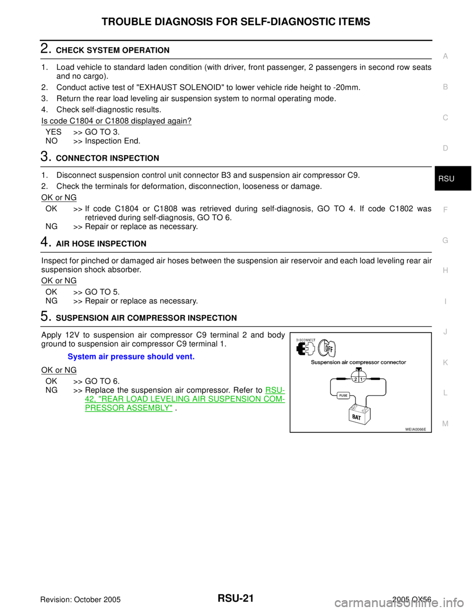
5. SUSPENSION AIR COMPRESSOR INSPECTION
Apply 12V to suspension air compressor C9 terminal 2 and body
ground to suspension air compressor C9 terminal 1.
OK or NG
OK >> GO TO 6.
NG >> Replace the suspension air compressor. Refer to RSU-
42, "REAR LOAD LEVELING AIR SUSPENSION COM-
PRESSOR ASSEMBLY" . System air pressure should vent.
WEIA0066E
Page 2899 of 3419
RSU-24
TROUBLE DIAGNOSES FOR SYMPTOMS
Revision: October 20052005 QX56
4. CHECK GENERATOR SIGNAL INPUT
1. Start the engine.
2. Check voltage between suspension control unit connector B3
terminal 15 (BR/W) and ground.
OK or NG
OK >> Replace the suspension control unit. Refer to RSU-46,
"CONTROL UNIT" .
NG >> Repair the circuit.
CK SUSP Indicator Lamp Stays On When Ignition Switch Is Turned OnEES001HE
1. CARRY OUT SELF-DIAGNOSIS
Carry out self-diagnosis. Refer to RSU-14, "
SELF-DIAGNOSIS" .
Are malfunctions detected in self-diagnosis?
YES >> Refer to RSU-16, "Display Item List" .
NO >> Refer to DI-30, "
WARNING LAMPS" . Voltage : Approx. 12V
WEIA0071E
Page 2903 of 3419
RSU-28
REAR SUSPENSION ASSEMBLY
Revision: October 20052005 QX56
�Check with the manufacturer of your specific alignment machine for their recommended Service/Cali-
bration Schedule.
THE ALIGNMENT PROCESS
IMPORTANT: Use only the alignment specifications listed in this Service Manual. Refer to RSU-47, "Wheel
Alignment"
1. When displaying the alignment settings, many alignment machines use “indicators”: (Green/red, plus or
minus, Go/No Go). Do NOT use these indicators.
�The alignment specifications programmed into your alignment machine that operate these indicators
may not be correct.
�This may result in an ERROR.
2. Some newer alignment machines are equipped with an optional “Rolling Compensation” method to “com-
pensate” the sensors (alignment targets or head units). Do NOT use this “Rolling Compensation”
method.
�Use the “Jacking Compensation” method. After installing the alignment targets or head units, raise the
vehicle and rotate the wheels 1/2 turn both ways.
�See Instructions in the alignment machine you are using for more information.
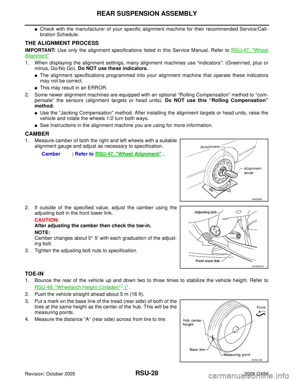
CAMBER
1. Measure camber of both the right and left wheels with a suitable
alignment gauge and adjust as necessary to specification.
2. If outside of the specified value, adjust the camber using the
adjusting bolt in the front lower link.
CAUTION:
After adjusting the camber then check the toe-in.
NOTE:
Camber changes about 0° 5' with each graduation of the adjust-
ing bolt.
3. Tighten the adjusting bolt nuts to specification.
TOE-IN
1. Bounce the rear of the vehicle up and down two to three times to stabilize the vehicle height. Refer to
RSU-48, "
Wheelarch Height (Unladen*1 )" .
2. Push the vehicle straight ahead about 5 m (16 ft).
3. Put a mark on the base line of the tread (rear side) of both of the
tires at the same height as the center of the hub. This will be the
measuring points.
4. Measure the distance “A” (rear side) across from tire to tire.Camber : Refer to RSU-47, "
Wheel Alignment" .
SRA0 96 A
LEIA0041E
SFA614B
Page 2945 of 3419
SC-8
BATTERY
Revision: October 20052005 QX56
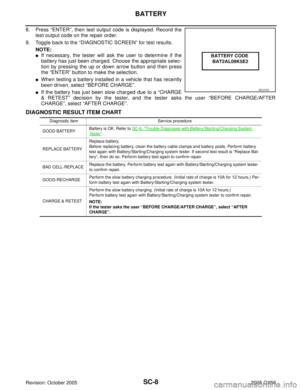
8. Press “ENTER”, then test output code is displayed. Record the
test output code on the repair order.
9. Toggle back to the “DIAGNOSTIC SCREEN” for test results.
NOTE:
�If necessary, the tester will ask the user to determine if the
battery has just been charged. Choose the appropriate selec-
tion by pressing the up or down arrow button and then press
the “ENTER” button to make the selection.
�When testing a battery installed in a vehicle that has recently
been driven, select “BEFORE CHARGE”.
�If the battery has just been slow charged due to a “CHARGE
& RETEST” decision by the tester, and the tester asks the user “BEFORE CHARGE/AFTER
CHARGE”, select “AFTER CHARGE”.
DIAGNOSTIC RESULT ITEM CHART
SEL576X
Diagnostic item Service procedure
GOOD BATTERYBattery is OK. Refer to SC-6, "
Trouble Diagnoses with Battery/Starting/Charging System
Te s t e r" .
REPLACE BATTERYReplace battery.
Before replacing battery, clean the battery cable clamps and battery posts. Perform battery
test again with Battery/Starting/Charging system tester. If second test result is “Replace Bat-
tery”, then do so. Perform battery test again to confirm repair.
BAD CELL-REPLACEReplace the battery. Perform battery test again with Battery/Starting/Charging system tester
to confirm repair.
GOOD-RECHARGEPerform the slow battery charging procedure. (Initial rate of charge is 10A for 12 hours.) Per-
form battery test again with Battery/Starting/Charging system tester.
CHARGE & RETESTPerform the slow battery charging. (Initial rate of charge is 10A for 12 hours.)
Perform battery test again with Battery/Starting/Charging system tester to confirm repair.
NOTE:
If the tester asks the user “BEFORE CHARGE/AFTER CHARGE”, select “AFTER
CHARGE”.
Page 2949 of 3419
SC-12
STARTING SYSTEM
Revision: October 20052005 QX56
Trouble Diagnoses with Battery/Starting/Charging System TesterEKS00B7D
NOTE:
To ensure a complete and thorough diagnosis, the battery, starter and generator test segments must be done
as a set from start to finish.
1. Turn off all loads on the vehicle electrical system.
2. Perform battery test with Battery/Starting/Charging system
tester. Refer to SC-12, "
Trouble Diagnoses with Battery/Starting/
Charging System Tester" .
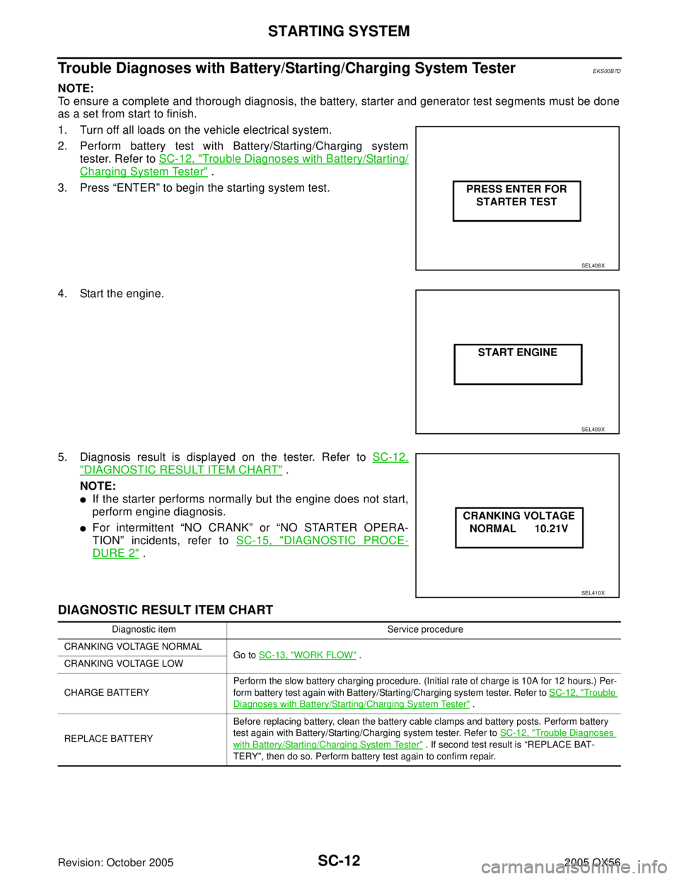
3. Press “ENTER” to begin the starting system test.
4. Start the engine.
5. Diagnosis result is displayed on the tester. Refer to SC-12,
"DIAGNOSTIC RESULT ITEM CHART" .
NOTE:
�If the starter performs normally but the engine does not start,
perform engine diagnosis.
�For intermittent “NO CRANK” or “NO STARTER OPERA-
TION” incidents, refer to SC-15, "
DIAGNOSTIC PROCE-
DURE 2" .
DIAGNOSTIC RESULT ITEM CHART
SEL408X
SEL409X
SEL410X
Diagnostic item Service procedure
CRANKING VOLTAGE NORMAL
Go to SC-13, "
WORK FLOW" .
CRANKING VOLTAGE LOW
CHARGE BATTERYPerform the slow battery charging procedure. (Initial rate of charge is 10A for 12 hours.) Per-
form battery test again with Battery/Starting/Charging system tester. Refer to SC-12, "
Trouble
Diagnoses with Battery/Starting/Charging System Tester" .
REPLACE BATTERYBefore replacing battery, clean the battery cable clamps and battery posts. Perform battery
test again with Battery/Starting/Charging system tester. Refer to SC-12, "
Trouble Diagnoses
with Battery/Starting/Charging System Tester" . If second test result is “REPLACE BAT-
TERY”, then do so. Perform battery test again to confirm repair.