Page 2500 of 3419
AUTO LIGHT SYSTEM
LT-53
C
D
E
F
G
H
I
J
L
MA
B
LT
Revision: October 20052005 QX56
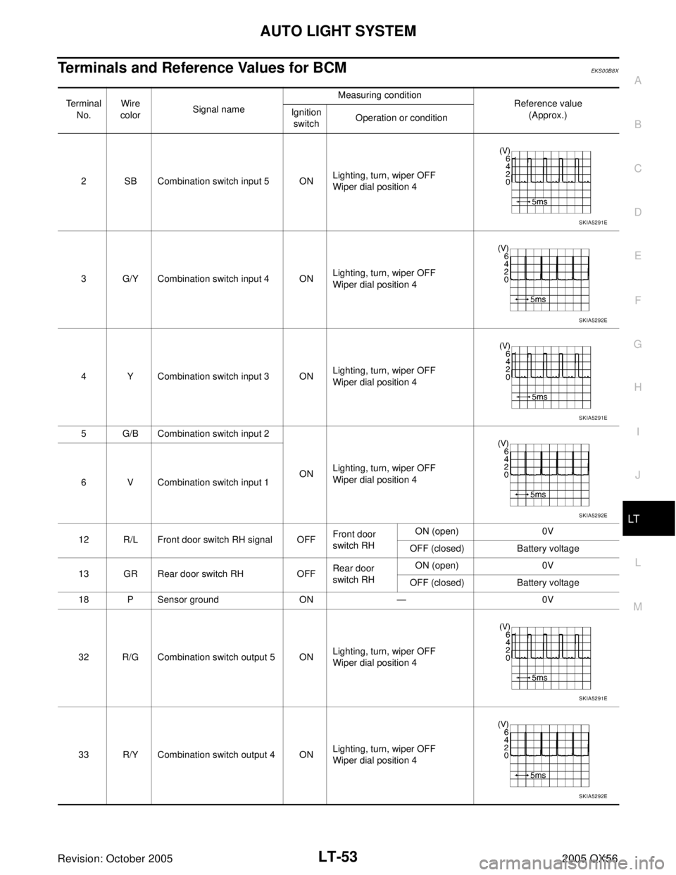
Terminals and Reference Values for BCMEKS00B8X
Terminal
No.Wire
colorSignal nameMeasuring condition
Reference value
(Approx.) Ignition
switchOperation or condition
2 SB Combination switch input 5 ONLighting, turn, wiper OFF
Wiper dial position 4
3 G/Y Combination switch input 4 ONLighting, turn, wiper OFF
Wiper dial position 4
4 Y Combination switch input 3 ONLighting, turn, wiper OFF
Wiper dial position 4
5 G/B Combination switch input 2
ONLighting, turn, wiper OFF
Wiper dial position 4
6 V Combination switch input 1
12 R/L Front door switch RH signal OFFFront door
switch RH ON (open) 0V
OFF (closed) Battery voltage
13 GR Rear door switch RH OFFRear door
switch RHON (open) 0V
OFF (closed) Battery voltage
18 P Sensor ground ON — 0V
32 R/G Combination switch output 5 ONLighting, turn, wiper OFF
Wiper dial position 4
33 R/Y Combination switch output 4 ONLighting, turn, wiper OFF
Wiper dial position 4
SKIA5291E
SKIA5292E
SKIA5291E
SKIA5292E
SKIA5291E
SKIA5292E
Page 2501 of 3419
LT-54
AUTO LIGHT SYSTEM
Revision: October 20052005 QX56
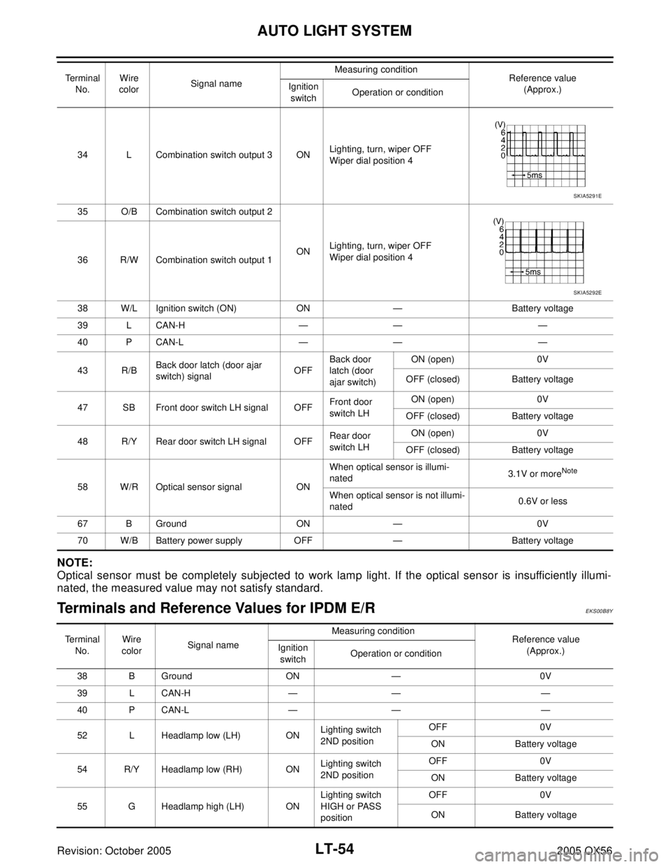
NOTE:
Optical sensor must be completely subjected to work lamp light. If the optical sensor is insufficiently illumi-
nated, the measured value may not satisfy standard.
Terminals and Reference Values for IPDM E/REKS00B8Y
34 L Combination switch output 3 ONLighting, turn, wiper OFF
Wiper dial position 4
35 O/B Combination switch output 2
ONLighting, turn, wiper OFF
Wiper dial position 4
36 R/W Combination switch output 1
38 W/L Ignition switch (ON) ON — Battery voltage
39 L CAN-H — — —
40 P CAN-L — — —
43 R/BBack door latch (door ajar
switch) signalOFFBack door
latch (door
ajar switch)ON (open) 0V
OFF (closed) Battery voltage
47 SB Front door switch LH signal OFFFront door
switch LH ON (open) 0V
OFF (closed) Battery voltage
48 R/Y Rear door switch LH signal OFFRear door
switch LH ON (open) 0V
OFF (closed) Battery voltage
58 W/R Optical sensor signal ONWhen optical sensor is illumi-
nated3.1V or more
Note
When optical sensor is not illumi-
nated0.6V or less
67 B Ground ON — 0V
70 W/B Battery power supply OFF — Battery voltage Te r m i n a l
No.Wire
colorSignal nameMeasuring condition
Reference value
(Approx.) Ignition
switchOperation or condition
SKIA5291E
SKIA5292E
Te r m i n a l
No.Wire
colorSignal nameMeasuring condition
Reference value
(Approx.) Ignition
switchOperation or condition
38 B Ground ON — 0V
39 L CAN-H — — —
40 P CAN-L — — —
52 L Headlamp low (LH) ONLighting switch
2ND positionOFF 0V
ON Battery voltage
54 R/Y Headlamp low (RH) ONLighting switch
2ND positionOFF 0V
ON Battery voltage
55 G Headlamp high (LH) ONLighting switch
HIGH or PASS
positionOFF 0V
ON Battery voltage
Page 2502 of 3419
AUTO LIGHT SYSTEM
LT-55
C
D
E
F
G
H
I
J
L
MA
B
LT
Revision: October 20052005 QX56
1 USA
2 Canada
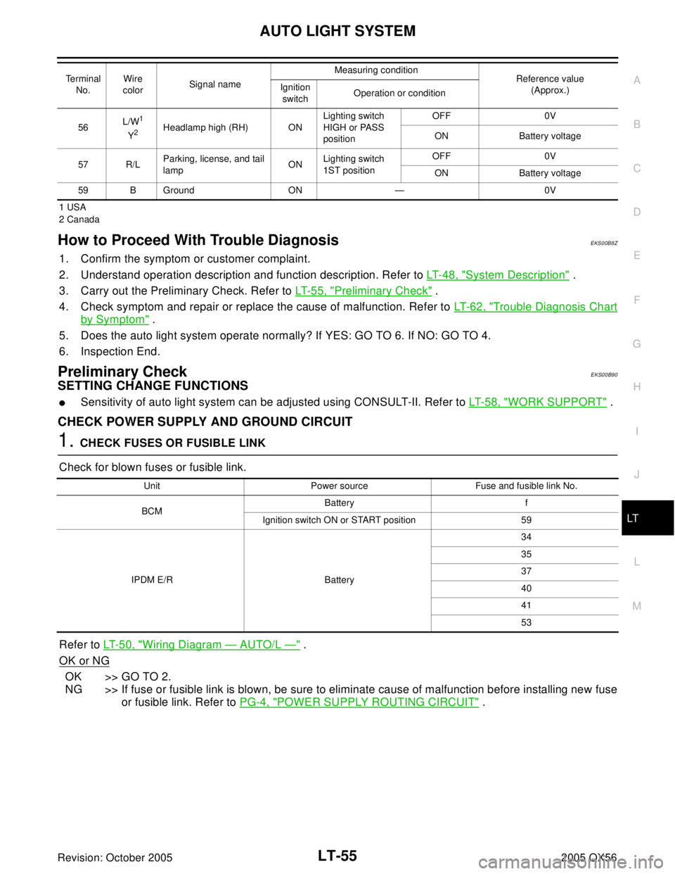
How to Proceed With Trouble DiagnosisEKS00B8Z
1. Confirm the symptom or customer complaint.
2. Understand operation description and function description. Refer to LT- 4 8 , "
System Description" .
3. Carry out the Preliminary Check. Refer to LT- 5 5 , "
Preliminary Check" .
4. Check symptom and repair or replace the cause of malfunction. Refer to LT- 6 2 , "
Trouble Diagnosis Chart
by Symptom" .
5. Does the auto light system operate normally? If YES: GO TO 6. If NO: GO TO 4.
6. Inspection End.
Preliminary CheckEKS00B90
SETTING CHANGE FUNCTIONS
�Sensitivity of auto light system can be adjusted using CONSULT-II. Refer to LT-58, "WORK SUPPORT" .
CHECK POWER SUPPLY AND GROUND CIRCUIT
1. CHECK FUSES OR FUSIBLE LINK
Check for blown fuses or fusible link.
Refer to LT- 5 0 , "
Wiring Diagram — AUTO/L —" .
OK or NG
OK >> GO TO 2.
NG >> If fuse or fusible link is blown, be sure to eliminate cause of malfunction before installing new fuse
or fusible link. Refer to PG-4, "
POWER SUPPLY ROUTING CIRCUIT" .
56L/W1
Y2Headlamp high (RH) ONLighting switch
HIGH or PASS
positionOFF 0V
ON Battery voltage
57 R/LParking, license, and tail
lampONLighting switch
1ST positionOFF 0V
ON Battery voltage
59 B Ground ON — 0V Te r m i n a l
No.Wire
colorSignal nameMeasuring condition
Reference value
(Approx.) Ignition
switchOperation or condition
Unit Power source Fuse and fusible link No.
BCMBattery f
Ignition switch ON or START position 59
IPDM E/R Battery34
35
37
40
41
53
Page 2503 of 3419
LT-56
AUTO LIGHT SYSTEM
Revision: October 20052005 QX56
2. CHECK POWER SUPPLY CIRCUIT
1. Disconnect BCM connectors.
2. Check voltage between BCM harness connector and ground.
OK or NG
OK >> GO TO 3.
NG >> Check harness for open between BCM and fuse or fus-
ible link.
3. CHECK GROUND CIRCUIT
Check continuity between BCM harness connector and ground.
OK or NG
OK >> Inspection End.
NG >> Check ground circuit harness.
Terminals Ignition switch position
(+)
(–) OFF ACC ON
ConnectorTe r m i n a l
(Wire color)
M18 38 (W/L)
Ground0V 0VBattery
voltage
M20 70 (W/B)Battery
voltageBattery
voltageBattery
voltage
WKIA1436E
Te r m i n a l s
Continuity
ConnectorTe r m i n a l
(Wire color)
M20 67 (B) Ground Yes
LIIA0915E
Page 2517 of 3419

LT-70
FRONT FOG LAMP
Revision: October 20052005 QX56
�through grounds E9, E15 and E24.
FOG LAMP OPERATION
The fog lamp switch is built into the combination switch. The lighting switch must be in the 2ND position or
AUTO position (LOW beam is ON) and the fog lamp switch must be ON for fog lamp operation.
With the fog lamp switch in the ON position, the CPU of the IPDM E/R grounds the coil side of the fog lamp
relay. The fog lamp relay then directs power
�through 20A fuse (No. 56, located in the IPDM E/R)
�through IPDM E/R terminal 50
�to front turn/fog lamp LH terminal 1, and
�through IPDM E/R terminal 51
�to front turn/fog lamp RH terminal 1.
Ground is supplied
�to front turn/fog lamp LH and RH terminal 3
�through grounds E9, E15 and E24.
With power and ground supplied, the front fog lamps illuminate.
COMBINATION SWITCH READING FUNCTION
Refer to BCS-3, "COMBINATION SWITCH READING FUNCTION" .
EXTERIOR LAMP BATTERY SAVER CONTROL
When the combination switch (lighting switch) is in the 2ND position (ON), the fog lamp switch is ON, and the
ignition switch is turned from ON or ACC to OFF, the battery saver control feature is activated.
Under this condition, the fog lamps (and headlamps) remain illuminated for 5 minutes, then the fog lamps (and
headlamps) are turned off.
Exterior lamp battery saver control mode can be changed by the function setting of CONSULT-II.
CAN Communication System DescriptionEKS00B9D
Refer to LAN-5, "CAN COMMUNICATION" .
Page 2521 of 3419
LT-74
FRONT FOG LAMP
Revision: October 20052005 QX56
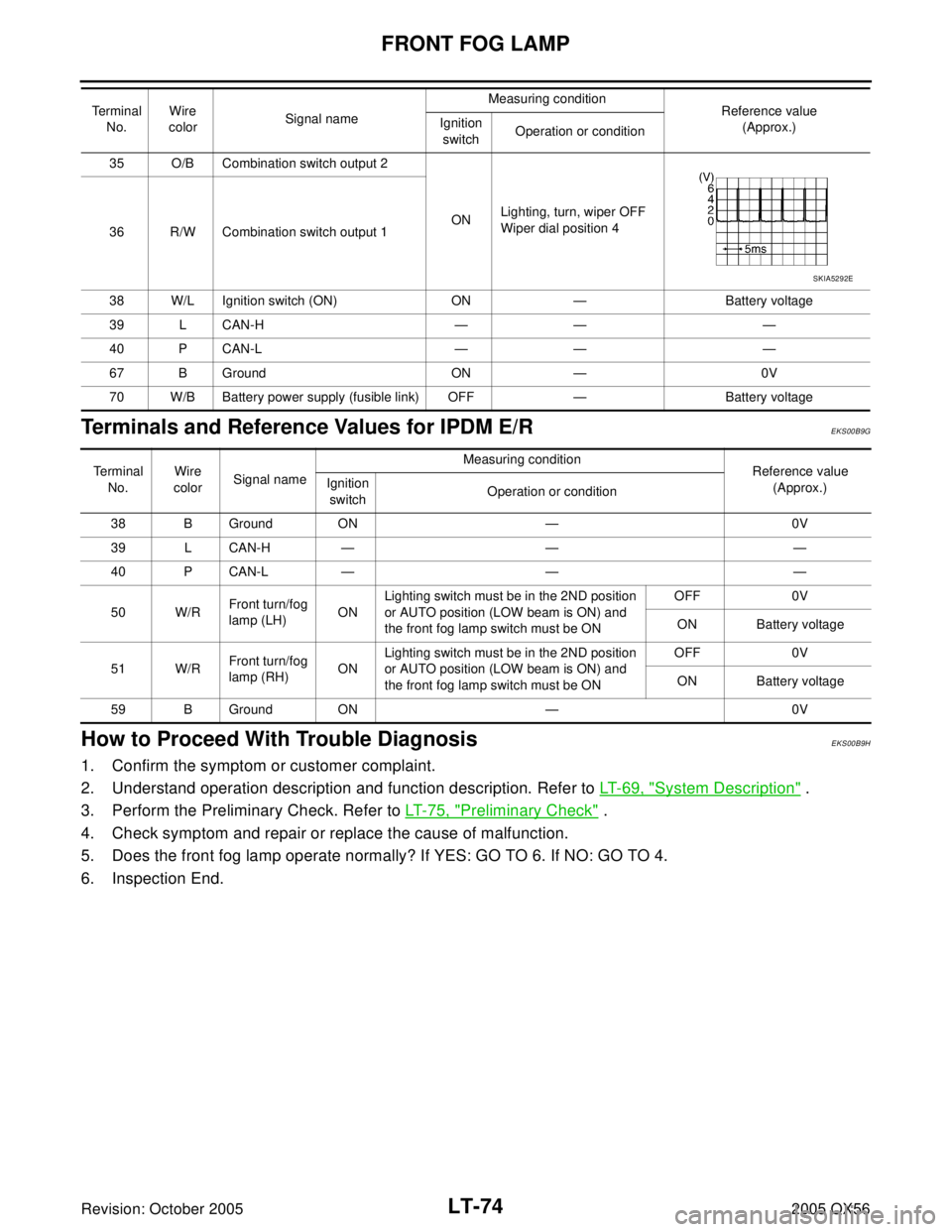
Terminals and Reference Values for IPDM E/REKS00B9G
How to Proceed With Trouble DiagnosisEKS00B9H
1. Confirm the symptom or customer complaint.
2. Understand operation description and function description. Refer to LT-69, "
System Description" .
3. Perform the Preliminary Check. Refer to LT-75, "
Preliminary Check" .
4. Check symptom and repair or replace the cause of malfunction.
5. Does the front fog lamp operate normally? If YES: GO TO 6. If NO: GO TO 4.
6. Inspection End.
35 O/B Combination switch output 2
ONLighting, turn, wiper OFF
Wiper dial position 4
36 R/W Combination switch output 1
38 W/L Ignition switch (ON) ON — Battery voltage
39 L CAN-H — — —
40 P CAN-L — — —
67 B Ground ON — 0V
70 W/B Battery power supply (fusible link) OFF — Battery voltage Terminal
No.Wire
colorSignal nameMeasuring condition
Reference value
(Approx.) Ignition
switchOperation or condition
SKIA5292E
Te r m i n a l
No.Wire
colorSignal nameMeasuring condition
Reference value
(Approx.) Ignition
switchOperation or condition
38 B Ground ON — 0V
39 L CAN-H — — —
40 P CAN-L — — —
50 W/RFront turn/fog
lamp (LH)ONLighting switch must be in the 2ND position
or AUTO position (LOW beam is ON) and
the front fog lamp switch must be ONOFF 0V
ON Battery voltage
51 W/RFront turn/fog
lamp (RH) ONLighting switch must be in the 2ND position
or AUTO position (LOW beam is ON) and
the front fog lamp switch must be ONOFF 0V
ON Battery voltage
59 B Ground ON — 0V
Page 2522 of 3419
FRONT FOG LAMP
LT-75
C
D
E
F
G
H
I
J
L
MA
B
LT
Revision: October 20052005 QX56
Preliminary CheckEKS00B9I
CHECK POWER SUPPLY AND GROUND CIRCUIT
1. CHECK FUSES OR FUSIBLE LINK
Check for blown fuses or fusible link.
Refer to LT- 7 1 , "
Wiring Diagram — F/FOG —" .
OK or NG
OK >> GO TO 2.
NG >> If fuse or fusible link is blown, be sure to eliminate cause of malfunction before installing new fuse
or fusible link. Refer to PG-4, "
POWER SUPPLY ROUTING CIRCUIT" .
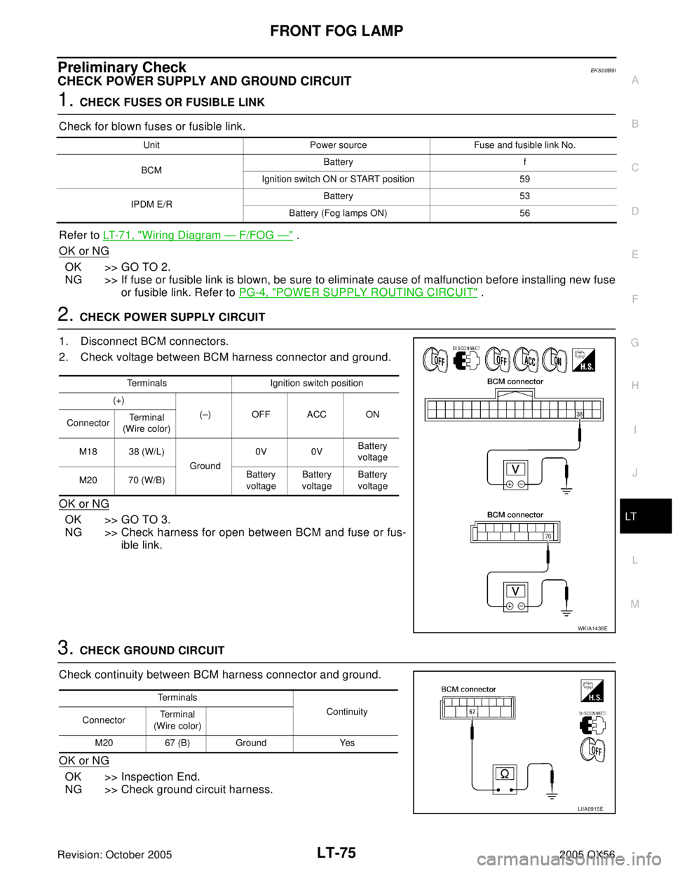
2. CHECK POWER SUPPLY CIRCUIT
1. Disconnect BCM connectors.
2. Check voltage between BCM harness connector and ground.
OK or NG
OK >> GO TO 3.
NG >> Check harness for open between BCM and fuse or fus-
ible link.
3. CHECK GROUND CIRCUIT
Check continuity between BCM harness connector and ground.
OK or NG
OK >> Inspection End.
NG >> Check ground circuit harness.
Unit Power source Fuse and fusible link No.
BCMBattery f
Ignition switch ON or START position 59
IPDM E/RBattery 53
Battery (Fog lamps ON) 56
Terminals Ignition switch position
(+)
(–) OFF ACC ON
ConnectorTerminal
(Wire color)
M18 38 (W/L)
Ground0V 0VBattery
voltage
M20 70 (W/B)Battery
voltageBattery
voltageBattery
voltage
WKIA1436E
Terminals
Continuity
ConnectorTe r m i n a l
(Wire color)
M20 67 (B) Ground Yes
LIIA0915E
Page 2524 of 3419
FRONT FOG LAMP
LT-77
C
D
E
F
G
H
I
J
L
MA
B
LT
Revision: October 20052005 QX56
4. IPDM E/R INSPECTION
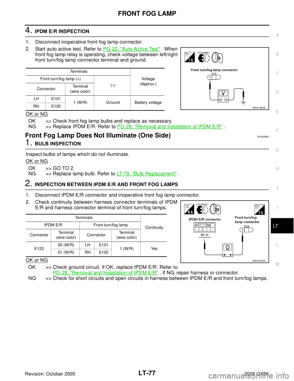
1. Disconnect inoperative front fog lamp connector.
2. Start auto active test. Refer to PG-22, "
Auto Active Test" . When
front fog lamp relay is operating, check voltage between left/right
front turn/fog lamp connector terminal and ground.
OK or NG
OK >> Check front fog lamp bulbs and replace as necessary.
NG >> Replace IPDM E/R. Refer to PG-28, "
Removal and Installation of IPDM E/R" .
Front Fog Lamp Does Not Illuminate (One Side)EKS00B9L
1. BULB INSPECTION
Inspect bulbs of lamps which do not illuminate.
OK or NG
OK >> GO TO 2.
NG >> Replace lamp bulb. Refer to LT- 7 9 , "
Bulb Replacement" .
2. INSPECTION BETWEEN IPDM E/R AND FRONT FOG LAMPS
1. Disconnect IPDM E/R connector and inoperative front fog lamp connector.
2. Check continuity between harness connector terminals of IPDM
E/R and harness connector terminal of front turn/fog lamps.
OK or NG
OK >> Check ground circuit. If OK, replace IPDM E/R. Refer to
PG-28, "
Removal and Installation of IPDM E/R" . If NG, repair harness or connector.
NG >> Check for short circuits and open circuits in harness between IPDM E/R and front turn/fog lamps.
Terminals
Vo l ta g e
(Approx.) Front turn/fog lamp (+)
(–)
ConnectorTe r m i n a l
(wire color)
LH E101
1 (W/R) Ground Battery voltage
RH E102
WKIA1884E
Te r m i n a l s
Continuity IPDM E/R Front turn/fog lamp
ConnectorTe r m i n a l
(wire color)ConnectorTe r m i n a l
(wire color)
E12350 (W/R) LH E101
1 (W/R) Yes
51 (W/R) RH E102
WKIA3553E