Page 2891 of 3419

RSU-16
TROUBLE DIAGNOSIS
Revision: October 20052005 QX56
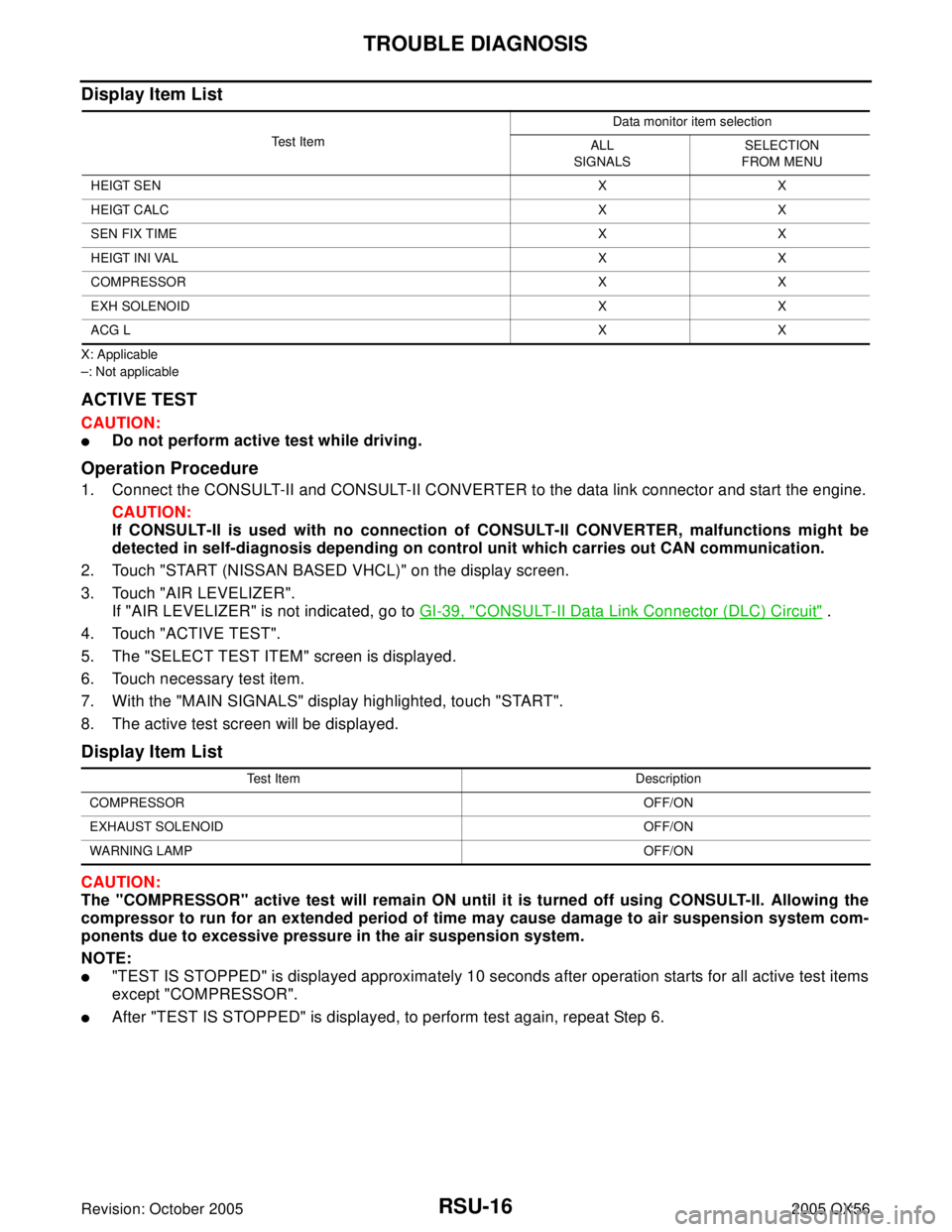
Display Item List
X: Applicable
–: Not applicable
ACTIVE TEST
CAUTION:
�Do not perform active test while driving.
Operation Procedure
1. Connect the CONSULT-II and CONSULT-II CONVERTER to the data link connector and start the engine.
CAUTION:
If CONSULT-II is used with no connection of CONSULT-II CONVERTER, malfunctions might be
detected in self-diagnosis depending on control unit which carries out CAN communication.
2. Touch "START (NISSAN BASED VHCL)" on the display screen.
3. Touch "AIR LEVELIZER".
If "AIR LEVELIZER" is not indicated, go to GI-39, "
CONSULT-II Data Link Connector (DLC) Circuit" .
4. Touch "ACTIVE TEST".
5. The "SELECT TEST ITEM" screen is displayed.
6. Touch necessary test item.
7. With the "MAIN SIGNALS" display highlighted, touch "START".
8. The active test screen will be displayed.
Display Item List
CAUTION:
The "COMPRESSOR" active test will remain ON until it is turned off using CONSULT-II. Allowing the
compressor to run for an extended period of time may cause damage to air suspension system com-
ponents due to excessive pressure in the air suspension system.
NOTE:
�"TEST IS STOPPED" is displayed approximately 10 seconds after operation starts for all active test items
except "COMPRESSOR".
�After "TEST IS STOPPED" is displayed, to perform test again, repeat Step 6.
Te s t I t e mData monitor item selection
ALL
SIGNALSSELECTION
FROM MENU
HEIGT SENXX
HEIGT CALCXX
SEN FIX TIMEXX
HEIGT INI VALXX
COMPRESSOR X X
EXH SOLENOID X X
ACG LXX
Test Item Description
COMPRESSOROFF/ON
EXHAUST SOLENOIDOFF/ON
WARNING LAMPOFF/ON
Page 2959 of 3419
SC-22
CHARGING SYSTEM
Revision: October 20052005 QX56
DIAGNOSTIC PROCEDURE 1
Check Charge Warning Lamp Circuit
1. CHECK CHARGE WARNING LAMP CIRCUIT CONNECTION
1. Turn the ignition switch OFF.
2. Check to see if terminal 3 is clean and tight.
OK or NG
OK >> GO TO 2.
NG >> Repair terminal 3 connection. Confirm repair by performing complete Battery/Starting/Charging
system test.
2. CHECK CHARGE WARNING LAMP CIRCUIT
1. Disconnect E205 connector from generator.
2. Apply ground to connector E205 terminal 3 (BR/W) with the igni-
tion switch in the ON position.
OK or NG
OK >> GO TO SC-21, "WORK FLOW" .
NG >> Check the following.
�10A fuse [No. 14, located in fuse block (J/B)]
�Charge warning lamp
�Harness for open or short between combination
meter and fuse
�Harness for open or short between combination meter and generator Charge warning lamp should
light up.
WKIA2110E
Page 2961 of 3419

SC-24
CHARGING SYSTEM
Revision: October 20052005 QX56
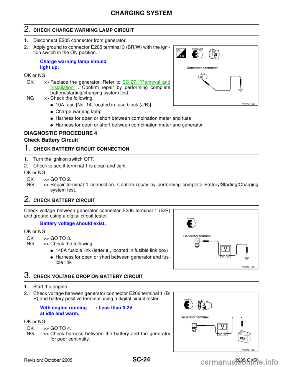
2. CHECK CHARGE WARNING LAMP CIRCUIT
1. Disconnect E205 connector from generator.
2. Apply ground to connector E205 terminal 3 (BR/W) with the igni-
tion switch in the ON position.
OK or NG
OK >> Replace the generator. Refer to SC-27, "Removal and
Installation" . Confirm repair by performing complete
battery/starting/charging system test.
NG >> Check the following.
�10A fuse [No. 14, located in fuse block (J/B)]
�Charge warning lamp
�Harness for open or short between combination meter and fuse
�Harness for open or short between combination meter and generator
DIAGNOSTIC PROCEDURE 4
Check Battery Circuit
1. CHECK BATTERY CIRCUIT CONNECTION
1. Turn the ignition switch OFF.
2. Check to see if terminal 1 is clean and tight.
OK or NG
OK >> GO TO 2.
NG >> Repair terminal 1 connection. Confirm repair by performing complete Battery/Starting/Charging
system test.
2. CHECK BATTERY CIRCUIT
Check voltage between generator connector E206 terminal 1 (B/R)
and ground using a digital circuit tester.
OK or NG
OK >> GO TO 3.
NG >> Check the following.
�140A fusible link (letter a , located in fusible link box)
�Harness for open or short between generator and fus-
ible link
3. CHECK VOLTAGE DROP ON BATTERY CIRCUIT
1. Start the engine.
2. Check voltage between generator connector E206 terminal 1 (B/
R) and battery positive terminal using a digital circuit tester.
OK or NG
OK >> GO TO 4.
NG >> Check harness between the battery and the generator
for poor continuity. Charge warning lamp should
light up.
WKIA2110E
Battery voltage should exist.
W K I A 2111 E
With engine running
at idle and warm.: Less than 0.2V
WKIA2112E
Page 3117 of 3419
SRS-38
TROUBLE DIAGNOSIS
Revision: October 20052005 QX56
Trouble Diagnosis Without CONSULT-IIEHS0016U
DIAGNOSTIC PROCEDURE 6
Inspect SRS Malfunction Using "AIR BAG" Warning Lamp—Diagnosis Mode
NOTE:
SRS will not enter Diagnosis mode if no malfunction is detected in User mode.
1. Turn ignition switch ON.
2. After “AIR BAG” warning lamp lights for 7 seconds, turn ignition switch OFF within 1 second.
3. Wait more than 3 seconds.
4. Repeat steps 1 to 3 two more times (3 times total).
5. Turn ignition switch ON.
SRS is now in Diagnosis mode.
"AIR BAG" warning lamp operates in Diagnosis mode as follows:
Page 3178 of 3419

TROUBLE DIAGNOSIS
TF-35
C
E
F
G
H
I
J
K
L
MA
B
TF
Revision: October 20052005 QX56
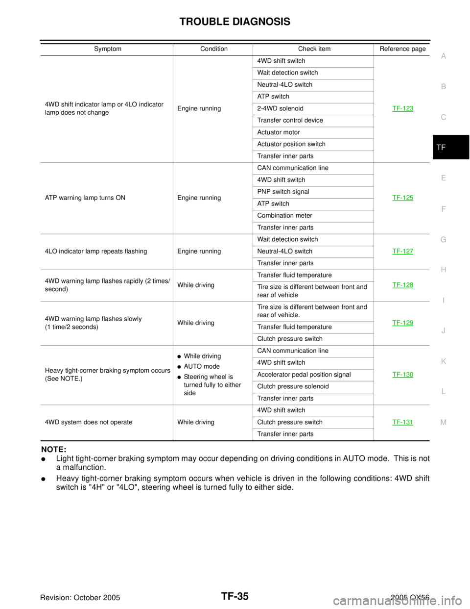
NOTE:
�Light tight-corner braking symptom may occur depending on driving conditions in AUTO mode. This is not
a malfunction.
�Heavy tight-corner braking symptom occurs when vehicle is driven in the following conditions: 4WD shift
switch is "4H" or "4LO", steering wheel is turned fully to either side.
4WD shift indicator lamp or 4LO indicator
lamp does not changeEngine running4WD shift switch
TF-123
Wait detection switch
Neutral-4LO switch
ATP switch
2-4WD solenoid
Transfer control device
Actuator motor
Actuator position switch
Transfer inner parts
ATP warning lamp turns ON Engine runningCAN communication line
TF-125
4WD shift switch
PNP switch signal
ATP switch
Combination meter
Transfer inner parts
4LO indicator lamp repeats flashing Engine runningWait detection switch
TF-127
Neutral-4LO switch
Transfer inner parts
4WD warning lamp flashes rapidly (2 times/
second)While drivingTransfer fluid temperature
TF-128
Tire size is different between front and
rear of vehicle
4WD warning lamp flashes slowly
(1 time/2 seconds)While drivingTire size is different between front and
rear of vehicle.
TF-129
Transfer fluid temperature
Clutch pressure switch
Heavy tight-corner braking symptom occurs
(See NOTE.)
�While driving
�AUTO mode
�Steering wheel is
turned fully to either
sideCAN communication line
TF-130
4WD shift switch
Accelerator pedal position signal
Clutch pressure solenoid
Transfer inner parts
4WD system does not operate While driving4WD shift switch
TF-131
Clutch pressure switch
Transfer inner parts Symptom Condition Check item Reference page