Page 1447 of 3419
EC-256Revision: October 2005
DTC P0181 FTT SENSOR
2005 QX56
Diagnostic ProcedureUBS00H38
1. CHECK COMBINATION METER FUNCTION
Refer to DI-5, "
COMBINATION METERS" .
OK or NG
OK >> GO TO 2.
NG >> Go to DI-22, "
Fuel Level Sensor Unit Inspection" .
2. CHECK GROUND CONNECTIONS
1. Turn ignition switch OFF.
2. Loosen and retighten three ground screws on the body.
Refer to EC-162, "
Ground Inspection" .
OK or NG
OK >> GO TO 3.
NG >> Repair or replace ground connections.
3. CHECK FUEL TANK TEMPERATURE SENSOR POWER SUPPLY CIRCUIT
1. Disconnect “fuel level sensor unit and fuel pump” harness con-
nector.
2. Turn ignition switch ON.
3. Check voltage between “fuel level sensor unit and fuel pump”
terminal 4 and ground with CONSULT-II or tester.
OK or NG
OK >> GO TO 5.
NG >> GO TO 4.
BBIA0354E
BBIA0583E
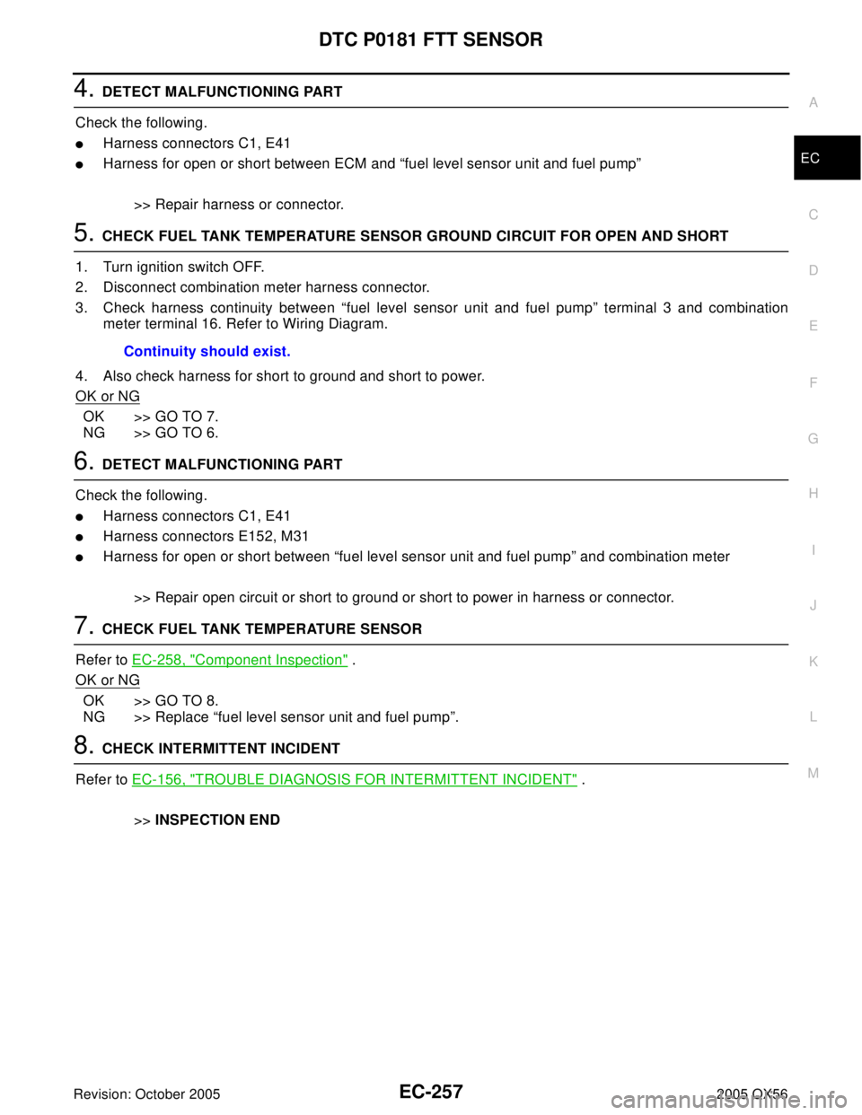
Voltage: Approximately 5V
PBIB0932E
Page 1448 of 3419

DTC P0181 FTT SENSOR
EC-257
C
D
E
F
G
H
I
J
K
L
MA
EC
Revision: October 20052005 QX56
4. DETECT MALFUNCTIONING PART
Check the following.
�Harness connectors C1, E41
�Harness for open or short between ECM and “fuel level sensor unit and fuel pump”
>> Repair harness or connector.
5. CHECK FUEL TANK TEMPERATURE SENSOR GROUND CIRCUIT FOR OPEN AND SHORT
1. Turn ignition switch OFF.
2. Disconnect combination meter harness connector.
3. Check harness continuity between “fuel level sensor unit and fuel pump” terminal 3 and combination
meter terminal 16. Refer to Wiring Diagram.
4. Also check harness for short to ground and short to power.
OK or NG
OK >> GO TO 7.
NG >> GO TO 6.
6. DETECT MALFUNCTIONING PART
Check the following.
�Harness connectors C1, E41
�Harness connectors E152, M31
�Harness for open or short between “fuel level sensor unit and fuel pump” and combination meter
>> Repair open circuit or short to ground or short to power in harness or connector.
7. CHECK FUEL TANK TEMPERATURE SENSOR
Refer to EC-258, "
Component Inspection" .
OK or NG
OK >> GO TO 8.
NG >> Replace “fuel level sensor unit and fuel pump”.
8. CHECK INTERMITTENT INCIDENT
Refer to EC-156, "
TROUBLE DIAGNOSIS FOR INTERMITTENT INCIDENT" .
>>INSPECTION END Continuity should exist.
Page 1449 of 3419
EC-258Revision: October 2005
DTC P0181 FTT SENSOR
2005 QX56
Component InspectionUBS00H39
FUEL TANK TEMPERATURE SENSOR
1. Remove fuel level sensor unit.
2. Check resistance between “fuel level sensor unit and fuel pump”
terminals 3 and 4 by heating with hot water or heat gun as
shown in the figure.
Removal and InstallationUBS00H3A
FUEL TANK TEMPERATURE SENSOR
Refer to FL-5, "FUEL LEVEL SENSOR UNIT, FUEL FILTER AND FUEL PUMP ASSEMBLY" .
Temperature °C (°F) Resistance kΩ
20 (68) 2.3 - 2.7
50 (122) 0.79 - 0.90
SEF 4 76 YA
Page 1452 of 3419
DTC P0182, P0183 FTT SENSOR
EC-261
C
D
E
F
G
H
I
J
K
L
MA
EC
Revision: October 20052005 QX56
Diagnostic ProcedureUBS00H3F
1. CHECK COMBINATION METER FUNCTION
Refer to DI-5, "
COMBINATION METERS" .
OK or NG
OK >> GO TO 2.
NG >> Go to DI-22, "
Fuel Level Sensor Unit Inspection" .
2. CHECK GROUND CONNECTIONS
1. Turn ignition switch OFF.
2. Loosen and retighten three ground screws on the body.
Refer to EC-162, "
Ground Inspection" .
OK or NG
OK >> GO TO 3.
NG >> Repair or replace ground connections.
3. CHECK FUEL TANK TEMPERATURE SENSOR POWER SUPPLY CIRCUIT
1. Disconnect “fuel level sensor unit and fuel pump” harness con-
nector.
2. Turn ignition switch ON.
3. Check voltage between “fuel level sensor unit and fuel pump”
terminal 4 and ground with CONSULT-II or tester.
OK or NG
OK >> GO TO 5.
NG >> GO TO 4.
BBIA0354E
BBIA0583E
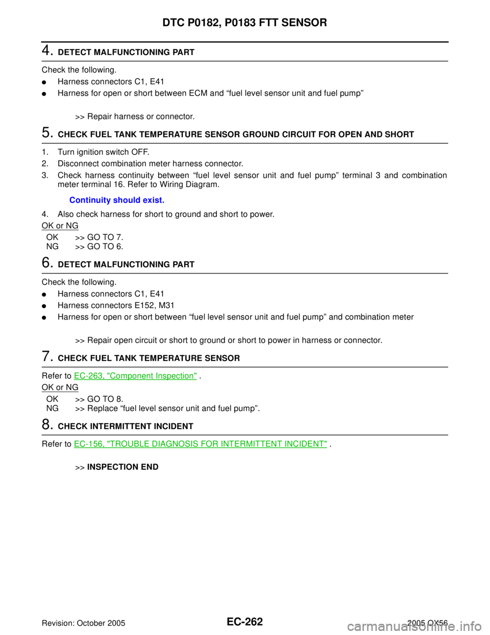
Voltage: Approximately 5V
PBIB0932E
Page 1453 of 3419

EC-262Revision: October 2005
DTC P0182, P0183 FTT SENSOR
2005 QX56
4. DETECT MALFUNCTIONING PART
Check the following.
�Harness connectors C1, E41
�Harness for open or short between ECM and “fuel level sensor unit and fuel pump”
>> Repair harness or connector.
5. CHECK FUEL TANK TEMPERATURE SENSOR GROUND CIRCUIT FOR OPEN AND SHORT
1. Turn ignition switch OFF.
2. Disconnect combination meter harness connector.
3. Check harness continuity between “fuel level sensor unit and fuel pump” terminal 3 and combination
meter terminal 16. Refer to Wiring Diagram.
4. Also check harness for short to ground and short to power.
OK or NG
OK >> GO TO 7.
NG >> GO TO 6.
6. DETECT MALFUNCTIONING PART
Check the following.
�Harness connectors C1, E41
�Harness connectors E152, M31
�Harness for open or short between “fuel level sensor unit and fuel pump” and combination meter
>> Repair open circuit or short to ground or short to power in harness or connector.
7. CHECK FUEL TANK TEMPERATURE SENSOR
Refer to EC-263, "
Component Inspection" .
OK or NG
OK >> GO TO 8.
NG >> Replace “fuel level sensor unit and fuel pump”.
8. CHECK INTERMITTENT INCIDENT
Refer to EC-156, "
TROUBLE DIAGNOSIS FOR INTERMITTENT INCIDENT" .
>>INSPECTION END Continuity should exist.
Page 1454 of 3419
DTC P0182, P0183 FTT SENSOR
EC-263
C
D
E
F
G
H
I
J
K
L
MA
EC
Revision: October 20052005 QX56
Component InspectionUBS00H3G
FUEL TANK TEMPERATURE SENSOR
1. Remove fuel level sensor unit.
2. Check resistance between “fuel level sensor unit and fuel pump”
terminals 3 and 4 by heating with hot water or heat gun as
shown in the figure.
Removal and InstallationUBS00H3H
FUEL TANK TEMPERATURE SENSOR
Refer to FL-5, "FUEL LEVEL SENSOR UNIT, FUEL FILTER AND FUEL PUMP ASSEMBLY" .
Temperature °C (°F) Resistance kΩ
20 (68) 2.3 - 2.7
50 (122) 0.79 - 0.90
SEF 4 76 YA
Page 1465 of 3419

EC-274Revision: October 2005
DTC P0300 - P0308 MULTIPLE CYLINDER MISFIRE, NO. 1 - 8 CYLINDER MIS-
FIRE
2005 QX56
5. CHECK FUNCTION OF IGNITION COIL-I
CAUTION:
Do the following procedure in the place where ventilation is good without the combustible.
1. Turn ignition switch OFF.
2. Remove fuel pump fuse in IPDM E/R to release fuel pressure.
NOTE:
Do not use CONSULT-II to release fuel pressure, or fuel pres-
sure applies again during the following procedure.
3. Start engine.
4. After engine stalls, crank it two or three times to release all fuel
pressure.
5. Turn ignition switch OFF.
6. Remove all ignition coil harness connectors to avoid the electri-
cal discharge from the ignition coils.
7. Remove ignition coil and spark plug of the cylinder to be
checked.
8. Crank engine for 5 seconds or more to remove combustion gas in the cylinder.
9. Connect spark plug and harness connector to ignition coil.
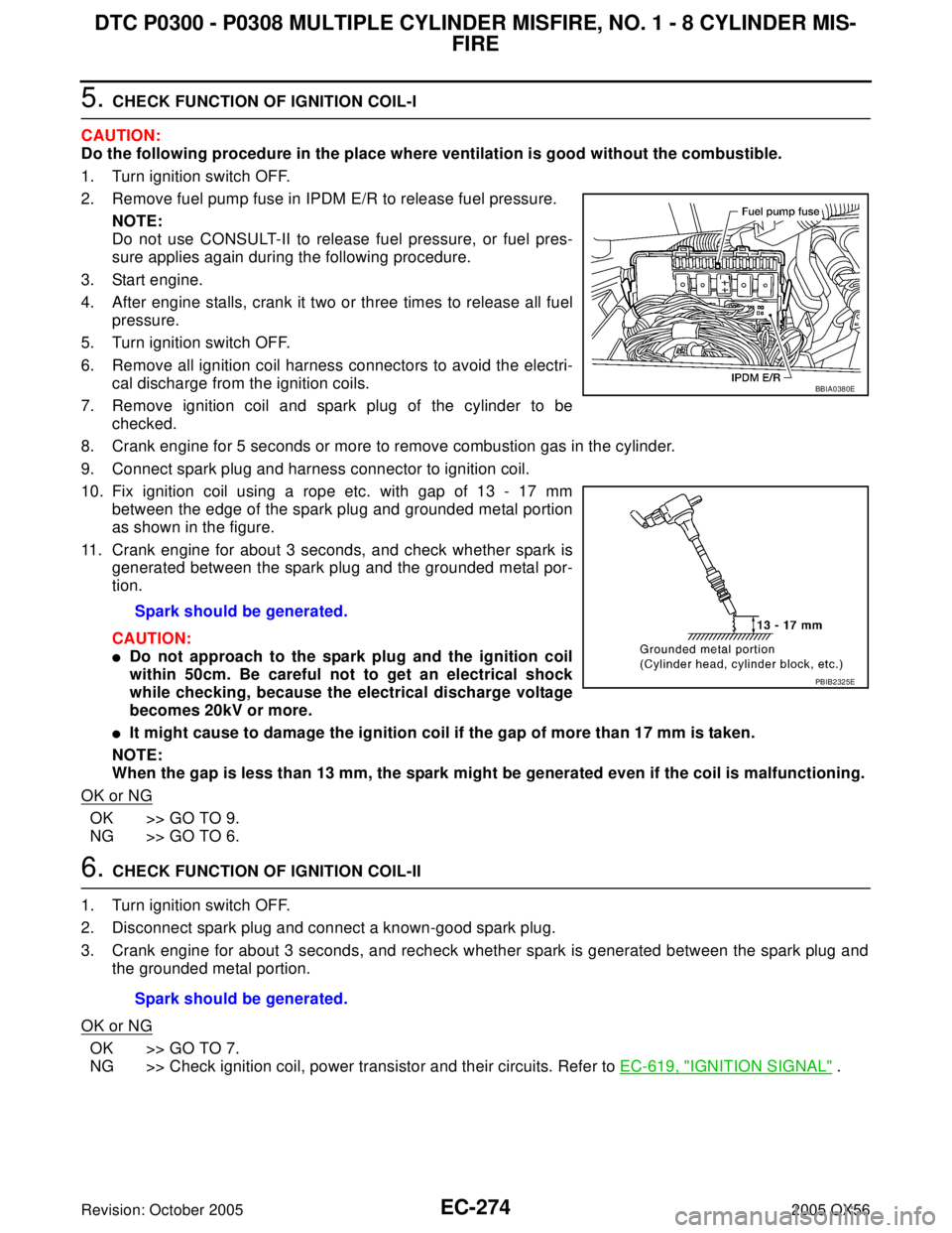
10. Fix ignition coil using a rope etc. with gap of 13 - 17 mm
between the edge of the spark plug and grounded metal portion
as shown in the figure.
11. Crank engine for about 3 seconds, and check whether spark is
generated between the spark plug and the grounded metal por-
tion.
CAUTION:
�Do not approach to the spark plug and the ignition coil
within 50cm. Be careful not to get an electrical shock
while checking, because the electrical discharge voltage
becomes 20kV or more.
�It might cause to damage the ignition coil if the gap of more than 17 mm is taken.
NOTE:
When the gap is less than 13 mm, the spark might be generated even if the coil is malfunctioning.
OK or NG
OK >> GO TO 9.
NG >> GO TO 6.
6. CHECK FUNCTION OF IGNITION COIL-II
1. Turn ignition switch OFF.
2. Disconnect spark plug and connect a known-good spark plug.
3. Crank engine for about 3 seconds, and recheck whether spark is generated between the spark plug and
the grounded metal portion.
OK or NG
OK >> GO TO 7.
NG >> Check ignition coil, power transistor and their circuits. Refer to EC-619, "
IGNITION SIGNAL" . Spark should be generated.
BBIA0380E
PBIB2325E
Spark should be generated.
Page 1466 of 3419

DTC P0300 - P0308 MULTIPLE CYLINDER MISFIRE, NO. 1 - 8 CYLINDER MIS-
FIRE
EC-275
C
D
E
F
G
H
I
J
K
L
MA
EC
Revision: October 20052005 QX56
7. CHECK SPARK PLUG
Check the initial spark plug for fouling, etc.
OK or NG
OK >> Replace spark plug(s) with standard type one(s). For
spark plug type, refer to EM-27, "
SPARK PLUG (PLATI-
NUM-TIPPED TYPE)" .
NG >> 1. Repair or clean spark plug.
2. GO TO 8.
8. CHECK FUNCTION OF IGNITION COIL-III
1. Reconnect the initial spark plugs.
2. Crank engine for about 3 seconds, and recheck whether spark is generated between the spark plug and
the grounded portion.
OK or NG
OK >>INSPECTION END
NG >> Replace spark plug(s) with standard type one(s). For spark plug type, refer to MA-18, "
Changing
Spark Plugs" .
9. CHECK COMPRESSION PRESSURE
Check compression pressure. Refer to EM-58, "
CHECKING COMPRESSION PRESSURE" .
OK or NG
OK >> GO TO 10.
NG >> Check pistons, piston rings, valves, valve seats and cylinder head gaskets.
10. CHECK FUEL PRESSURE
1. Install all removed parts.
2. Release fuel pressure to zero. Refer to EC-93, "
FUEL PRESSURE RELEASE" .
3. Install fuel pressure gauge and check fuel pressure. Refer to EC-94, "
FUEL PRESSURE CHECK" .
OK or NG
OK >> GO TO 12.
NG >> GO TO 11.
11 . DETECT MALFUNCTIONING PART
Check the following.
�Fuel pump and circuit (Refer to EC-637, "FUEL PUMP CIRCUIT" .)
�Fuel pressure regulator (Refer to EC-94, "FUEL PRESSURE CHECK" .)
�Fuel lines
�Fuel filter for clogging
>> Repair or replace.
SEF 1 56 I
Spark should be generated.
At idle: Approximately 350 kPa (3.57 kg/cm
2 , 51 psi)