Page 1716 of 3419
DTC P1279, P1289 A/F SENSOR 1
EC-525
C
D
E
F
G
H
I
J
K
L
MA
EC
Revision: October 20052005 QX56
Specification data are reference values and are measured between each terminal and ground.
CAUTION:
Do not use ECM ground terminals when measuring input/output voltage. Doing so may result in dam-
age to the ECM's transistor. Use a ground other than ECM terminals, such as the ground.
Diagnostic ProcedureUBS00HAR
1. CHECK GROUND CONNECTIONS
1. Turn ignition switch OFF.
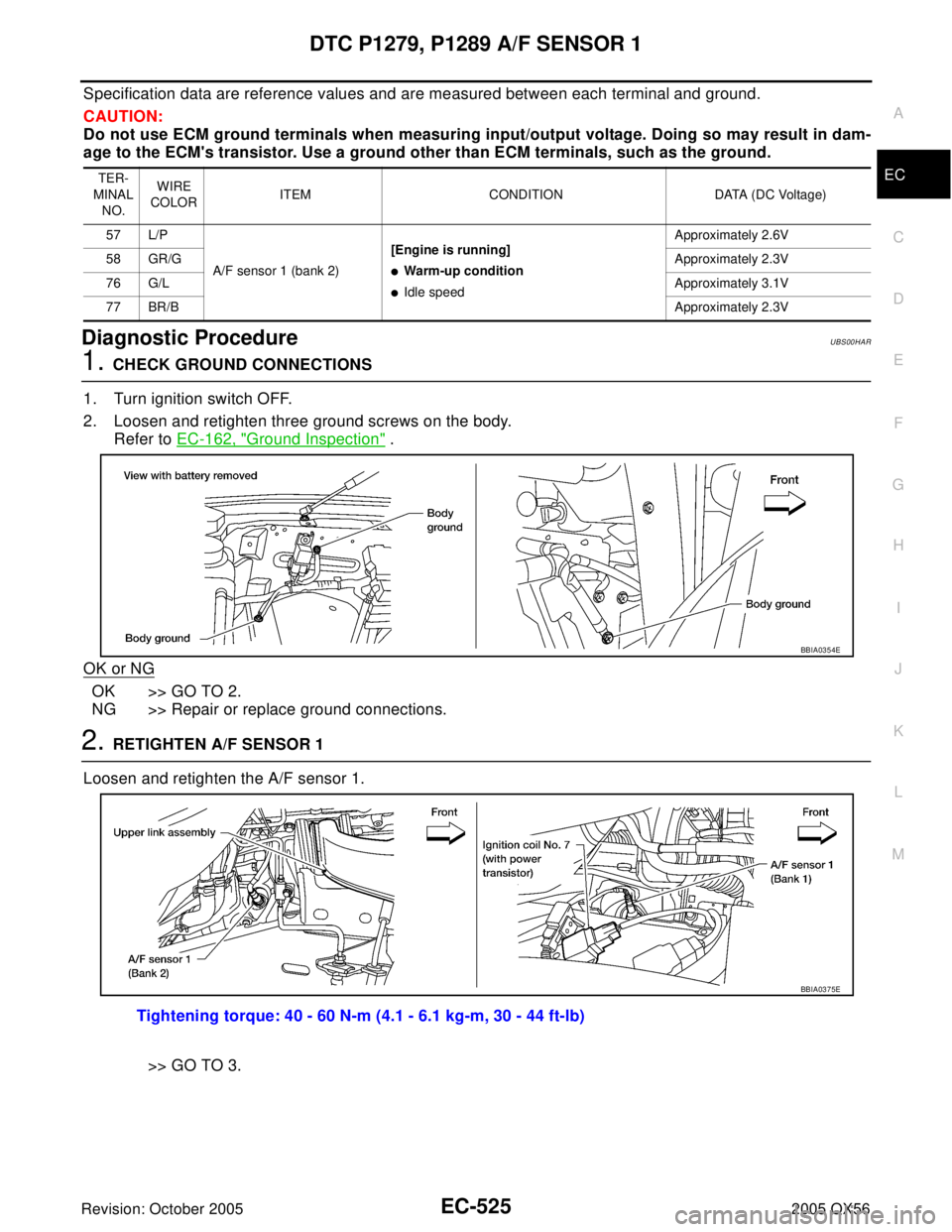
2. Loosen and retighten three ground screws on the body.
Refer to EC-162, "
Ground Inspection" .
OK or NG
OK >> GO TO 2.
NG >> Repair or replace ground connections.
2. RETIGHTEN A/F SENSOR 1
Loosen and retighten the A/F sensor 1.
>> GO TO 3.
TER-
MINAL
NO.WIRE
COLORITEM CONDITION DATA (DC Voltage)
57 L/P
A/F sensor 1 (bank 2)[Engine is running]
�Warm-up condition
�Idle speedApproximately 2.6V
58 GR/GApproximately 2.3V
76 G/LApproximately 3.1V
77 BR/BApproximately 2.3V
BBIA0354E
Tightening torque: 40 - 60 N-m (4.1 - 6.1 kg-m, 30 - 44 ft-lb)
BBIA0375E
Page 1722 of 3419
DTC P1444 EVAP CANISTER PURGE VOLUME CONTROL SOLENOID VALVE
EC-531
C
D
E
F
G
H
I
J
K
L
MA
EC
Revision: October 20052005 QX56
DTC P1444 EVAP CANISTER PURGE VOLUME CONTROL SOLENOID VALVE
PFP:14920
DescriptionUBS00HAT
SYSTEM DESCRIPTION
*1: ECM determines the start signal status by the signals of engine speed and battery voltage.
*2: This signal is sent to the ECM through CAN communication line.
This system controls flow rate of fuel vapor from the EVAP canister. The opening of the vapor by-pass pas-
sage in the EVAP canister purge volume control solenoid valve changes to control the flow rate. The EVAP
canister purge volume control solenoid valve repeats ON/OFF operation according to the signal sent from the
ECM. The opening of the valve varies for optimum engine control. The optimum value stored in the ECM is
determined by considering various engine conditions. When the engine is operating, the flow rate of fuel vapor
from the EVAP canister is regulated as the air flow changes.
COMPONENT DESCRIPTION
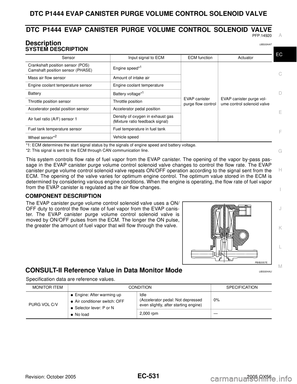
The EVAP canister purge volume control solenoid valve uses a ON/
OFF duty to control the flow rate of fuel vapor from the EVAP canis-
ter. The EVAP canister purge volume control solenoid valve is
moved by ON/OFF pulses from the ECM. The longer the ON pulse,
the greater the amount of fuel vapor that will flow through the valve.
CONSULT-II Reference Value in Data Monitor ModeUBS00HAU
Specification data are reference values.
Sensor Input signal to ECM ECM function Actuator
Crankshaft position sensor (POS)
Camshaft position sensor (PHASE)Engine speed*
1
EVAP canister
purge flow controlEVAP canister purge vol-
ume control solenoid valve Mass air flow sensor Amount of intake air
Engine coolant temperature sensor Engine coolant temperature
Battery
Battery voltage*
1
Throttle position sensor Throttle position
Accelerator pedal position sensor Accelerator pedal position
Air fuel ratio (A/F) sensor 1Density of oxygen in exhaust gas
(Mixture ratio feedback signal)
Fuel tank temperature sensor Fuel temperature in fuel tank
Wheel sensor*
2Vehicle speed
PBIB2057E
MONITOR ITEM CONDITION SPECIFICATION
PURG VOL C/V
�Engine: After warming up
�Air conditioner switch: OFF
�Selector lever: P or N
�No loadIdle
(Accelerator pedal: Not depressed
even slightly, after starting engine)0%
2,000 rpm —
Page 1729 of 3419
EC-538Revision: October 2005
DTC P1444 EVAP CANISTER PURGE VOLUME CONTROL SOLENOID VALVE
2005 QX56
Component InspectionUBS00HAZ
EVAP CANISTER PURGE VOLUME CONTROL SOLENOID VALVE
With CONSULT-II
Check air passage continuity of EVAP canister purge volume control
solenoid valve under the following conditions.
Without CONSULT-II
Check air passage continuity of EVAP canister purge volume control
solenoid valve under the following conditions.
Removal and InstallationUBS00HB0
EVAP CANISTER PURGE VOLUME CONTROL SOLENOID VALVE
Refer to EM-15, "INTAKE MANIFOLD" .
Condition
(PURG VOL CONT/V value)Air passage continuity
between A and B
100% Yes
0% No
PBIB2058E
ConditionAir passage continuity
between A and B
12V direct current supply between
terminals 1 and 2Ye s
No supply No
PBIB2059E
Page 1733 of 3419
EC-542Revision: October 2005
DTC P1446 EVAP CANISTER VENT CONTROL VALVE
2005 QX56
Specification data are reference values and are measured between each terminal and ground.
CAUTION:
Do not use ECM ground terminals when measuring input/output voltage. Doing so may result in dam-
age to the ECM's transistor. Use a ground other than ECM terminals, such as the ground.
Diagnostic ProcedureUBS00HB6
1. CHECK RUBBER TUBE
1. Turn ignition switch OFF.
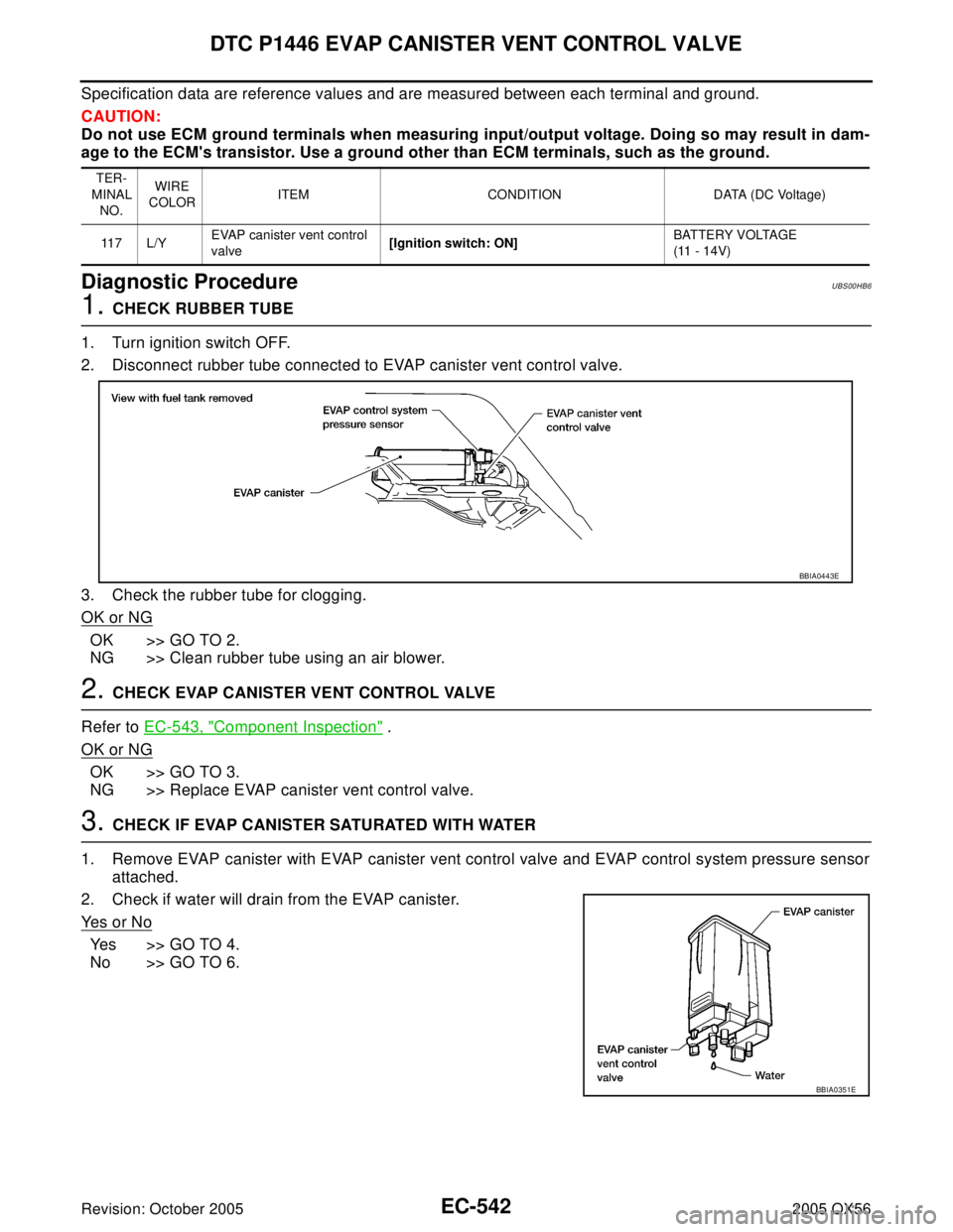
2. Disconnect rubber tube connected to EVAP canister vent control valve.
3. Check the rubber tube for clogging.
OK or NG
OK >> GO TO 2.
NG >> Clean rubber tube using an air blower.
2. CHECK EVAP CANISTER VENT CONTROL VALVE
Refer to EC-543, "
Component Inspection" .
OK or NG
OK >> GO TO 3.
NG >> Replace EVAP canister vent control valve.
3. CHECK IF EVAP CANISTER SATURATED WITH WATER
1. Remove EVAP canister with EVAP canister vent control valve and EVAP control system pressure sensor
attached.
2. Check if water will drain from the EVAP canister.
Ye s o r N o
Yes >> GO TO 4.
No >> GO TO 6.
TER-
MINAL
NO.WIRE
COLORITEM CONDITION DATA (DC Voltage)
11 7 L / YEVAP canister vent control
valve[Ignition switch: ON]BATTERY VOLTAGE
(11 - 14V)
BBIA0443E
BBIA0351E
Page 1735 of 3419
EC-544Revision: October 2005
DTC P1446 EVAP CANISTER VENT CONTROL VALVE
2005 QX56
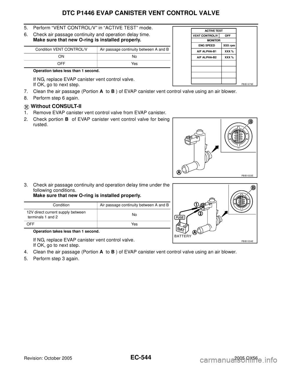
5. Perform “VENT CONTROL/V” in “ACTIVE TEST” mode.
6. Check air passage continuity and operation delay time.
Make sure that new O-ring is installed properly.
Operation takes less than 1 second.
If NG, replace EVAP canister vent control valve.
If OK, go to next step.
7. Clean the air passage (Portion A to B ) of EVAP canister vent control valve using an air blower.
8. Perform step 6 again.
Without CONSULT-II
1. Remove EVAP canister vent control valve from EVAP canister.
2. Check portion B of EVAP canister vent control valve for being
rusted.
3. Check air passage continuity and operation delay time under the
following conditions.
Make sure that new O-ring is installed properly.
Operation takes less than 1 second.
If NG, replace EVAP canister vent control valve.
If OK, go to next step.
4. Clean the air passage (Portion A to B ) of EVAP canister vent control valve using an air blower.
5. Perform step 3 again.
Condition VENT CONTROL/V Air passage continuity between A and B
ON No
OFF Yes
PBIB1679E
PBIB1033E
Condition Air passage continuity between A and B
12V direct current supply between
terminals 1 and 2No
OFF Yes
PBIB1034E
Page 1739 of 3419
EC-548Revision: October 2005
DTC P1564 ICC STEERING SWITCH
2005 QX56
Specification data are reference values and are measured between each terminal and ground.
CAUTION:
Do not use ECM ground terminals when measuring input/output voltage. Doing so may result in dam-
age to the ECM's transistor. Use a ground other than ECM terminals, such as the ground.
Diagnostic ProcedureUBS00L1R
1. CHECK GROUND CONNECTIONS
1. Turn ignition switch OFF.
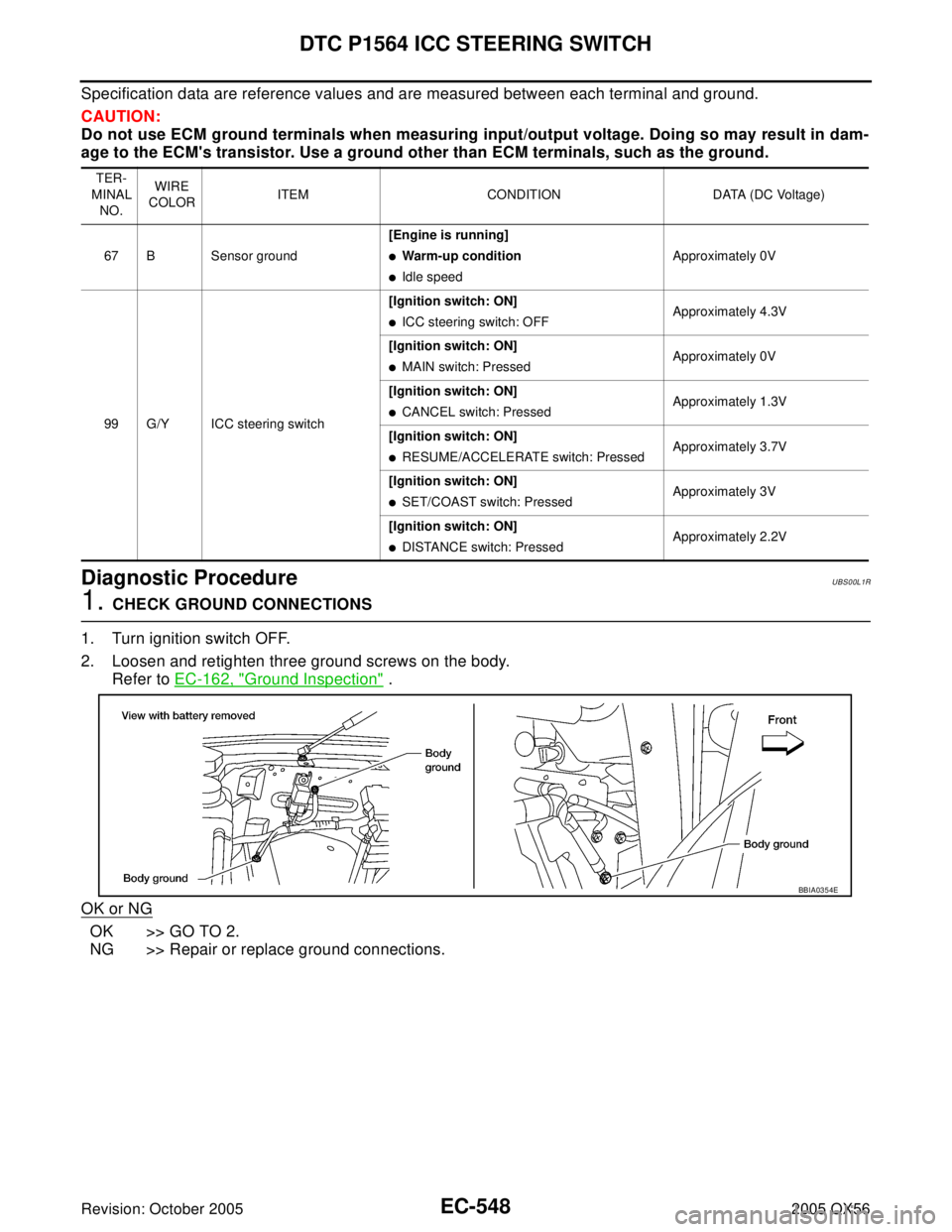
2. Loosen and retighten three ground screws on the body.
Refer to EC-162, "
Ground Inspection" .
OK or NG
OK >> GO TO 2.
NG >> Repair or replace ground connections.
TER-
MINAL
NO.WIRE
COLORITEM CONDITION DATA (DC Voltage)
67 B Sensor ground[Engine is running]
�Warm-up condition
�Idle speedApproximately 0V
99 G/Y ICC steering switch[Ignition switch: ON]
�ICC steering switch: OFFApproximately 4.3V
[Ignition switch: ON]
�MAIN switch: PressedApproximately 0V
[Ignition switch: ON]
�CANCEL switch: PressedApproximately 1.3V
[Ignition switch: ON]
�RESUME/ACCELERATE switch: PressedApproximately 3.7V
[Ignition switch: ON]
�SET/COAST switch: PressedApproximately 3V
[Ignition switch: ON]
�DISTANCE switch: PressedApproximately 2.2V
BBIA0354E
Page 1746 of 3419
DTC P1564 ASCD STEERING SWITCH
EC-555
C
D
E
F
G
H
I
J
K
L
MA
EC
Revision: October 20052005 QX56
Specification data are reference values and are measured between each terminal and ground.
CAUTION:
Do not use ECM ground terminals when measuring input/output voltage. Doing so may result in dam-
age to the ECM's transistor. Use a ground other than ECM terminals, such as the ground.
Diagnostic ProcedureUBS00L11
1. CHECK GROUND CONNECTIONS
1. Turn ignition switch OFF.
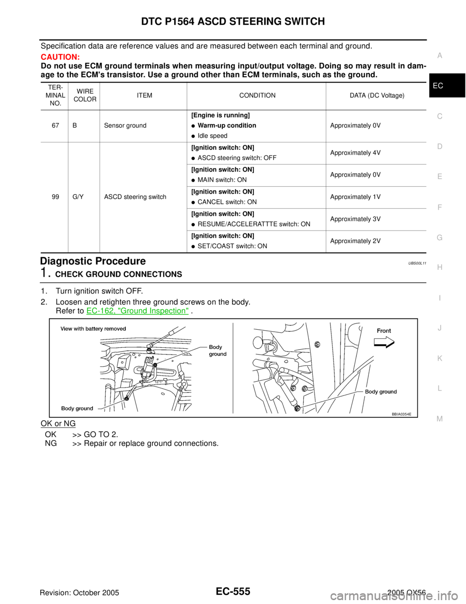
2. Loosen and retighten three ground screws on the body.
Refer to EC-162, "
Ground Inspection" .
OK or NG
OK >> GO TO 2.
NG >> Repair or replace ground connections.
TER-
MINAL
NO.WIRE
COLORITEM CONDITION DATA (DC Voltage)
67 B Sensor ground[Engine is running]
�Warm-up condition
�Idle speedApproximately 0V
99 G/Y ASCD steering switch[Ignition switch: ON]
�ASCD steering switch: OFFApproximately 4V
[Ignition switch: ON]
�MAIN switch: ONApproximately 0V
[Ignition switch: ON]
�CANCEL switch: ONApproximately 1V
[Ignition switch: ON]
�RESUME/ACCELERATTTE switch: ONApproximately 3V
[Ignition switch: ON]
�SET/COAST switch: ONApproximately 2V
BBIA0354E
Page 1755 of 3419
EC-564Revision: October 2005
DTC P1572 ICC BRAKE SWITCH
2005 QX56
2. CHECK OVERALL FUNCTION-II
With CONSULT-II
Check “BRAKE SW2” indication in “DATA MONITOR” mode.
Without CONSULT-II
Check voltage between ECM terminal 101 and ground under the fol-
lowing conditions.
OK or NG
OK >> GO TO 14.
NG >> GO TO 10.
3. CHECK DTC WITH ICC UNIT
Refer to EC-156, "
TROUBLE DIAGNOSIS FOR INTERMITTENT INCIDENT" .
OK or NG
OK >> GO TO 4.
NG >> Repair or replace.
CONDITION INDICATION
Brake pedal: Fully released OFF
Brake pedal: Slightly depressed ON
SEC0 13 D
CONDITION VOLTAGE
Brake pedal: Fully released Approximately 0V
Brake pedal: Slightly depressed Battery voltage
PBIB1537E