Page 2827 of 3419
RF-10
SUNROOF
Revision: October 20052005 QX56
SUNROOFPFP:91210
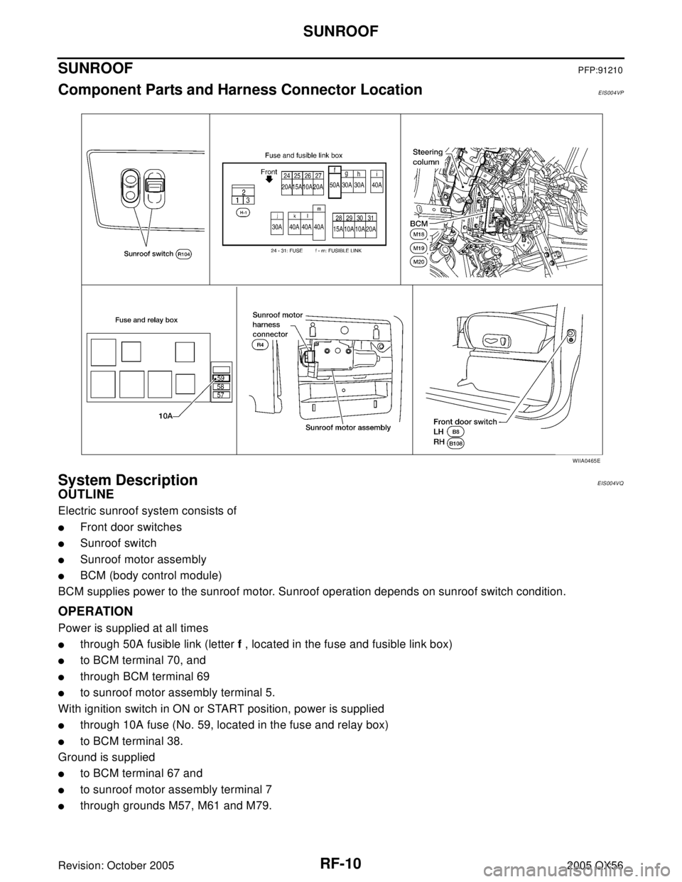
Component Parts and Harness Connector LocationEIS004VP
System DescriptionEIS004VQ
OUTLINE
Electric sunroof system consists of
�Front door switches
�Sunroof switch
�Sunroof motor assembly
�BCM (body control module)
BCM supplies power to the sunroof motor. Sunroof operation depends on sunroof switch condition.
OPERATION
Power is supplied at all times
�through 50A fusible link (letter f , located in the fuse and fusible link box)
�to BCM terminal 70, and
�through BCM terminal 69
�to sunroof motor assembly terminal 5.
With ignition switch in ON or START position, power is supplied
�through 10A fuse (No. 59, located in the fuse and relay box)
�to BCM terminal 38.
Ground is supplied
�to BCM terminal 67 and
�to sunroof motor assembly terminal 7
�through grounds M57, M61 and M79.
WIIA0465E
Page 2835 of 3419

RF-18
SUNROOF
Revision: October 20052005 QX56
BCM Power Supply and Ground Circuit CheckEIS004W1
1. CHECK FUSE
Check the following BCM fuse and fusible link.
NOTE:
Refer to RF-10, "
Component Parts and Harness Connector Location" .
OK or NG
OK >> GO TO 2.
NG >> If fuse is blown, be sure to eliminate cause of blown fuse before installing new fuse. Refer to PG-
4, "POWER SUPPLY ROUTING CIRCUIT" .
2. CHECK POWER SUPPLY CIRCUIT
1. Turn ignition switch OFF.
2. Disconnect BCM connectors.
3. Check voltage between BCM connectors M18 and M20 termi-
nals 38, 70 and ground.
OK or NG
OK >> GO TO 3.
NG >> Repair or replace harness.
3. CHECK GROUND CIRCUIT
Check continuity between BCM connector M20 terminal 67 and
ground.
OK or NG
OK >> Power supply and ground circuit is OK.
NG >> Repair or replace harness.
Retained power operation does not operate properly.1. Check the retained power operation mode settingRF-112. BCM power supply and ground circuit checkRF-18
3. Door switch checkRF-21
4. Replace sunroof motor assemblyRF-27
Motor does not stop at the sunroof fully-open or fully-
closed position.1. Initialization procedure checkRF-11
2. Replace sunroof motor assemblyRF-27
Sunroof does not do the interruption detection. 1. Replace sunroof motor assemblyRF-27
Symptom Diagnostic procedure and repair order Refer to page
Component Parts Terminal No. (SIGNAL) Ampere No. Location
BCM38 (IGN power supply) 10A 59 Fuse and relay box
70 (BAT power supply) 50A f Fuse and fusible link box
ConnectorTerminals
(Wire color)
ConditionVo l ta g e
(Approx.)
(+) (–)
M18 38 (W/L)
GroundIgnition switch ON
Battery voltage
M20 70 (W/B) Igniting switch OFF
WIIA0229E
Connector Terminals (Wire color) Continuity
M20 67 (B) Ground YES
LIIA0915E
Page 2976 of 3419
AUTOMATIC DRIVE POSITIONER
SE-11
C
D
E
F
G
H
J
K
L
MA
B
SE
Revision: October 20052005 QX56
AUTOMATIC DRIVE POSITIONERPFP:28491
Component Parts And Harness Connector LocationEIS0058U
1. Fuse block (J/B) 2. Fuse and relay box 3. Fuse and fusible link box
4. A. Automatic drive positioner control
unit M33, M34
B. Pedal adjusting motor E109,
E1105. A. Steering column
B. Key switch and key lock solenoid
M27
C. BCM M18, M19, M20 (view with
instrument panel removed)6. A. Door mirror remote control switch
D10
B. Seat memory switch D5
LIIA2361E
Page 3226 of 3419

2. Disconnect tra")
TROUBLE DIAGNOSIS FOR SYSTEM
TF-83
C
E
F
G
H
I
J
K
L
MA
B
TF
Revision: October 20052005 QX56
2. CHECK GROUND CIRCUIT
1. Turn ignition switch “OFF”. (Stay for at least 5 seconds.)
2. Disconnect transfer control unit harness connector.
3. Check continuity between transfer control unit harness connec-
tor E142 terminals 3 (B), 6 (B), E143 terminal 45 (B) and ground.
Also check harness for short to ground and short to power.
OK or NG
OK >> GO TO 3.
NG >> Repair open circuit or short to ground or short to power
in harness or connectors.
3. CHECK ACTUATOR MOTOR POWER SUPPLY CIRCUIT
1. Turn ignition switch “OFF”. (Stay for at least 5 seconds.)
2. Remove transfer shift high relay and transfer shift low relay. Refer to TF-22, "
Location of Electrical Parts" .
3. Check voltage between transfer shift high relay harness connec-
tor E46 terminal 5 (R), transfer shift low relay harness connector
E47 terminal 5 (R) and ground.
4. Turn ignition switch “ON”. (Do not start engine.)
5. Check voltage between transfer shift high relay harness connec-
tor E46 terminal 5 (R), transfer shift low relay harness connector
E47 terminal 5 (R) and ground.
OK or NG
OK >> GO TO 4.
NG >> Check the following. If any items are damaged, repair or
replace damaged parts.
�20A fuse No. 57 located in the fuse and relay box. Refer to PG-4, "POWER SUPPLY ROUTING
CIRCUIT" .
�Harness for short or open between battery, transfer shift high relay harness connector E46 ter-
minal 5 (R) and transfer shift low relay harness connector E47 terminal 5 (R). Continuity should exist.
SDIA2691E
Connector Terminal (Wire color) Voltage (Approx.)
E46 5 (R) - Ground
Battery voltage
E47 5 (R) - Ground
SDIA2707E
Connector Terminal (Wire color) Voltage (Approx.)
E46 5 (R) - Ground
Battery voltage
E47 5 (R) - Ground
SDIA2706E
Page 3242 of 3419

TROUBLE DIAGNOSIS FOR SYSTEM
TF-99
C
E
F
G
H
I
J
K
L
MA
B
TF
Revision: October 20052005 QX56
2. CHECK TRANSFER MOTOR RELAY POWER SUPPLY CIRCUIT
1. Turn ignition switch “OFF”. (Stay for at least 5 seconds.)
2. Connect transfer control unit harness connector.
3. Disconnect transfer motor relay.
4. Check voltage between transfer motor relay harness connector
terminals and ground.
5. Turn ignition switch “ON”. (Do not start engine.)
6. Check voltage between transfer motor relay harness connector
terminals and ground.
OK or NG
OK >> GO TO 3.
NG >> Check the following. If any items are damaged, repair or
replace damaged parts.
�20A fuse No. 58 located in the fuse and relay box. Refer to PG-4, "POWER SUPPLY ROUTING
CIRCUIT" .
�10A fuse No. 26 located in the fuse and fusible link box. Refer to PG-4, "POWER SUPPLY
ROUTING CIRCUIT"
�Harness for short or open between battery and transfer motor relay harness connector E154
terminal 5 (G/R).
�Harness for short or open between transfer shut off relay harness connector E69 terminal 5 (Y/
R) and transfer motor relay harness connector E153 terminal 2 (Y/R).
�Battery and ignition switch. Refer to PG-4, "POWER SUPPLY ROUTING CIRCUIT" .
3. CHECK TRANSFER MOTOR RELAY
1. Turn ignition switch “OFF”.
2. Remove transfer motor relay. Refer to TF-22, "
Location of Electrical Parts" .
3. Apply 12V direct current between transfer motor relay terminals
1 and 2.
4. Check continuity between relay terminals 3 and 5.
OK or NG
OK >> GO TO 4.
NG >> Replace the transfer motor relay.
Connector Terminal (Wire color) Voltage (Approx.)
E153 2 (Y/R) - Ground 0V
E154 5 (G/R) - Ground Battery voltage
WDIA0169E
Connector Terminal (Wire color) Voltage (Approx.)
E153 2 (Y/R) - Ground
Battery voltage
E154 5 (G/R) - Ground
WDIA0170E
Condition Continuity
12V direct current supply between terminals 1 and 2 Yes
OFF No
LDIA0098E
Page 3363 of 3419

WW-4
FRONT WIPER AND WASHER SYSTEM
Revision: October 20052005 QX56
FRONT WIPER AND WASHER SYSTEMPFP:28810
Components Parts and Harness Connector LocationEKS00BDS
System DescriptionEKS00BDT
�Both front wiper relays are located in the IPDM E/R (intelligent power distribution module engine room).
�The wiper switch (combination switch) is composed of a combination of 5 output terminals and 5 input ter-
minals. Terminal combination status is read by the BCM when the wiper switch is turned ON.
�BCM controls front wiper LO, HI, and INT (intermittent) operation.
�IPDM E/R (intelligent power distribution module engine room) operates the wiper motor according to CAN
communication signals from the BCM.
Power is supplied at all times
�through 50A fusible link (letter f , located in the fuse and fusible link box)
�to BCM terminal 70, and
�through 30A fuse (No. 39, located in the IPDM E/R)
�to front wiper relay (located in the IPDM E/R).
With the ignition switch in ON or START position, power is supplied
�through 10A fuse (No. 9, located in the fuse block J/B)
WKIA1920E
Page 3394 of 3419
REAR WIPER AND WASHER SYSTEM
WW-35
C
D
E
F
G
H
I
J
L
MA
B
WW
Revision: October 20052005 QX56
REAR WIPER AND WASHER SYSTEMPFP:28710
Components Parts and Harness Connector LocationEKS00BEB
System DescriptionEKS00BEC
�The wiper switch (combination switch) is composed of a combination of 5 output terminals and 5 input ter-
minals. Terminal combination status is read by the BCM (body control module) when switch is turned ON.
�The BCM controls rear wiper ON and INT (intermittent) operation.
Power is supplied at all times
�through 50A fusible link (letter f , located in fusible link box)
�to BCM terminal 70.
With the ignition switch in ON or START position, power is supplied
�through 10A fuse [No. 9, located in fuse block (J/B)]
�to combination switch terminal 14, and
�through 10A fuse (No. 59, located in the fuse and relay box)
�to BCM terminal 38.
Ground is supplied
�to BCM terminal 67 and
�to combination switch terminal 12
�through grounds M57, M61 and M79.
WKIA3462E
Page:
< prev 1-8 9-16 17-24