Page 2029 of 3419

FAX-12
DRIVE SHAFT
Revision: October 20052005 QX56
4. Attach the circlip to the drive shaft. The circlip must fit securely
into the drive shaft groove. Attach the nut to the joint sub-assem-
bly.
Use a soft hammer to press-fit the circlip.
NOTE:
Discard the old circlip and use a new one for assembly.
5. Insert the specified quantity of Genuine NISSAN Grease or
equivalent, into the joint sub-assembly and the large end of the
boot. Refer to MA-11, "
RECOMMENDED FLUIDS AND LUBRI-
CANTS" .
6. Install the boot securely into the grooves (indicated by the *
marks) as shown.
CAUTION:
If there is grease on the boot mounting surfaces (indicated
by the * marks) of the drive shaft and joint sub-assembly,
the boot may come off. Remove all grease from the drive
shaft surfaces.
7. Check that the boot installation length “L” is the specified length.
Insert a suitable tool into the large end of the boot. Bleed the air
from the boot to prevent boot deformation.
CAUTION:
�The boot may break if the boot installation length is less than the specified length.
�Do not contact inside surface of boot with the tip of the screwdriver.
8. Secure large and small ends of the boot using new boot bands
using tool as shown.
NOTE:
Discard the old boot bands and use new ones for assembly.
�Secure boot band so that dimension "M" meets specification
as shown.
9. After installing the joint sub-assembly to the drive shaft, rotate the boot to check that it is positioned cor-
rectly. If the boot is not positioned correctly, reposition the boot and secure the boot using a new boot
band.Grease capacity : 145 − 165 g (5.11 − 5.82 oz)
RAC0049D
Boot installation length “L” : 168.4 mm (6.63 in)
Tool number : KV40107300 ( — )WDIA0288E
RAC1133D
Dimension "M" : 1.0 – 4.0 mm (0.39 – 1.57 in)
DSF0047D
Page 2030 of 3419
SERVICE DATA AND SPECIFICATIONS (SDS)
FAX-13
C
E
F
G
H
I
J
K
L
MA
B
FA X
Revision: October 20052005 QX56
SERVICE DATA AND SPECIFICATIONS (SDS)PFP:00030
Wheel BearingEDS001XH
Drive ShaftEDS001XI
Boot BandsEDS003M9
Unit: mm (in) Wheel bearing axial end play 0.05 mm (0.002 in) or less
Drive shaft joint typeFinal drive side Rzeppa
Wheel side Rzeppa
GreaseQualityNissan Genuine Grease or
equivalent
Capacity Final drive side 130 - 150 g (4.58 - 5.29 oz)
Wheel side 145 - 165 g (5.11 - 5.82 oz)
Boot length Final drive side "L " 145 mm (5.71 in)
Wheel side "L " 168.4 mm (6.63 in)
WDIA0055E
Dimension "M" 1.0 - 4.0 (0.39 - 1.57)
DSF0047D
Page 2097 of 3419

FSU-18
KNUCKLE
Revision: October 20052005 QX56
7. Disconnect steering outer socket from steering knuckle using
Tool. Be careful not to damage ball joint boot.
CAUTION:
To prevent damage to threads and to prevent Tool from
coming off suddenly, temporarily install mounting nut
loosely.
8. Remove drive shaft, if equipped. Refer to FAX-7, "
Removal and Installation" .
9. Remove wheel hub and bearing assembly bolts using power tool.
10. Remove splash guard and wheel hub and bearing assembly from steering knuckle.
11. Support lower link using a suitable jack.
12. Remove cotter pin and nut from upper link ball joint.
13. Separate upper link ball joint from steering knuckle using Tool.
14. Remove pinch bolt from steering knuckle using power tool. Then
remove steering knuckle from lower link ball joint.
15. Remove steering knuckle from vehicle.
INSPECTION AFTER REMOVAL
Check for deformity, cracks and damage on each part, replace if necessary.
�Perform ball joint inspection. Refer to FSU-15, "Inspection" .
SGIA0488E
Tool number : ST29020001 (J-24319-01)
LEIA0095E
LEIA0097E
Page 2111 of 3419
GI-10
HOW TO USE THIS MANUAL
Revision: October 20052005 QX56
SYMBOLS
1. Union bolt 2. Copper washer 3. Brake hose
4. Cap 5. Bleed valve 6. Sliding pin bolt
7. Piston seal 8. Piston 9. Piston boot
10. Cylinder body 11. Sliding pin 12. Torque member mounting bolt
13. Washer 14. Sliding pin boot 15. Bushing
16. Torque member 17. Inner shim cover 18. Inner shim
19. Inner pad 20. Pad retainer 21. Pad wear sensor
22. Outer pad 23. Outer shim 24. Outer shim cover
1: PBC (Poly Butyl Cuprysil) grease
or silicone-based grease2: Rubber grease : Brake fluid
Refer to GI section for additional symbol definitions.
SFIA2959E
SAIA0749E
Page 2641 of 3419
 After 60,000 miles (96,000 km) or 48 months, inspect every 15,000 miles (24,000 km) or 12 months. Replace drive belts if damaged.
(2) If")
MA-8
PERIODIC MAINTENANCE
Revision: October 20052005 QX56
(1) After 60,000 miles (96,000 km) or 48 months, inspect every 15,000 miles (24,000 km) or 12 months. Replace drive belts if damaged.
(2) If operating mainly in dusty conditions, more frequent maintenance may be required.
(3) Maintenance-free item. For service procedures, go to the FL section.
(4) After 60,000 miles (96,000 km) or 48 months, replace every 30,000 miles (48,000 km) or 24 months.
(5) If valve noise increases, inspect valve clearance.
* Maintenance items and intervals with “*” are recommended by NISSAN for reliable vehicle operation. The owner need not perform
such maintenance in order to maintain the emission warranty or manufacturer recall liability. Other maintenance items and intervals are
required.
CHASSIS AND BODY MAINTENANCE
Abbreviations: R = Replace. I = Inspect. Correct or replace if necessary. L = Lubricate. [ ]: At the mileage intervals only. MAINTENANCE OPERATIONMAINTENANCE INTERVAL
Reference
Section -
Page or -
Content Title Perform at number of miles, kilo-
meters or months, whichever
comes first.Miles x 1,000
(km x 1,000)
Months33.75
(54)
2737.5
(60)
3041.25
(66)
3345
(72)
3648.75
(78)
3952.5
(84)
4256.25
(90)
4560
(96)
48
Drive belts NOTE (1) I*MA-13
Air cleaner filter NOTE (2) [R]MA-16
EVAP vapor linesI*MA-20
Fuel linesI*MA-16
Fuel filter NOTE (3)—
Engine coolant NOTE (4) R*MA-13
Engine oil R R R R R R R RMA-17
Engine oil filter R R R R R R R RMA-17
Spark plugs (double PLATINUM-
TIPPED type)Replace every 105,000 miles (169,000 km).MA-18
Intake and exhaust valve clear-
ance*NOTE (5)EM-51
MAINTENANCE OPERATIONMAINTENANCE INTERVAL
Reference
Section
- Page
or
- Content
Title Perform at number of miles, kilometers or
months, whichever comes first.Miles x
1,000
(km x
1,000)
Months3.75
(6)
37.5
(12)
611 . 2 5
(18)
915
(24)
1218.75
(30)
1522.5
(36)
1826.25
(42)
2130
(48)
24
Brake lines and cables I IMA-28
Brake pads and rotors I I I IMA-28
Automatic transmission fluid NOTE (1) I I MA-22
Transfer fluid and front final drive oil NOTE (1) I IMA-25,
MA-25
Rear final drive oil NOTE (1) I IMA-25,
MA-25
Steering gear, linkage, axle, and suspension
partsII I IMA-29,
MA-30
Tire Rotation NOTE (2)MA-28
Drive shaft boots and propeller shaft (4WD) I I I IMA-25
Exhaust system I I I IMA-22
In-cabin microfilter R RMA-21
Page 2642 of 3419
 If towing a trailer, or using a car-top carrier, or driving on rough or muddy roads, change (not just inspect) o")
PERIODIC MAINTENANCE
MA-9
C
D
E
F
G
H
I
J
K
MA
B
MA
Revision: October 20052005 QX56
(1) If towing a trailer, or using a car-top carrier, or driving on rough or muddy roads, change (not just inspect) oil at every 30,000 miles
(48,000 km) or 24 months.
(2) Refer to “Tire rotation” under the “General maintenance” heading earlier in this section.
Schedule 2ELS001BM
EMISSION CONTROL SYSTEM MAINTENANCE
Abbreviations: R = Replace. I = Inspect. Correct or replace if necessary. [ ]: At the mileage intervals only
(1) After 60,000 miles (96,000 km) or 48 months, inspect every 15,000 miles (24,000 km) or 12 months. Replace drive belts if damaged.
(2) Maintenance-free item. For service procedures, go to FL section.
(3) After 60,000 miles (96,000 km) or 48 months, replace every 30,000 miles (48,000 km) or 24 months.
(4) If valve noise increases, inspect valve clearance.
* Maintenance items and intervals with “*” are recommended by NISSAN for reliable vehicle operation. The owner need not perform
such maintenance in order to maintain the emission warranty or manufacturer recall liability. Other maintenance items and intervals are
required. MAINTENANCE OPERATIONMAINTENANCE INTERVAL
Reference
Section
- Page
or
- Content
Title Perform at number of miles, kilometers or
months, whichever comes first.Miles x
1,000
(km x
1,000)
Months33.75
(54)
2737.5
(60)
3041.25
(66)
3345
(72)
3648.75
(78)
3952.5
(84)
4256.25
(90)
4560
(96)
48
Brake lines and cables I IMA-28
Brake pads and rotors I I I IMA-28
Automatic transmission fluid NOTE (1) I IMA-22
Transfer fluid and front final drive oil NOTE (1) I IMA-25,
MA-25
Rear final drive oil NOTE (1) I IMA-25,
MA-25
Steering gear, linkage, axle, and suspension
partsIIIIMA-29,
MA-30
Tire Rotation NOTE (2)MA-28
Drive shaft boots and propeller shaft (4WD) I I I IMA-25
Exhaust system I I I IMA-22
In-cabin microfilter R RMA-21
MAINTENANCE OPERATIONMAINTENANCE INTERVAL
Reference
Section - Page
or - Content
Title Perform at number of miles, kilome-
ters or months, whichever comes first.Miles x 1,000
(km x 1,000)
Months7.5
(12)
615
(24)
1222.5
(36)
1830
(48)
2437.5
(60)
3045
(72)
3652.5
(84)
4260
(96)
48
Drive belts NOTE (1) I*MA-13
Air cleaner filter [R] [R]MA-16
EVAP vapor lines I* I*MA-20
Fuel lines I* I*MA-16
Fuel filter NOTE (2)—
Engine coolant NOTE (3) R*MA-13
Engine oil R R R R R R R RMA-17
Engine oil filter R R R R R R R RMA-17
Spark plugs (PLATINUM-TIPPED
type)Replace every 105,000 miles (169,000 km).MA-18
Intake and exhaust valve clearance* NOTE (4)EM-51
Page 2643 of 3419
![INFINITI QX4 2005 Factory Service Manual MA-10
PERIODIC MAINTENANCE
Revision: October 20052005 QX56
CHASSIS AND BODY MAINTENANCE
Abbreviations: R = Replace. I = Inspect. Correct or replace if necessary. L = Lubricate. [ ]: At the mileage int](/manual-img/42/57035/w960_57035-2642.png "INFINITI QX4 2005 Factory Service Manual MA-10
PERIODIC MAINTENANCE
Revision: October 20052005 QX56
CHASSIS AND BODY MAINTENANCE
Abbreviations: R = Replace. I = Inspect. Correct or replace if necessary. L = Lubricate. [ ]: At the mileage int")
MA-10
PERIODIC MAINTENANCE
Revision: October 20052005 QX56
CHASSIS AND BODY MAINTENANCE
Abbreviations: R = Replace. I = Inspect. Correct or replace if necessary. L = Lubricate. [ ]: At the mileage interval only.
(1) Refer to “Tire rotation” under the “General maintenance” heading earlier in this section.MAINTENANCE OPERATIONMAINTENANCE INTERVAL Reference
Section
- Page
or
- Content
Title Perform at number of miles, kilometers or
months, whichever comes first.Miles x 1,000
(km x 1,000)
Months7.5
(12)
615
(24)
1222.5
(36)
1830
(48)
2437.5
(60)
3045
(72)
3652.
5
(84)
4260
(96)
48
Brake lines and cables I I I IMA-28
Brake pads and rotors I I I IMA-28
Automatic transmission fluid I I I IMA-22
Transfer fluid and front final drive oil I I I IMA-25,
MA-25
Rear final drive oil I I I IMA-25,
MA-25
Steering gear, linkage, axle, and suspension
parts.IIMA-29,
MA-30
Tire rotation NOTE (1)MA-28
Drive shaft boots and propeller shaft
(4x4)IIIIMA-25
Exhaust systemIIMA-22
In-cabin microfilter R R R RMA-21
Page 2663 of 3419
MA-30
CHASSIS AND BODY MAINTENANCE
Revision: October 20052005 QX56
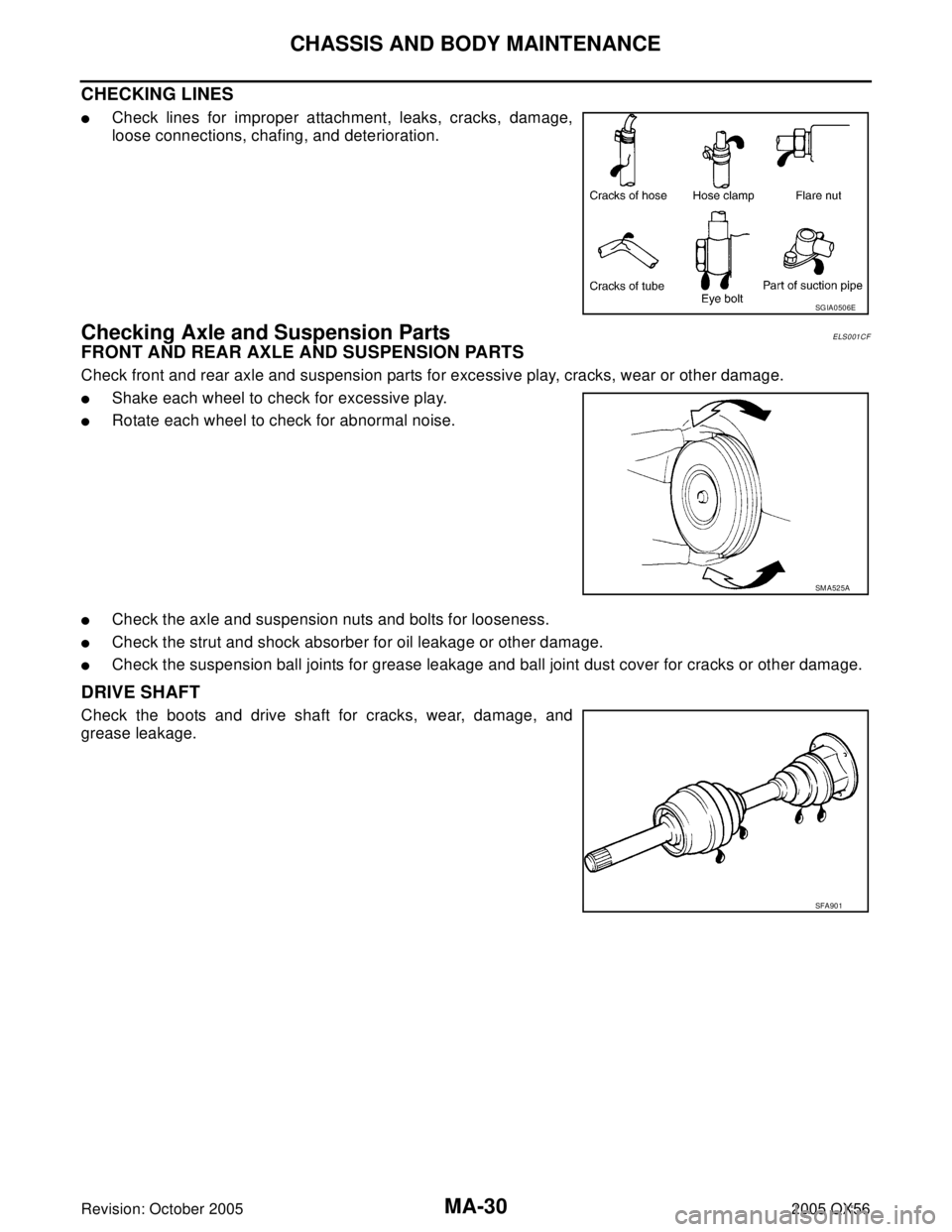
CHECKING LINES
�Check lines for improper attachment, leaks, cracks, damage,
loose connections, chafing, and deterioration.
Checking Axle and Suspension PartsELS001CF
FRONT AND REAR AXLE AND SUSPENSION PARTS
Check front and rear axle and suspension parts for excessive play, cracks, wear or other damage.
�Shake each wheel to check for excessive play.
�Rotate each wheel to check for abnormal noise.
�Check the axle and suspension nuts and bolts for looseness.
�Check the strut and shock absorber for oil leakage or other damage.
�Check the suspension ball joints for grease leakage and ball joint dust cover for cracks or other damage.
DRIVE SHAFT
Check the boots and drive shaft for cracks, wear, damage, and
grease leakage.
SGIA0506E
SM A52 5A
SFA90 1

FAX-13
C
E
F
G
H
I
J
K
L
MA
B
FA X
Revision: October 20052005 QX56
SERVICE DATA AND SPECIFICATIONS (SDS)PFP:00030
Wheel BearingEDS001XH
Drive ShaftEDS001XI
Boot B")