Page 3299 of 3419
TF-156
TRANSFER ASSEMBLY
Revision: October 20052005 QX56
21. Remove the snap ring from the mainshaft.
22. Remove the mainshaft from the clutch drum and clutch hub,
using suitable tool.
23. Remove the needle bearing and spacer from the mainshaft.
24. Remove the snap ring from the clutch hub, using suitable tool.
25. Remove the oil pressure check plug from the oil pressure check
port.
26. Apply air gradually from the oil pressure check port, and remove
the clutch piston assembly from the center case.
SDIA2 113 E
SMT914C
WDIA0101E
WDIA0227E
SDIA2 116 E
Page 3300 of 3419
TRANSFER ASSEMBLY
TF-157
C
E
F
G
H
I
J
K
L
MA
B
TF
Revision: October 20052005 QX56
27. Remove the thrust needle bearing race from the clutch piston by
hooking a edge into 3 notches of the thrust needle bearing race,
using suitable tool.
CAUTION:
Do not damage clutch piston or thrust needle bearing race.
28. Remove the two D-rings from the clutch piston.
29. Remove the mainshaft rear bearing from the center case, using
Tool.
30. Remove the two bolts and oil strainer.
31. Remove the two O-rings from the oil strainer.
SDIA2 118 E
SDIA2781E
Tool number : KV38100300 (J-25523)
SDIA2129E
SDIA2 119 E
SDIA2782E
Page 3302 of 3419
TRANSFER ASSEMBLY
TF-159
C
E
F
G
H
I
J
K
L
MA
B
TF
Revision: October 20052005 QX56
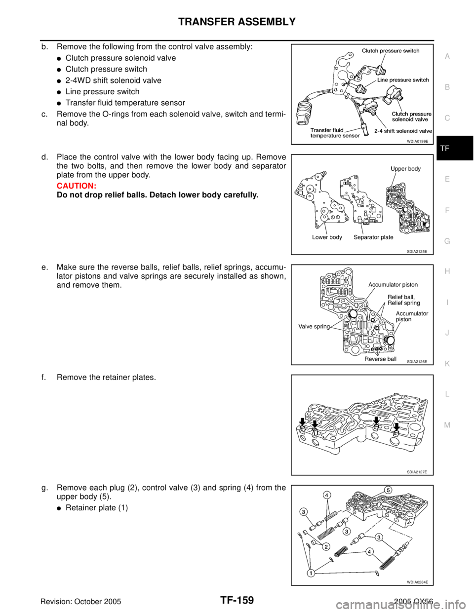
b. Remove the following from the control valve assembly:
�Clutch pressure solenoid valve
�Clutch pressure switch
�2-4WD shift solenoid valve
�Line pressure switch
�Transfer fluid temperature sensor
c. Remove the O-rings from each solenoid valve, switch and termi-
nal body.
d. Place the control valve with the lower body facing up. Remove
the two bolts, and then remove the lower body and separator
plate from the upper body.
CAUTION:
Do not drop relief balls. Detach lower body carefully.
e. Make sure the reverse balls, relief balls, relief springs, accumu-
lator pistons and valve springs are securely installed as shown,
and remove them.
f. Remove the retainer plates.
g. Remove each plug (2), control valve (3) and spring (4) from the
upper body (5).
�Retainer plate (1)
WDIA0199E
SDIA2125E
SDIA2126E
SDIA2127E
WDIA0284E
Page 3305 of 3419

TF-162
TRANSFER ASSEMBLY
Revision: October 20052005 QX56
Planetary Carrier
�Measure the end play of each pinion gear. If it is out of specifica-
tion, replace the planetary carrier assembly with a new one.
�Check the working face of each gear and bearing for damage,
burrs, partial wear, dents and other abnormality. If any is found,
replace the planetary carrier assembly with a new one.
Sun Gear
�Check if the oil passage of the sun gear assembly is clogged.
For this, try to pass a 3.6 mm (0.142 in) dia. pin through the oil
passage as shown.
�Check the sliding and contact surface of each gear and bearing
for damage, burrs, partial wear, dents, and other abnormality. If
any is found, replace the sun gear assembly with a new one.
Internal Gear
�Check the internal gear teeth for damage, partial wear, dents
and other abnormality. If any is found, replace the internal gear
with a new one.
Gears and Drive Chain
�Check the gear faces and shaft for wear, cracks, damage, and
seizure.
�Check the surfaces which contact the sun gear, clutch drum,
clutch hub, press flange, clutch piston and each bearing for
damage, peel, partial wear, dents, bending, or other abnormal
damage. If any is found, replace with a new one.Pinion gear end play : 0.1 - 0.7 mm (0.004 - 0.028 in)
PDIA0185E
PDIA0186E
SMT008D
SMT944C
Page 3306 of 3419

TRANSFER ASSEMBLY
TF-163
C
E
F
G
H
I
J
K
L
MA
B
TF
Revision: October 20052005 QX56
Bearing
�Make sure the bearings roll freely and are free from noise, pit-
ting and cracks.
Main Oil Pump
1. Check the inner and outer circumference, tooth face, and side-
face of the inner and outer gears for damage or abnormal wear.
2. Measure the side clearance between the main oil pump housing
edge and the inner and outer gears.
3. Make sure the side clearance is within specification. If the mea-
surement is out of specification, replace the inner and outer
gears with new ones as a set. Refer to TF-163, "
Main Oil Pump"
.
Sub-oil Pump
1. Check the inner and outer circumference, tooth face, and side-
face of the inner and outer gears for damage or abnormal wear.
2. Measure the side clearance between the sub oil pump housing
edge and the inner and outer gears.
3. Make sure the side clearance is within specification. If the mea-
surement is out of specification, replace the inner and outer
gears with new ones as a set. Refer to TF-163, "
Sub-oil Pump" .
Control Valve
�Check resistance between the terminals of the clutch pressure
solenoid valve, 2-4WD shift solenoid valve, clutch pressure
switch and the transfer fluid temperature sensor. Refer to TF-90,
"COMPONENT INSPECTION" (clutch pressure solenoid
valve), TF-94, "
COMPONENT INSPECTION" (2-4WD solenoid
valve), TF-107, "
COMPONENT INSPECTION" (clutch pressure
switch) and TF-104, "
COMPONENT INSPECTION" (transfer
fluid temperature sensor).
SDIA2175E
Specification : 0.015 - 0.035 mm (0.0006 - 0.0014 in)
SDIA2174E
Specification : 0.015 - 0.035 mm (0.0006 - 0.0014 in)
SDIA2173E
WDIA0199E
Page 3307 of 3419

TF-164
TRANSFER ASSEMBLY
Revision: October 20052005 QX56
�Check the sliding faces of the control valves and plugs for
abnormality. If any is found, replace the control valve assembly
with a new one. Refer to TF-182, "
Control Valve" .
CAUTION:
Replace control valve body together with clutch return
spring as a set.
�Check each control valve spring for damage or distortion. Also
check its free length, outer diameter and wire diameter. If any
damage or fatigue is found, replace the control valve body with a
new one. Refer to TF-182, "
Control Valve Spring" .
CAUTION:
Replace control valve body together with clutch return
spring as a set.
Clutch
�Check the drive plate facings and driven plate for damage,
cracks or other abnormality. If any abnormalities are found,
replace with a new one.
�Check the thickness of the drive plate facings and driven plate.
Refer to TF-164, "
Clutch" .
CAUTION:
�Measure facing thickness at 3 points to take an average.
�Check all drive and driven plates.
�Check return spring for damage or deformation.
�Do not remove spring from plate.
Return Spring
�Check the stamped mark shown. Then, check that the free
lengths, (include thickness of plate) are within specifications. If
any abnormality is found, replace with a new return spring
assembly of the same stamped number. Refer to TF-164,
"Return Spring" .
SMT947C
SMT948C
SMT949C
SDIA2176E
Page 3310 of 3419

TRANSFER ASSEMBLY
TF-167
C
E
F
G
H
I
J
K
L
MA
B
TF
Revision: October 20052005 QX56
d. Install the reverse balls, relief balls and relief springs, accumula-
tor pistons and valve springs to the upper body.
e. Install the lower body and separator plate to the upper body.
CAUTION:
Do not reuse separator plates.
f. With the lower body down, tighten the two bolts shown.
g. Apply ATF to the O-rings, and install them to each solenoid
valve, switch and terminal body.
CAUTION:
Do not reuse O-rings.
h. Install the following to the control valve assembly:
�Clutch pressure solenoid valve
�Clutch pressure switch
�2-4WD shift solenoid valve
�Line pressure switch
�Transfer fluid temperature sensor
10. Apply ATF to lip seals, and install them to the center case.
CAUTION:
�Do not reuse lip seals.
�There are 2 kinds of lip seals (lip seal of large inner diam-
eter: 5 pieces, lip seal of small inner diameter: 2 pieces).
Confirm their position for installation.
SDIA2126E
WDIA0200E
WDIA0198E
SDIA2123E
Page 3311 of 3419
TF-168
TRANSFER ASSEMBLY
Revision: October 20052005 QX56
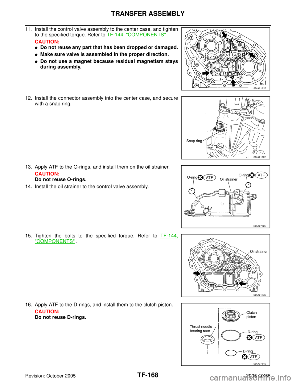
11. Install the control valve assembly to the center case, and tighten
to the specified torque. Refer to TF-144, "
COMPONENTS" .
CAUTION:
�Do not reuse any part that has been dropped or damaged.
�Make sure valve is assembled in the proper direction.
�Do not use a magnet because residual magnetism stays
during assembly.
12. Install the connector assembly into the center case, and secure
with a snap ring.
13. Apply ATF to the O-rings, and install them on the oil strainer.
CAUTION:
Do not reuse O-rings.
14. Install the oil strainer to the control valve assembly.
15. Tighten the bolts to the specified torque. Refer to TF-144,
"COMPONENTS" .
16. Apply ATF to the D-rings, and install them to the clutch piston.
CAUTION:
Do not reuse D-rings.
SDIA2121E
SDIA2122E
SDIA2782E
SDIA2 119 E
SDIA2781E