Page 2714 of 3419

HARNESS
PG-39
C
D
E
F
G
H
I
J
L
MA
B
PG
Revision: October 20052005 QX56
HARNESSPFP:24010
Harness LayoutEKS00BND
HOW TO READ HARNESS LAYOUT
The following Harness Layouts use a map style grid to help locate
connectors on the drawings:
�Main Harness, Console Sub-harness, Console Switch Sub-har-
ness and Optical Sensor Sub-harness
�Engine Room Harness LH View (Engine Compartment)
�Engine Room Harness RH View (Engine Compartment) and
Generator Sub-harness
�Engine Control Harness and Engine Control Sub-harness
�Chassis Harness and Rear Sonar Sensor Sub-harness
�Body Harness
�Body No. 2 Harness
To use the grid reference
1. Find the desired connector number on the connector list.
2. Find the grid reference.
3. On the drawing, find the crossing of the grid reference letter column and number row.
4. Find the connector number in the crossing zone.
5. Follow the line (if used) to the connector.
CONNECTOR SYMBOL
Main symbols of connector (in Harness Layout) are indicated below.
SEL252V
Connector typeWater proof type Standard type
Male Female Male Female
�Cavity: 4 or Less
�Relay connector
�Cavity: From 5 to 8
�Cavity: 9 or More
�Ground terminal etc.
—
Page 2735 of 3419
EKS00BNE
Use the chart below to find out what each wiring diagram code stands for.
Refer to the wiring diagram code in th")
PG-60
HARNESS
Revision: October 20052005 QX56
Wiring Diagram Codes (Cell Codes)EKS00BNE
Use the chart below to find out what each wiring diagram code stands for.
Refer to the wiring diagram code in the alphabetical index to find the location (page number) of each wiring
diagram.
Code Section Wiring Diagram Name
A/C,A ATC Auto Air Conditioner
A/SUSP RSU Rear Air Suspension
AF1B1 EC Air Fuel Ratio Sensor 1 (Bank 1)
AF1B2 EC Air Fuel Ratio Sensor 1 (Bank 2)
AF1HB1 EC Air Fuel Ratio Sensor 1 (Bank 1)
AF1HB2 EC Air Fuel Ratio Sensor 1 (Bank 2)
APPS1 EC Accelerator Pedal Position Sensor
APPS2 EC Accelerator Pedal Position Sensor
APPS3 EC Accelerator Pedal Position Sensor
ASC/BS EC ASCD Brake Switch
ASC/SW EC ASCD Steering Switch
ASCBOF EC ASCD Brake Switch
ASCIND EC ASCD Indicator
A/T AT A/T Assembly
AT/IND DI A/T Indicator Lamp
AUDIO AV Audio
AUTO/DP SE Automatic Drive Positioner
AUTO/L LT Auto Light Control
B/CLOS BL Back Door Auto Closure System
BACK/L LT Back-up Lamp
BRK/SW EC Brake Switch
CAN EC CAN Communication Line
CAN LAN CAN System
CHARGE SC Charging System
CHIME DI Warning Chime
CLOCK DI Clock
COOL/F EC Cooling Fan Control
COMBSW LT Combination Switch
COMM AV Audio Visual Communication System
COMPAS DI Compass and Thermometer
D/LOCK BL Power Door Lock
DEF GW Rear Window Defogger
DTRL LT Headlamp - With Daytime Light System
DVD AV DVD Entertainment System
ECM/PW EC ECM Power Supply for Back-Up
ECTS EC Engine Coolant Temperature Sensor
ETC1 EC Electric Throttle Control Function
ETC2 EC Throttle Control Motor Relay
ETC3 EC Throttle Control Motor
F/FOG LT Front Fog Lamp
F/PUMP EC Fuel Pump
FTTS EC Fuel Tank Temperature Sensor
FUELB1 EC Fuel Injection System Bank 1
FUELB2 EC Fuel Injection System Bank 2
H/AIM LT Headlamp Aiming Control
H/LAMP LT Headlamp
HORN WW Horn
Page 2747 of 3419
PG-72
STANDARDIZED RELAY
Revision: October 20052005 QX56
STANDARDIZED RELAYPFP:25230
DescriptionEKS00BNL
NORMAL OPEN, NORMAL CLOSED AND MIXED TYPE RELAYS
Relays can mainly be divided into three types: normal open, normal closed and mixed type relays.
TYPE OF STANDARDIZED RELAYS
SEL881H
SEL882H
1M 1 Make 2M 2 Make
1T 1 Transfer 1M·1B 1 Make 1 Break
Page 2748 of 3419
STANDARDIZED RELAY
PG-73
C
D
E
F
G
H
I
J
L
MA
B
PG
Revision: October 20052005 QX56
WKIA0253E
Page 2753 of 3419
PG-78
FUSE AND RELAY BOX
Revision: October 20052005 QX56
FUSE AND RELAY BOXPFP:24012
Terminal ArrangementEKS00BNP
WKIA2017E
Page 2827 of 3419
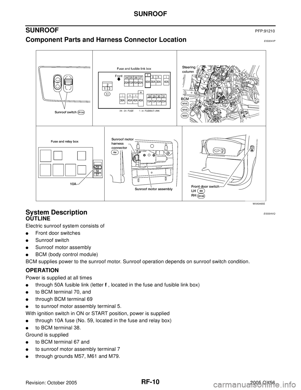
RF-10
SUNROOF
Revision: October 20052005 QX56
SUNROOFPFP:91210
Component Parts and Harness Connector LocationEIS004VP
System DescriptionEIS004VQ
OUTLINE
Electric sunroof system consists of
�Front door switches
�Sunroof switch
�Sunroof motor assembly
�BCM (body control module)
BCM supplies power to the sunroof motor. Sunroof operation depends on sunroof switch condition.
OPERATION
Power is supplied at all times
�through 50A fusible link (letter f , located in the fuse and fusible link box)
�to BCM terminal 70, and
�through BCM terminal 69
�to sunroof motor assembly terminal 5.
With ignition switch in ON or START position, power is supplied
�through 10A fuse (No. 59, located in the fuse and relay box)
�to BCM terminal 38.
Ground is supplied
�to BCM terminal 67 and
�to sunroof motor assembly terminal 7
�through grounds M57, M61 and M79.
WIIA0465E
Page 2835 of 3419

RF-18
SUNROOF
Revision: October 20052005 QX56
BCM Power Supply and Ground Circuit CheckEIS004W1
1. CHECK FUSE
Check the following BCM fuse and fusible link.
NOTE:
Refer to RF-10, "
Component Parts and Harness Connector Location" .
OK or NG
OK >> GO TO 2.
NG >> If fuse is blown, be sure to eliminate cause of blown fuse before installing new fuse. Refer to PG-
4, "POWER SUPPLY ROUTING CIRCUIT" .
2. CHECK POWER SUPPLY CIRCUIT
1. Turn ignition switch OFF.
2. Disconnect BCM connectors.
3. Check voltage between BCM connectors M18 and M20 termi-
nals 38, 70 and ground.
OK or NG
OK >> GO TO 3.
NG >> Repair or replace harness.
3. CHECK GROUND CIRCUIT
Check continuity between BCM connector M20 terminal 67 and
ground.
OK or NG
OK >> Power supply and ground circuit is OK.
NG >> Repair or replace harness.
Retained power operation does not operate properly.1. Check the retained power operation mode settingRF-112. BCM power supply and ground circuit checkRF-18
3. Door switch checkRF-21
4. Replace sunroof motor assemblyRF-27
Motor does not stop at the sunroof fully-open or fully-
closed position.1. Initialization procedure checkRF-11
2. Replace sunroof motor assemblyRF-27
Sunroof does not do the interruption detection. 1. Replace sunroof motor assemblyRF-27
Symptom Diagnostic procedure and repair order Refer to page
Component Parts Terminal No. (SIGNAL) Ampere No. Location
BCM38 (IGN power supply) 10A 59 Fuse and relay box
70 (BAT power supply) 50A f Fuse and fusible link box
ConnectorTerminals
(Wire color)
ConditionVo l ta g e
(Approx.)
(+) (–)
M18 38 (W/L)
GroundIgnition switch ON
Battery voltage
M20 70 (W/B) Igniting switch OFF
WIIA0229E
Connector Terminals (Wire color) Continuity
M20 67 (B) Ground YES
LIIA0915E
Page 2876 of 3419

RSU-1
REAR SUSPENSION
E SUSPENSION
CONTENTS
C
D
F
G
H
I
J
K
L
M
SECTION RSU
A
B
RSU
Revision: October 20052005 QX56 PRECAUTIONS .......................................................... 3
Precautions for Supplemental Restraint System
(SRS) “AIR BAG” and “SEAT BELT PRE-TEN-
SIONER” .................................................................. 3
Precautions for Rear Suspension ............................ 3
PREPARATION ........................................................... 4
Commercial Service Tools ........................................ 4
NOISE, VIBRATION, AND HARSHNESS (NVH)
TROUBLESHOOTING ................................................ 5
NVH Troubleshooting Chart ..................................... 5
CAN COMMUNICATION ............................................ 6
System Description .................................................. 6
TROUBLE DIAGNOSIS .............................................. 7
How to Perform Trouble Diagnoses for Quick and
Accurate Repair ....................................................... 7
INTRODUCTION ................................................... 7
CLARIFY CONCERN ............................................ 7
WORK FLOW ........................................................ 8
Component Parts and Harness Connector Location ..... 9
Wiring Diagram — A/SUSP — ............................... 10
Basic Inspection ..................................................... 12
AIR HOSES ......................................................... 12
POWER SYSTEM TERMINAL LOOSENESS
AND BATTERY INSPECTION ............................ 12
CK SUSP INDICATOR LAMP INSPECTION ...... 12
CK SUSP Indicator Lamp Timing ........................... 12
Control Unit Input/Output Signal Standard ............. 12
CONSULT-II Function (AIR LEVELIZER) ............... 13
CONSULT-II BASIC OPERATION PROCEDURE
... 13
WORK SUPPORT ............................................... 14
SELF-DIAGNOSIS .............................................. 14
DATA MONITOR ................................................. 15
ACTIVE TEST ..................................................... 16
TROUBLE DIAGNOSIS FOR SELF-DIAGNOSTIC
ITEMS ....................................................................... 17
Height Sensor System Inspection .......................... 17
Exhaust Valve Solenoid System Inspection ........... 19
Compressor Motor, Compressor Motor Relay and Circuit Inspection .................................................... 20
TROUBLE DIAGNOSES FOR SYMPTOMS ............ 23
Load Leveling Rear Air Suspension System Does
Not Operate ............................................................ 23
CK SUSP Indicator Lamp Stays On When Ignition
Switch Is Turned On ............................................... 24
REAR SUSPENSION ASSEMBLY ........................... 25
Components ........................................................... 25
On-Vehicle Inspection and Service ......................... 26
SHOCK ABSORBER INSPECTION .................... 26
Wheel Alignment Inspection ................................... 27
PRELIMINARY INSPECTION ............................. 27
GENERAL INFORMATION AND RECOMMEN-
DATIONS ............................................................. 27
THE ALIGNMENT PROCESS ............................. 28
CAMBER ............................................................. 28
TOE-IN ................................................................ 28
REAR SUSPENSION MEMBER ............................... 30
Removal and Installation ........................................ 30
REMOVAL ........................................................... 31
INSPECTION AFTER REMOVAL ....................... 32
INSTALLATION ................................................... 33
SHOCK ABSORBER ................................................ 34
Removal and Installation ........................................ 34
REMOVAL ........................................................... 34
INSTALLATION ................................................... 34
INSPECTION AFTER INSTALLATION ................ 34
SUSPENSION ARM .................................................. 35
Removal and Installation ........................................ 35
REMOVAL ........................................................... 35
INSPECTION AFTER REMOVAL ....................... 35
INSTALLATION ................................................... 36
FRONT LOWER LINK .............................................. 37
Removal and Installation ........................................ 37
REMOVAL ........................................................... 37
INSPECTION AFTER REMOVAL ....................... 37
INSTALLATION ................................................... 38