Page 3180 of 3419
![INFINITI QX4 2005 Factory Service Manual TROUBLE DIAGNOSIS
TF-37
C
E
F
G
H
I
J
K
L
MA
B
TF
Revision: October 20052005 QX56
WAIT DETCT SW [ON/
OFF]Condition of wait detec-
tion switch
�Vehicle stopped
�Engine running
�A/T selector lever “N�](/manual-img/42/57035/w960_57035-3179.png "INFINITI QX4 2005 Factory Service Manual TROUBLE DIAGNOSIS
TF-37
C
E
F
G
H
I
J
K
L
MA
B
TF
Revision: October 20052005 QX56
WAIT DETCT SW [ON/
OFF]Condition of wait detec-
tion switch
�Vehicle stopped
�Engine running
�A/T selector lever “N�")
TROUBLE DIAGNOSIS
TF-37
C
E
F
G
H
I
J
K
L
MA
B
TF
Revision: October 20052005 QX56
WAIT DETCT SW [ON/
OFF]Condition of wait detec-
tion switch
�Vehicle stopped
�Engine running
�A/T selector lever “N” posi-
tion
�Brake pedal depressed4WD shift switch: 2WD,
AUTO or 4HOFF
4WD shift switch: 4H to
4LO (While actuator
motor is operating.)OFF → ON
4WD shift switch: 4LO to
4H (While actuator motor
is operating.)OFF → ON
4WD shift switch: 4LO ON
LINE PRES SW [ON/
OFF]Condition of line pres-
sure switch
�A/T selector lever “D” position
�4WD shift switch: 2WD, AUTO or 4HON
�Except the above
�The vehicle has been left
at room temperature for 5
minutes and more with
ignition switch in “OFF”
position.�Ignition switch: ON
�A/T selector lever: “P”
or "N" position
�4WD shift switch: other
than AUTOOFF
CL PRES SW [ON /
OFF]Condition of clutch pres-
sure switch
�Vehicle stopped
�Engine running
�A/T selector lever “D” position
�4WD shift switch: AUTO or 4H (“Wait” function is not
operating.)ON
�Vehicle stopped
�Engine running
�4WD shift switch: 2WD (“Wait” function is not operat-
ing.)OFF
N POSI SW AT [ON/
OFF]Input condition from A/T
PNP switch
�Vehicle stopped
�Engine running
�Brake pedal depressedA/T selector lever posi-
tion: NON
Except the above OFF
R POSI SW AT [ON/
OFF]Input condition from A/T
PNP switch
�Vehicle stopped
�Engine running
�Brake pedal depressedA/T selector lever posi-
tion: RON
Except the above OFF
P POSI SW AT [ON/
OFF]Input condition from A/T
PNP switch
�Vehicle stopped
�Engine running
�Brake pedal depressedA/T selector lever posi-
tion: PON
Except the above OFF
ABS OPER SW [ON/
OFF]Condition of ABS operat-
ingABS is operating. ON
ABS is not operating. OFF
VDC OPER SW [ON/
OFF]Condition of VDC operat-
ingVDC is operating. ON
VDC is not operating. OFF
TCS OPER SW [ON/
OFF]Condition of TCS operat-
ingTCS is operating. ON
TCS is not operating. OFF
THROTTLE POSI [0.0/8]Condition of throttle
openingWhen depressing accelerator pedal
(Value rises gradually in response to throttle position.)0.0/8 - 8.0/8
4WD MODE [AUTO/
LOCK/2WD/4L]Control status of 4WD
(Output condition of
4WD shift indicator lamp
and 4LO indicator lamp)
�Vehicle stopped
�Engine running
�A/T selector lever “N” posi-
tion
�Brake pedal depressed4WD shift switch: 2WD 2WD
4WD shift switch: AUTO AUTO
4WD shift switch: 4H LOCK
4WD shift switch: 4LO 4L Monitored item [Unit] Content Condition Display value
Page 3292 of 3419
TRANSFER ASSEMBLY
TF-149
C
E
F
G
H
I
J
K
L
MA
B
TF
Revision: October 20052005 QX56
17. Remove the 2-4 sleeve and L-H sleeve from the 2-4 fork and L-
H fork respectively.
18. Drive out the retaining pin from the shift rod, using suitable tool.
19. Remove the L-H fork, 2-4 fork, shift fork spring and fork guide
from the shift rod.
20. Remove the oil seal from the front case, using suitable tool.
CAUTION:
Do not damage front case or sun gear.
21. Remove the snap ring from the sun gear.
CAUTION:
Do not damage front case or sun gear.
SMT992C
WDIA0134E
SDIA2142E
SDIA2143E
SDIA2144E
Page 3336 of 3419
TROUBLE DIAGNOSES
WT-11
C
D
F
G
H
I
J
K
L
MA
B
WT
Revision: October 20052005 QX56
TROUBLE DIAGNOSESPFP:00004
Wiring DiagramEES001I5
WEWA0032E
Page 3341 of 3419

WT-16
TROUBLE DIAGNOSES
Revision: October 20052005 QX56
Transmitter Wake Up OperationEES001I8
NOTE:
This procedure must be done after replacement of a low tire pressure warning sensor or BCM. New
replacement transmitters are provided "asleep" and must first be "woken up" using Transmitter Acti-
vation Tool J-45295 before ID registration can be performed.
WITH TRANSMITTER ACTIVATION TOOL
1. With the transmitter activation tool (J-45295) pushed against the
front left transmitter, press the button for 5 seconds.
�With ignition switch ON, as the hazard warning lamp flashes
per the following diagram, the respective transmitter then
must be woken up.
2. When the BCM finishes assigning each tire ID, the BCM flashes the hazard warning lamps and trailer
flasher lamps (if equipped) and sends flashing indicator status by CAN according to the following time
chart. Please see trailer flasher specification details of trailer flashing lamps since the BCM controls trailer
flasher lamps as brake lamps. Refer to LT- 1 2 3 , "
TRAILER TOW"
3. After completing wake up of all transmitters, make sure low tire pressure warning lamp goes out.Tool number — (J-45295)
LEIA0036E
LEIA0059E
Page 3366 of 3419
FRONT WIPER AND WASHER SYSTEM
WW-7
C
D
E
F
G
H
I
J
L
MA
B
WW
Revision: October 20052005 QX56
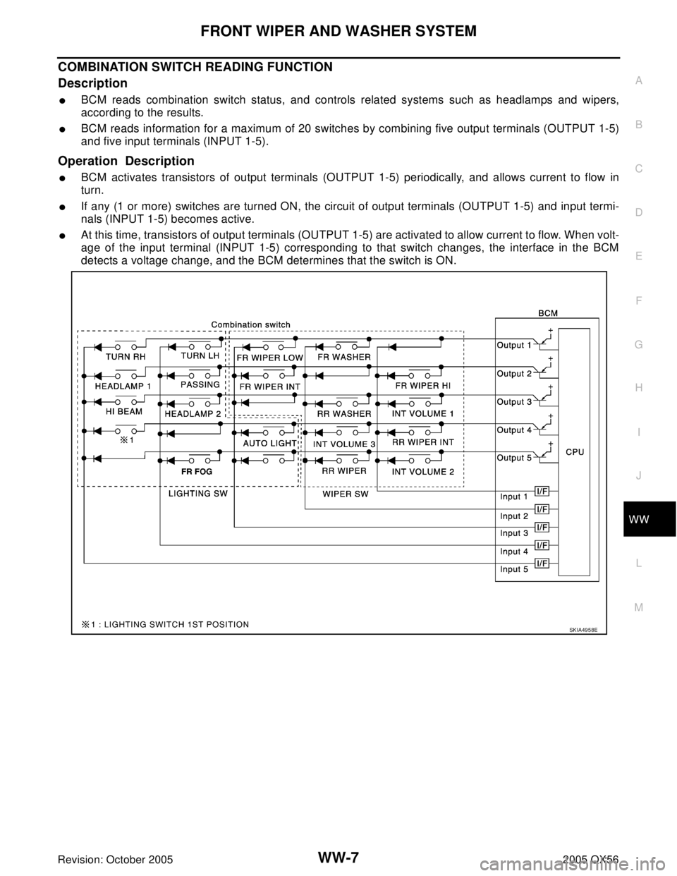
COMBINATION SWITCH READING FUNCTION
Description
�BCM reads combination switch status, and controls related systems such as headlamps and wipers,
according to the results.
�BCM reads information for a maximum of 20 switches by combining five output terminals (OUTPUT 1-5)
and five input terminals (INPUT 1-5).
Operation Description
�BCM activates transistors of output terminals (OUTPUT 1-5) periodically, and allows current to flow in
turn.
�If any (1 or more) switches are turned ON, the circuit of output terminals (OUTPUT 1-5) and input termi-
nals (INPUT 1-5) becomes active.
�At this time, transistors of output terminals (OUTPUT 1-5) are activated to allow current to flow. When volt-
age of the input terminal (INPUT 1-5) corresponding to that switch changes, the interface in the BCM
detects a voltage change, and the BCM determines that the switch is ON.
SKIA4958E