Page 2059 of 4731
![INFINITI FX35 2005 Service Manual EC-666
[VQ35DE]
INJECTOR CIRCUIT
Revision: 2005 July 2005 FX
7. DETECT MALFUNCTIONING PART
Check the following.
�Harness connectors M82, F102
�Harness connectors F50, F251
�Fuse block (J/B) connector](/manual-img/42/57020/w960_57020-2058.png "INFINITI FX35 2005 Service Manual EC-666
[VQ35DE]
INJECTOR CIRCUIT
Revision: 2005 July 2005 FX
7. DETECT MALFUNCTIONING PART
Check the following.
�Harness connectors M82, F102
�Harness connectors F50, F251
�Fuse block (J/B) connector")
EC-666
[VQ35DE]
INJECTOR CIRCUIT
Revision: 2005 July 2005 FX
7. DETECT MALFUNCTIONING PART
Check the following.
�Harness connectors M82, F102
�Harness connectors F50, F251
�Fuse block (J/B) connector M4
�10A fuse
�Harness for open or short between injector and fuse
>> Repair open circuit or short to ground or short to power in harness or connectors.
8. CHECK INJECTOR OUTPUT SIGNAL CIRCUIT FOR OPEN AND SHORT
1. Turn ignition switch OFF.
2. Disconnect ECM harness connector.
3. Check harness continuity between injector terminal 2 and ECM terminals 21, 22, 23, 40, 41, 42. Refer to Wiring Diagram.
4. Also check harness for short to ground and short to power.
OK or NG
OK >> GO TO 10.
NG >> GO TO 9.
9. DETECT MALFUNCTIONING PART
Check the following.
�Harness connectors F251, F50
�Harness for open or short between injector and ECM
>> Repair open circuit or short to ground or short to power in harness or connectors.
10. CHECK INJECTOR
Refer to EC-667, "
Component Inspection" .
OK or NG
OK >> GO TO 11.
NG >> Replace injector.
11 . CHECK INTERMITTENT INCIDENT
Refer to EC-163, "
TROUBLE DIAGNOSIS FOR INTERMITTENT INCIDENT" .
>> INSPECTION END
Continuity should exist.
Page 2061 of 4731
![INFINITI FX35 2005 Service Manual EC-668
[VQ35DE]
FUEL PUMP CIRCUIT
Revision: 2005 July 2005 FX
FUEL PUMP CIRCUITPFP:17042
DescriptionABS006YF
SYSTEM DESCRIPTION
*: ECM determines the start signal status by the signals of engine speed](/manual-img/42/57020/w960_57020-2060.png "INFINITI FX35 2005 Service Manual EC-668
[VQ35DE]
FUEL PUMP CIRCUIT
Revision: 2005 July 2005 FX
FUEL PUMP CIRCUITPFP:17042
DescriptionABS006YF
SYSTEM DESCRIPTION
*: ECM determines the start signal status by the signals of engine speed")
EC-668
[VQ35DE]
FUEL PUMP CIRCUIT
Revision: 2005 July 2005 FX
FUEL PUMP CIRCUITPFP:17042
DescriptionABS006YF
SYSTEM DESCRIPTION
*: ECM determines the start signal status by the signals of engine speed and battery voltage.
The ECM activates the fuel pump for several seconds after the ignition switch is turned ON to improve engine
start ability. If the ECM receives a engine speed signal from the camshaft position sensor (PHASE), it knows
that the engine is rotating, and causes the pump to operate. If the engine speed signal is not received when
the ignition switch is ON, the engine stalls. The ECM stops pump operation and prevents battery discharging,
thereby improving safety. The ECM does not directly drive the fuel pump. It controls the ON/OFF fuel pump
relay, which in turn controls the fuel pump.
COMPONENT DESCRIPTION
A turbine type design fuel pump is used in the furl tank.
CONSULT-II Reference Value in Data Monitor ModeABS006YG
Specification data are reference values.
Sensor Input Signal to ECM ECM Function Actuator
Crankshaft position sensor (POS)
Camshaft position sensor (PHASE) Engine speed*
Fuel pump control Fuel pump relay
Battery Battery voltage*
Condition Fuel pump operation
Ignition switch is turned to ON. Operates for 1 second.
Engine running and cranking Operates.
When engine is stopped Stops in 1.5 seconds.
Except as shown above Sto ps.
PBIB1569E
MONITOR ITEM CONDITION SPECIFICATION
FUEL PUMP RLY
�For 1 second after turning ignition switch ON
�Engine running or cranking ON
�Except above conditions OFF
Page 2063 of 4731
![INFINITI FX35 2005 Service Manual EC-670
[VQ35DE]
FUEL PUMP CIRCUIT
Revision: 2005 July 2005 FX
Specification data are reference values and are measured between each terminal and ground.
CAUTION:
Do not use ECM ground terminals when](/manual-img/42/57020/w960_57020-2062.png "INFINITI FX35 2005 Service Manual EC-670
[VQ35DE]
FUEL PUMP CIRCUIT
Revision: 2005 July 2005 FX
Specification data are reference values and are measured between each terminal and ground.
CAUTION:
Do not use ECM ground terminals when")
EC-670
[VQ35DE]
FUEL PUMP CIRCUIT
Revision: 2005 July 2005 FX
Specification data are reference values and are measured between each terminal and ground.
CAUTION:
Do not use ECM ground terminals when measuring input/output voltage. Doing so may result in dam-
age to the ECM's transistor. Use a ground other than ECM terminals, such as the ground.
Diagnostic ProcedureABS006YI
1. CHECK OVERALL FUNCTION
1. Turn ignition switch ON.
2. Pinch fuel feed hose with two fingers. Fuel pressure pulsation should be felt on the fuel feed hose
for 1 second after ignition switch is turned ON.
OK or NG
OK >> INSPECTION END
NG >> GO TO 2.
2. CHECK FUEL PUMP POWER SUPPLY CIRCUIT-I
1. Turn ignition switch OFF.
2. Disconnect ECM harness connector.
3. Turn ignition switch ON.
4. Check voltage between ECM terminal 113 and ground with CONSULT-II or tester.
OK or NG
OK >> GO TO 5.
NG >> GO TO 3.
3. CHECK FUEL PUMP POWER SUPPLY CIRCUIT-II
Check voltage between IPDM E/R terminal 40 and ground with CONSULT-II or tester.
OK or NG
OK >> GO TO 4.
NG >> GO TO 11.
TER-
MINAL NO. WIRE
COLOR ITEM CONDITION DATA (DC Voltage)
11 3 G Y / R F u e l p u m p r e l a y [Ignition switch: ON]
�For 1 second after turning ignition switch ON
[Engine is running] 0 - 1.5V
[Ignition switch: ON]
�More than 1 second after turning ignition
switch ON BATTERY VOLTAGE
(11 - 14V)
PBIB1612E
Voltage: Battery voltage
PBIB1187E
Voltage: Battery voltage
Page 2064 of 4731
FUEL PUMP CIRCUIT EC-671
[VQ35DE]
C
D E
F
G H
I
J
K L
M A
EC
Revision: 2005 July 2005 FX
4. DETECT MALFUNCTIONING PART
Check the following.
�Harness connectors E211, M41
�Harness for open or short between IPDM E/R and ECM
>> Repair open circuit or short to ground or short to power in harness or connectors.
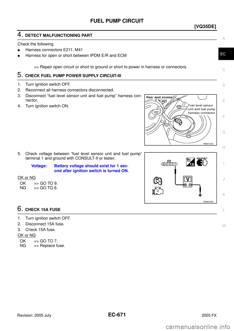
5. CHECK FUEL PUMP POWER SUPPLY CIRCUIT-III
1. Turn ignition switch OFF.
2. Reconnect all harness connectors disconnected.
3. Disconnect “fuel level sensor unit and fuel pump” harness con- nector.
4. Turn ignition switch ON.
5. Check voltage between “fuel level sensor unit and fuel pump” terminal 1 and ground with CONSULT-II or tester.
OK or NG
OK >> GO TO 9.
NG >> GO TO 6.
6. CHECK 15A FUSE
1. Turn ignition switch OFF.
2. Disconnect 15A fuse.
3. Check 15A fuse.
OK or NG
OK >> GO TO 7.
NG >> Replace fuse.
PBIB1572E
Voltage: Battery voltage should exist for 1 sec-
ond after ignition switch is turned ON.
PBIB0795E
Page 2069 of 4731
![INFINITI FX35 2005 Service Manual EC-676
[VQ35DE]
REFRIGERANT PRESSURE SENSOR
Revision: 2005 July 2005 FX
Specification data are reference values and are measured between each terminal and ground.
CAUTION:
Do not use ECM ground term](/manual-img/42/57020/w960_57020-2068.png "INFINITI FX35 2005 Service Manual EC-676
[VQ35DE]
REFRIGERANT PRESSURE SENSOR
Revision: 2005 July 2005 FX
Specification data are reference values and are measured between each terminal and ground.
CAUTION:
Do not use ECM ground term")
EC-676
[VQ35DE]
REFRIGERANT PRESSURE SENSOR
Revision: 2005 July 2005 FX
Specification data are reference values and are measured between each terminal and ground.
CAUTION:
Do not use ECM ground terminals when measuring input/output voltage. Doing so may result in dam-
age to the ECM's transistor. Use a ground other than ECM terminals, such as the ground.
Diagnostic ProcedureABS006YN
1. CHECK REFRIGERANT PRESSURE SENSOR OVERALL FUNCTION
1. Start engine and warm it up to normal operating temperature.
2. Turn A/C switch and blower switch ON.
3. Check voltage between ECM terminal 70 and ground with CON- SULT-II or tester.
OK or NG
OK >> INSPECTION END
NG >> GO TO 2.
2. CHECK GROUND CONNECTIONS
1. Turn A/C switch and blower switch OFF.
2. Stop engine.
3. Turn ignition switch OFF.
4. Loosen and retighten ground three screws on the body. Refer to EC-170, "
Ground Inspection" .
OK or NG
OK >> GO TO 3.
NG >> Repair or replace ground connections.
TER-
MINAL NO. WIRE
COLOR ITEM CONDITION DATA (DC Voltage)
49 PU Sensor power supply
(Refrigerant pressure sen-
sor) [Ignition switch: ON]
Approximately 5V
67 B/W Sensor ground [Engine is running]
�Warm-up condition
�Idle speed Approximately 0V
70 L/R Refrigerant pressure sensor [Engine is running]
�Warm-up condition
�Both A/C switch and blower switch are ON
(Compressor operates) 1.0 - 4.0V
Voltage: 1.0 - 4.0V
PBIB1188E
PBIB2625E
Page 2070 of 4731
![INFINITI FX35 2005 Service Manual REFRIGERANT PRESSURE SENSOR EC-677
[VQ35DE]
C
D E
F
G H
I
J
K L
M A
EC
Revision: 2005 July 2005 FX
3. CHECK REFRIGERANT PRESSURE SENSOR POWER SUPPLY CIRCUIT
1. Disconnect refrigerant pre](/manual-img/42/57020/w960_57020-2069.png "INFINITI FX35 2005 Service Manual REFRIGERANT PRESSURE SENSOR EC-677
[VQ35DE]
C
D E
F
G H
I
J
K L
M A
EC
Revision: 2005 July 2005 FX
3. CHECK REFRIGERANT PRESSURE SENSOR POWER SUPPLY CIRCUIT
1. Disconnect refrigerant pre")
REFRIGERANT PRESSURE SENSOR EC-677
[VQ35DE]
C
D E
F
G H
I
J
K L
M A
EC
Revision: 2005 July 2005 FX
3. CHECK REFRIGERANT PRESSURE SENSOR POWER SUPPLY CIRCUIT
1. Disconnect refrigerant pressure sensor harness connector.
2. Turn ignition switch ON.
3. Check voltage between refrigerant pressure sensor terminal 1 and ground with CONSULT-II or tester.
OK or NG
OK >> GO TO 5.
NG >> GO TO 4.
4. DETECT MALFUNCTIONING PART
Check the following.
�Harness connectors E18, F48
�Harness for open or short between ECM and refrigerant pressure sensor
>> Repair open circuit or short to ground or short to power in harness or connectors.
5. CHECK REFRIGERANT PRESSURE SENSOR GROUND CIRCUIT FOR OPEN AND SHORT
1. Turn ignition switch OFF.
2. Disconnect ECM harness connector.
3. Check harness continuity between refrigerant pressure sensor terminal 3 and ECM terminal 67. Refer to Wiring Diagram.
4. Also check harness for short to ground and short to power.
OK or NG
OK >> GO TO 7.
NG >> GO TO 6.
6. DETECT MALFUNCTIONING PART
Check the following.
�Harness connectors E18, F48
�Harness for open or short between ECM and refrigerant pressure sensor
>> Repair open circuit or short to ground or short to power in harness or connectors.
PBIB2007E
Voltage: Approximately 5V
PBIB0188E
Continuity should exist.
Page 2072 of 4731
![INFINITI FX35 2005 Service Manual ELECTRICAL LOAD SIGNAL EC-679
[VQ35DE]
C
D E
F
G H
I
J
K L
M A
EC
Revision: 2005 July 2005 FX
ELECTRICAL LOAD SIGNALPFP:25350
DescriptionABS006YP
The electrical load signal (Headlamp swit](/manual-img/42/57020/w960_57020-2071.png "INFINITI FX35 2005 Service Manual ELECTRICAL LOAD SIGNAL EC-679
[VQ35DE]
C
D E
F
G H
I
J
K L
M A
EC
Revision: 2005 July 2005 FX
ELECTRICAL LOAD SIGNALPFP:25350
DescriptionABS006YP
The electrical load signal (Headlamp swit")
ELECTRICAL LOAD SIGNAL EC-679
[VQ35DE]
C
D E
F
G H
I
J
K L
M A
EC
Revision: 2005 July 2005 FX
ELECTRICAL LOAD SIGNALPFP:25350
DescriptionABS006YP
The electrical load signal (Headlamp switch signal, etc.) is transferred through the CAN communication line
from BCM to ECM via IPDM E/R.
CONSULT-II Reference Value in Data Monitor ModeABS006YQ
Specification data are reference values.
Diagnostic ProcedureABS006YR
1. CHECK LOAD SIGNAL CIRCUIT OVERALL FUNCTION-I
1. Turn ignition switch ON.
2. Connect CONSULT-II and select “DATA MONITOR” mode.
3. Select “LOAD SIGNAL” and check indication under the following conditions.
OK or NG
OK >> GO TO 2.
NG >> GO TO 3.
2. CHECK LOAD SIGNAL CIRCUIT OVERALL FUNCTION-II
Check “LOAD SIGNAL” indication under the following conditions.
OK or NG
OK >> INSPECTION END
NG >> GO TO 4.
3. CHECK REAR WINDOW DEFOGGER SYSTEM
Refer to GW-86, "
REAR WINDOW DEFOGGER" .
>> INSPECTION END
4. CHECK HEADLAMP SYSTEM
Refer to LT- 7 , "
HEADLAMP - XENON TYPE -" .
>> INSPECTION END
MONITOR ITEM CONDITION SPECIFICATION
LOAD SIGNAL
�Ignition switch: ON Rear window defogger switch is ON
and/or lighting switch is in 2nd. ON
Rear window defogger switch is OFF
and lighting switch is OFF. OFF
Condition Indication
Rear window defogger switch: ON ON
Rear window defogger switch: OFF OFF
PBIB0103E
Condition Indication
Lighting switch: ON at 2nd position ON Lighting switch: OFF OFF
PBIB0103E
Page 2073 of 4731
EC-680
[VQ35DE]
ICC BRAKE SWITCH
Revision: 2005 July 2005 FX
ICC BRAKE SWITCHPFP:25320
Component DescriptionABS006YS
When the brake pedal is depressed, ICC brake switch is turned OFF
and stop lamp switch is turned ON. ECM detects the state of the
brake pedal by this input of two kinds (ON/OFF signal)
Refer to ACS-6, "
DESCRIPTION" for the ICC function.
CONSULT-II Reference Value in Data Monitor ModeABS006YT
Specification data are reference values.
PBIB1539E
MONITOR ITEM CONDITION SPECIFICATION
BRAKE SW1
(ICC brake switch)
�Ignition switch: ON�Brake pedal: Fully released ON
�Brake pedal: Slightly depressed OFF
BRAKE SW2
(stop lamp switch)
�Ignition switch: ON�Brake pedal: Fully released OFF
�Brake pedal: Slightly depressed ON
![INFINITI FX35 2005 Service Manual EC-680
[VQ35DE]
ICC BRAKE SWITCH
Revision: 2005 July 2005 FX
ICC BRAKE SWITCHPFP:25320
Component DescriptionABS006YS
When the brake pedal is depressed, ICC brake switch is turned OFF
and stop lamp sw](/manual-img/42/57020/w960_57020-2072.png "INFINITI FX35 2005 Service Manual EC-680
[VQ35DE]
ICC BRAKE SWITCH
Revision: 2005 July 2005 FX
ICC BRAKE SWITCHPFP:25320
Component DescriptionABS006YS
When the brake pedal is depressed, ICC brake switch is turned OFF
and stop lamp sw")