Page 2152 of 4731
![INFINITI FX35 2005 Service Manual ON BOARD DIAGNOSTIC (OBD) SYSTEM EC-759
[VK45DE]
C
D E
F
G H
I
J
K L
M A
EC
Revision: 2005 July 2005 FX
3. Touch “SELF-DIAG RESULTS”.
4. Touch “ERASE”. [The DTC in the TCM (Trans](/manual-img/42/57020/w960_57020-2151.png "INFINITI FX35 2005 Service Manual ON BOARD DIAGNOSTIC (OBD) SYSTEM EC-759
[VK45DE]
C
D E
F
G H
I
J
K L
M A
EC
Revision: 2005 July 2005 FX
3. Touch “SELF-DIAG RESULTS”.
4. Touch “ERASE”. [The DTC in the TCM (Trans")
ON BOARD DIAGNOSTIC (OBD) SYSTEM EC-759
[VK45DE]
C
D E
F
G H
I
J
K L
M A
EC
Revision: 2005 July 2005 FX
3. Touch “SELF-DIAG RESULTS”.
4. Touch “ERASE”. [The DTC in the TCM (Transmission control module) will be erased.] Then touch “BACK” twice.
5. Touch “ENGINE”.
6. Touch “SELF-DIAG RESULTS”.
7. Touch “ERASE”. (The DTC in the ECM will be erased.)
With GST
The emission related diagnostic information in the ECM can be erased by selecting Service $04 with GST.
NOTE:
If the DTC is not for A/T related items (see EC-707
), skip step 2.
1. If the ignition switch stays ON after repair work, be sure to turn ignition switch OFF once. Wait at least 10 seconds and then turn it ON (engine stopped) again.
2. Perform AT- 4 2 , "
HOW TO ERASE DTC (WITH GST)" . (The DTC in TCM will be erased.)
3. Select Service $04 with GST (Generic Scan Tool).
No Tools
NOTE:
If the DTC is not for A/T related items (see EC-707
), skip step 2.
1. If the ignition switch stays ON after repair work, be sure to turn ignition switch OFF once. Wait at least 10 seconds and then turn it ON (engine stopped) again.
2. Perform AT- 4 2 , "
HOW TO ERASE DTC (NO TOOLS)" . (The DTC in TCM will be erased.)
3. Change the diagnostic test mode from Mode II to Mode I by depressing the accelerator pedal. Refer to EC-762, "
HOW TO SWITCH DIAGNOSTIC TEST MODE" .
�If the battery is disconnected, the emission-related diagnostic information will be lost within 24
hours.
SCIA5671E
Page 2153 of 4731
EC-760
[VK45DE]
ON BOARD DIAGNOSTIC (OBD) SYSTEM
Revision: 2005 July 2005 FX
�The following data are cleared when the ECM memory is erased.
–Diagnostic trouble codes
–1st trip diagnostic trouble codes
–Freeze frame data
–1st trip freeze frame data
–System readiness test (SRT) codes
–Test values
Actual work procedures are explained using a DTC as an example. Be careful so that not only the DTC, but all
of the data listed above, are cleared from the ECM memory during work procedures.
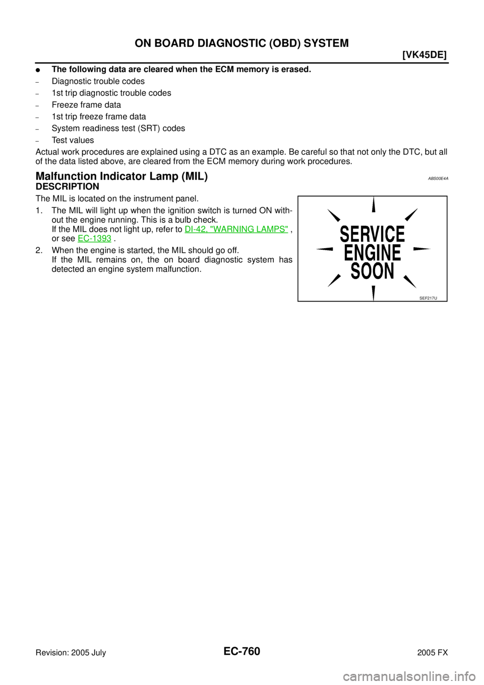
Malfunction Indicator Lamp (MIL)ABS00E4A
DESCRIPTION
The MIL is located on the instrument panel.
1. The MIL will light up when the ignition switch is turned ON with- out the engine running. This is a bulb check.
If the MIL does not light up, refer to DI-42, "
WARNING LAMPS" ,
or see EC-1393
.
2. When the engine is started, the MIL should go off. If the MIL remains on, the on board diagnostic system has
detected an engine system malfunction.
SEF217U
Page 2154 of 4731
![INFINITI FX35 2005 Service Manual ON BOARD DIAGNOSTIC (OBD) SYSTEM EC-761
[VK45DE]
C
D E
F
G H
I
J
K L
M A
EC
Revision: 2005 July 2005 FX
ON BOARD DIAGNOSTIC SYSTEM FUNCTION
The on board diagnostic system has the followin](/manual-img/42/57020/w960_57020-2153.png "INFINITI FX35 2005 Service Manual ON BOARD DIAGNOSTIC (OBD) SYSTEM EC-761
[VK45DE]
C
D E
F
G H
I
J
K L
M A
EC
Revision: 2005 July 2005 FX
ON BOARD DIAGNOSTIC SYSTEM FUNCTION
The on board diagnostic system has the followin")
ON BOARD DIAGNOSTIC (OBD) SYSTEM EC-761
[VK45DE]
C
D E
F
G H
I
J
K L
M A
EC
Revision: 2005 July 2005 FX
ON BOARD DIAGNOSTIC SYSTEM FUNCTION
The on board diagnostic system has the following four functions.
When there is an open circuit on MIL circuit, the ECM cannot warn the driver by lighting up MIL when there is
malfunction on engine control system.
Therefore, when electrical controlled throttle and part of ECM related diagnoses are continuously detected as
NG for 5 trips, ECM warns the driver that engine control system malfunctions and MIL circuit is open by means
of operating fail-safe function.
The fail-safe function also operates when above diagnoses except MIL circuit are detected and demands the
driver to repair the malfunction.
MIL Flashing Without DTC
�When any SRT codes are not set, MIL may flash without DTC. For the details, refer to EC-754, "How to
Display SRT Status" .
�If the ECM is in Diagnostic Test Mode II, MIL may flash when engine is running. In this case, check ECM
diagnostic test mode. EC-762, "
HOW TO SWITCH DIAGNOSTIC TEST MODE" .
How to switch the diagnostic test (function) modes, and details of the above functions are described later.
EC-762, "
HOW TO SWITCH DIAGNOSTIC TEST MODE" .
The following emission-related diagnostic information is cleared when the ECM memory is erased.
–Diagnostic trouble codes
–1st trip diagnostic trouble codes
–Freeze frame data
–1st trip freeze frame data
–System readiness test (SRT) codes
Diagnostic Test
Mode KEY and ENG.
Status Function Explanation of Function
Mode I Ignition switch in ON position
Engine stopped BULB CHECK This function checks the MIL bulb for damage (blown,
open circuit, etc.).
If the MIL does not come on, check MIL circuit.
Engine running MALFUNCTION WARNING This is a usual driving condition. When a malfunction is
detected twice in two consecutive driving cycles (two trip
detection logic), the MIL will light up to inform the driver
that a malfunction has been detected.
The following malfunctions will light up or blink the MIL in
the 1st trip.
�Misfire (Possible three way catalyst damage)
�One trip detection diagnoses
Mode II Ignition switch in ON position
Engine stopped SELF-DIAGNOSTIC
RESULTS This function allows DTCs and 1st trip DTCs to be read.
Engine running HEATED OXYGEN SENSOR 1 MONITOR This function allows the fuel mixture condition (lean or
rich), monitored by heated oxygen sensor 1, to be read.
Engine operating condition in fail-safe mode Engine speed will not rise more than 2,500 rpm due to the fuel cut
Page 2155 of 4731
![INFINITI FX35 2005 Service Manual EC-762
[VK45DE]
ON BOARD DIAGNOSTIC (OBD) SYSTEM
Revision: 2005 July 2005 FX
–Test values
HOW TO SWITCH DIAGNOSTIC TEST MODE
NOTE:
�It is better to count the time accurately with a clock.
�It is imp](/manual-img/42/57020/w960_57020-2154.png "INFINITI FX35 2005 Service Manual EC-762
[VK45DE]
ON BOARD DIAGNOSTIC (OBD) SYSTEM
Revision: 2005 July 2005 FX
–Test values
HOW TO SWITCH DIAGNOSTIC TEST MODE
NOTE:
�It is better to count the time accurately with a clock.
�It is imp")
EC-762
[VK45DE]
ON BOARD DIAGNOSTIC (OBD) SYSTEM
Revision: 2005 July 2005 FX
–Test values
HOW TO SWITCH DIAGNOSTIC TEST MODE
NOTE:
�It is better to count the time accurately with a clock.
�It is impossible to switch the diagnostic mode when an accelerator pedal position sensor circuit
has a malfunction.
�Always ECM returns to Diagnostic Test Mode I after ignition switch is turned OFF.
How to Set Diagnostic Test Mode II (Self-diagnostic Results)
1. Confirm that accelerator pedal is fully released, turn ignition switch ON and wait 3 seconds.
2. Repeat the following procedure quickly five times within 5 seconds.
a. Fully depress the accelerator pedal.
b. Fully release the accelerator pedal.
3. Wait 7 seconds, fully depress the accelerator pedal and keep it for approx. 10 seconds until the MIL starts blinking.
NOTE:
Do not release the accelerator pedal for 10 seconds if MIL may start blinking on the halfway of this
10 seconds. This blinking is displaying SRT status and is continued for another 10 seconds. For
the details, refer to EC-754, "
How to Display SRT Status" .
4. Fully release the accelerator pedal. ECM has entered to Diagnostic Test Mode II (Self-diagnostic results).
NOTE:
Wait until the same DTC (or 1st trip DTC) appears to confirm all DTCs certainly.
How to Set Diagnostic Test Mode II (Heated Oxygen Sensor 1 Monitor)
1. Set the ECM in Diagnostic Test Mode II (Self-diagnostic results). Refer to EC-762, "How to Set Diagnostic
Test Mode II (Self-diagnostic Results)" .
2. Start Engine. ECM has entered to Diagnostic Test Mode II (Heated oxygen sensor 1 monitor).
ECM will start heated oxygen sensor 1 monitoring from the bank 1 sensor.
How to Switch Monitored Sensor From Bank 1 to Bank 2 or Vice Versa
1. Fully depress the accelerator pedal quickly and then release it immediately.
2. Make sure that monitoring sensor has changed by MIL blinking as follows.
PBIB0092E
PBIB0093E
Page 2164 of 4731
![INFINITI FX35 2005 Service Manual BASIC SERVICE PROCEDURE EC-771
[VK45DE]
C
D E
F
G H
I
J
K L
M A
EC
Revision: 2005 July 2005 FX
6. PERFORM IDLE AIR VOLUME LEARNING
Refer to EC-787, "
Idle Air Volume Learning" .
Is Id](/manual-img/42/57020/w960_57020-2163.png "INFINITI FX35 2005 Service Manual BASIC SERVICE PROCEDURE EC-771
[VK45DE]
C
D E
F
G H
I
J
K L
M A
EC
Revision: 2005 July 2005 FX
6. PERFORM IDLE AIR VOLUME LEARNING
Refer to EC-787, \"
Idle Air Volume Learning\" .
Is Id")
BASIC SERVICE PROCEDURE EC-771
[VK45DE]
C
D E
F
G H
I
J
K L
M A
EC
Revision: 2005 July 2005 FX
6. PERFORM IDLE AIR VOLUME LEARNING
Refer to EC-787, "
Idle Air Volume Learning" .
Is Idle Air Volume Learning carried out successfully?
Ye s o r N o
Ye s > > G O T O 7 .
No >> 1. Follow the instruction of Idle Air Volume Learning.
2. GO TO 4.
7. CHECK TARGET IDLE SPEED AGAIN
With CONSULT-II
1. Start engine and warm it up to normal operating temperature.
2. Read idle speed in “DATA MONITOR” mode with CONSULT-II. Refer to EC-774
.
Without CONSULT-II
1. Start engine and warm it up to normal operating temperature.
2. Check idle speed. Refer to EC-774
.
OK or NG
OK >> GO TO 10.
NG >> GO TO 8.
8. DETECT MALFUNCTIONING PART
Check the Following.
�Check camshaft position sensor (PHASE) and circuit. Refer to EC-1043 .
�Check crankshaft position sensor (POS) and circuit. Refer to EC-1036 .
OK or NG
OK >> GO TO 9.
NG >> 1. Repair or replace.
2. GO TO 4.
9. CHECK ECM FUNCTION
1. Substitute another known-good ECM to check ECM function. (ECM may be the cause of an incident, but this is a rare case.)
2. Perform initialization of IVIS (NATS) system and registration of all IVIS (NATS) ignition key IDs. Refer to BL-215, "
ECM Re-Communicating Function" .
>> GO TO 4.
650
± 50 rpm (in P or N position)
650 ± 50 rpm (in P or N position)
SEF174Y
Page 2165 of 4731
![INFINITI FX35 2005 Service Manual EC-772
[VK45DE]
BASIC SERVICE PROCEDURE
Revision: 2005 July 2005 FX
10. CHECK IGNITION TIMING
1. Run engine at idle.
2. Check ignition timing with a timing light. Refer to EC-774
.
OK or NG
OK >](/manual-img/42/57020/w960_57020-2164.png "INFINITI FX35 2005 Service Manual EC-772
[VK45DE]
BASIC SERVICE PROCEDURE
Revision: 2005 July 2005 FX
10. CHECK IGNITION TIMING
1. Run engine at idle.
2. Check ignition timing with a timing light. Refer to EC-774
.
OK or NG
OK >")
EC-772
[VK45DE]
BASIC SERVICE PROCEDURE
Revision: 2005 July 2005 FX
10. CHECK IGNITION TIMING
1. Run engine at idle.
2. Check ignition timing with a timing light. Refer to EC-774
.
OK or NG
OK >> GO TO 19.
NG >> GO TO 11.
11 . PERFORM ACCELERATOR PEDAL RELEASED POSITION LEARNING
1. Stop engine.
2. Perform EC-786, "
Accelerator Pedal Released Position Learning" .
>> GO TO 12.
12. PERFORM THROTTLE VALVE CLOSED POSITION LEARNING
Perform EC-786, "
Throttle Valve Closed Position Learning" .
>> GO TO 13.
13. PERFORM IDLE AIR VOLUME LEARNING
Refer to EC-787, "
Idle Air Volume Learning" .
Is Idle Air Volume Learning carried out successfully?
Ye s o r N o
Yes >> GO TO 14.
No >> 1. Follow the instruction of Idle Air Volume Learning.
2. GO TO 4.
14. CHECK TARGET IDLE SPEED AGAIN
With CONSULT-II
1. Start engine and warm it up to normal operating temperature.
2. Read idle speed in “DATA MONITOR” mode with CONSULT-II. Refer to EC-774
.
Without CONSULT-II
1. Start engine and warm it up to normal operating temperature.
2. Check idle speed. Refer to EC-774
.
OK or NG
OK >> GO TO 15.
NG >> GO TO 17. 12
± 5 ° BTDC (in P or N position)
PBIB1487E
650 ± 50 rpm (in P or N position)
650 ± 50 rpm (in P or N position)
SEF174Y
Page 2166 of 4731
![INFINITI FX35 2005 Service Manual BASIC SERVICE PROCEDURE EC-773
[VK45DE]
C
D E
F
G H
I
J
K L
M A
EC
Revision: 2005 July 2005 FX
15. CHECK IGNITION TIMING AGAIN
1. Run engine at idle.
2. Check ignition timing with a tim](/manual-img/42/57020/w960_57020-2165.png "INFINITI FX35 2005 Service Manual BASIC SERVICE PROCEDURE EC-773
[VK45DE]
C
D E
F
G H
I
J
K L
M A
EC
Revision: 2005 July 2005 FX
15. CHECK IGNITION TIMING AGAIN
1. Run engine at idle.
2. Check ignition timing with a tim")
BASIC SERVICE PROCEDURE EC-773
[VK45DE]
C
D E
F
G H
I
J
K L
M A
EC
Revision: 2005 July 2005 FX
15. CHECK IGNITION TIMING AGAIN
1. Run engine at idle.
2. Check ignition timing with a timing light. Refer to EC-774
.
OK or NG
OK >> GO TO 19.
NG >> GO TO 16.
16. CHECK TIMING CHAIN INSTALLATION
Check timing chain installation. Refer to EM-200, "
TIMING CHAIN" .
OK or NG
OK >> GO TO 17.
NG >> 1. Repair the timing chain installation.
2. GO TO 4.
17. DETECT MALFUNCTIONING PART
Check the following.
�Check camshaft position sensor (PHASE) and circuit. Refer to EC-1043 .
�Check crankshaft position sensor (POS) and circuit. Refer to EC-1036 .
OK or NG
OK >> GO TO 18.
NG >> 1. Repair or replace.
2. GO TO 4.
18. CHECK ECM FUNCTION
1. Substitute another known-good ECM to check ECM function. (ECM may be the cause of an incident, but this is a rare case.)
2. Perform initialization of IVIS (NATS) system and registration of all IVIS (NATS) ignition key IDs. Refer to BL-215, "
ECM Re-Communicating Function" .
>> GO TO 4.
19. INSPECTION END
Did you replace ECM, referring this Basic Inspection procedure?
Ye s o r N o
Ye s > > 1 . P e r f o r m EC-786, "VIN Registration" .
2. INSPECTION END
No >> INSPECTION END
12
± 5 ° BTDC (in P or N position)
PBIB1487E
Page 2167 of 4731
EC-774
[VK45DE]
BASIC SERVICE PROCEDURE
Revision: 2005 July 2005 FX
Idle Speed and Ignition Timing CheckABS00E4D
IDLE SPEED
With CONSULT-II
Check idle speed in “DATA MONITOR” mode with CONSULT-II.
With GST
Check idle speed with GST.
IGNITION TIMING
Any of following two methods may be used.
Method A
1. Attach timing light to loop wire as shown.
2. Check ignition timing.
Method B
1. Remove ignition coil No. 1.
SEF058Y
PBIB1485E
PBIB1487E
PBIB1476E
![INFINITI FX35 2005 Service Manual EC-774
[VK45DE]
BASIC SERVICE PROCEDURE
Revision: 2005 July 2005 FX
Idle Speed and Ignition Timing CheckABS00E4D
IDLE SPEED
With CONSULT-II
Check idle speed in “DATA MONITOR” mode with CONSULT-I](/manual-img/42/57020/w960_57020-2166.png "INFINITI FX35 2005 Service Manual EC-774
[VK45DE]
BASIC SERVICE PROCEDURE
Revision: 2005 July 2005 FX
Idle Speed and Ignition Timing CheckABS00E4D
IDLE SPEED
With CONSULT-II
Check idle speed in “DATA MONITOR” mode with CONSULT-I")