Page 2062 of 4731
FUEL PUMP CIRCUIT EC-669
[VQ35DE]
C
D E
F
G H
I
J
K L
M A
EC
Revision: 2005 July 2005 FX
Wiring DiagramABS006YH
TBWM0737E
Page 2063 of 4731
![INFINITI FX35 2005 Service Manual EC-670
[VQ35DE]
FUEL PUMP CIRCUIT
Revision: 2005 July 2005 FX
Specification data are reference values and are measured between each terminal and ground.
CAUTION:
Do not use ECM ground terminals when](/manual-img/42/57020/w960_57020-2062.png "INFINITI FX35 2005 Service Manual EC-670
[VQ35DE]
FUEL PUMP CIRCUIT
Revision: 2005 July 2005 FX
Specification data are reference values and are measured between each terminal and ground.
CAUTION:
Do not use ECM ground terminals when")
EC-670
[VQ35DE]
FUEL PUMP CIRCUIT
Revision: 2005 July 2005 FX
Specification data are reference values and are measured between each terminal and ground.
CAUTION:
Do not use ECM ground terminals when measuring input/output voltage. Doing so may result in dam-
age to the ECM's transistor. Use a ground other than ECM terminals, such as the ground.
Diagnostic ProcedureABS006YI
1. CHECK OVERALL FUNCTION
1. Turn ignition switch ON.
2. Pinch fuel feed hose with two fingers. Fuel pressure pulsation should be felt on the fuel feed hose
for 1 second after ignition switch is turned ON.
OK or NG
OK >> INSPECTION END
NG >> GO TO 2.
2. CHECK FUEL PUMP POWER SUPPLY CIRCUIT-I
1. Turn ignition switch OFF.
2. Disconnect ECM harness connector.
3. Turn ignition switch ON.
4. Check voltage between ECM terminal 113 and ground with CONSULT-II or tester.
OK or NG
OK >> GO TO 5.
NG >> GO TO 3.
3. CHECK FUEL PUMP POWER SUPPLY CIRCUIT-II
Check voltage between IPDM E/R terminal 40 and ground with CONSULT-II or tester.
OK or NG
OK >> GO TO 4.
NG >> GO TO 11.
TER-
MINAL NO. WIRE
COLOR ITEM CONDITION DATA (DC Voltage)
11 3 G Y / R F u e l p u m p r e l a y [Ignition switch: ON]
�For 1 second after turning ignition switch ON
[Engine is running] 0 - 1.5V
[Ignition switch: ON]
�More than 1 second after turning ignition
switch ON BATTERY VOLTAGE
(11 - 14V)
PBIB1612E
Voltage: Battery voltage
PBIB1187E
Voltage: Battery voltage
Page 2064 of 4731
FUEL PUMP CIRCUIT EC-671
[VQ35DE]
C
D E
F
G H
I
J
K L
M A
EC
Revision: 2005 July 2005 FX
4. DETECT MALFUNCTIONING PART
Check the following.
�Harness connectors E211, M41
�Harness for open or short between IPDM E/R and ECM
>> Repair open circuit or short to ground or short to power in harness or connectors.
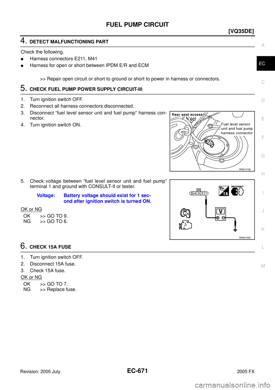
5. CHECK FUEL PUMP POWER SUPPLY CIRCUIT-III
1. Turn ignition switch OFF.
2. Reconnect all harness connectors disconnected.
3. Disconnect “fuel level sensor unit and fuel pump” harness con- nector.
4. Turn ignition switch ON.
5. Check voltage between “fuel level sensor unit and fuel pump” terminal 1 and ground with CONSULT-II or tester.
OK or NG
OK >> GO TO 9.
NG >> GO TO 6.
6. CHECK 15A FUSE
1. Turn ignition switch OFF.
2. Disconnect 15A fuse.
3. Check 15A fuse.
OK or NG
OK >> GO TO 7.
NG >> Replace fuse.
PBIB1572E
Voltage: Battery voltage should exist for 1 sec-
ond after ignition switch is turned ON.
PBIB0795E
Page 2065 of 4731
![INFINITI FX35 2005 Service Manual EC-672
[VQ35DE]
FUEL PUMP CIRCUIT
Revision: 2005 July 2005 FX
7. CHECK FUEL PUMP POWER SUPPLY CIRCUIT-IV
1. Disconnect IPDM E/R harness connector E8.
2. Check harness continuity between IPDM E/R ter](/manual-img/42/57020/w960_57020-2064.png "INFINITI FX35 2005 Service Manual EC-672
[VQ35DE]
FUEL PUMP CIRCUIT
Revision: 2005 July 2005 FX
7. CHECK FUEL PUMP POWER SUPPLY CIRCUIT-IV
1. Disconnect IPDM E/R harness connector E8.
2. Check harness continuity between IPDM E/R ter")
EC-672
[VQ35DE]
FUEL PUMP CIRCUIT
Revision: 2005 July 2005 FX
7. CHECK FUEL PUMP POWER SUPPLY CIRCUIT-IV
1. Disconnect IPDM E/R harness connector E8.
2. Check harness continuity between IPDM E/R terminal 39 and “fuel level sensor unit and fuel pump” termi- nal 1.
Refer to Wiring Diagram.
3. Also check harness for short to ground and short to power.
OK or NG
OK >> GO TO 11.
NG >> GO TO 8.
8. DETECT MALFUNCTIONING PART
Check the following.
�Harness connectors E206, B6
�Harness for open or short between IPDM E/R and “fuel level sensor unit and fuel pump”
>> Repair open circuit or short to ground or short to power in harness or connectors.
9. CHECK FUEL PUMP GROUND CIRCUIT FOR OPEN AND SHORT
1. Check harness continuity between “fuel level sensor unit and fuel pump” terminal 3 and ground. Refer to Wiring Diagram.
2. Also check harness for short to power.
OK or NG
OK >> GO TO 10.
NG >> Repair open circuit or short to power in harness or connectors.
10. CHECK FUEL PUMP
Refer to EC-1363, "
Component Inspection" .
OK or NG
OK >> GO TO 11.
NG >> Replace fuel pump.
11 . CHECK INTERMITTENT INCIDENT
Refer to EC-854, "
TROUBLE DIAGNOSIS FOR INTERMITTENT INCIDENT" .
OK or NG
OK >> Replace IPDM E/R.
NG >> Repair or replace harness or connectors.
Component InspectionABS006YJ
FUEL PUMP
1. Disconnect “fuel level sensor unit and fuel pump” harness connector. Continuity should exist.
Continuity should exist.
Page 2066 of 4731
FUEL PUMP CIRCUIT EC-673
[VQ35DE]
C
D E
F
G H
I
J
K L
M A
EC
Revision: 2005 July 2005 FX
2. Check resistance between “fuel level sensor unit and fuel pump”
terminals 1 and 3.
Removal and InstallationABS006YK
FUEL PUMP
Refer to FL-4, "FUEL LEVEL SENSOR UNIT, FUEL FILTER AND FUEL PUMP ASSEMBLY" .
Resistance: Approximately 0.2 - 5.0
Ω [at 25 °C
(77 °F)]
SEC918C
Page 2067 of 4731
EC-674
[VQ35DE]
REFRIGERANT PRESSURE SENSOR
Revision: 2005 July 2005 FX
REFRIGERANT PRESSURE SENSORPFP:92136
Component DescriptionABS006YL
The refrigerant pressure sensor is installed at the liquid tank of the
air conditioner system. The sensor uses an electrostatic volume
pressure transducer to convert refrigerant pressure to voltage. The
voltage signal is sent to ECM, and ECM controls cooling fan system.
PBIB2007E
SEF099XA
Page 2068 of 4731
REFRIGERANT PRESSURE SENSOR EC-675
[VQ35DE]
C
D E
F
G H
I
J
K L
M A
EC
Revision: 2005 July 2005 FX
Wiring DiagramABS006YM
TBWM0312E
Page 2069 of 4731
![INFINITI FX35 2005 Service Manual EC-676
[VQ35DE]
REFRIGERANT PRESSURE SENSOR
Revision: 2005 July 2005 FX
Specification data are reference values and are measured between each terminal and ground.
CAUTION:
Do not use ECM ground term](/manual-img/42/57020/w960_57020-2068.png "INFINITI FX35 2005 Service Manual EC-676
[VQ35DE]
REFRIGERANT PRESSURE SENSOR
Revision: 2005 July 2005 FX
Specification data are reference values and are measured between each terminal and ground.
CAUTION:
Do not use ECM ground term")
EC-676
[VQ35DE]
REFRIGERANT PRESSURE SENSOR
Revision: 2005 July 2005 FX
Specification data are reference values and are measured between each terminal and ground.
CAUTION:
Do not use ECM ground terminals when measuring input/output voltage. Doing so may result in dam-
age to the ECM's transistor. Use a ground other than ECM terminals, such as the ground.
Diagnostic ProcedureABS006YN
1. CHECK REFRIGERANT PRESSURE SENSOR OVERALL FUNCTION
1. Start engine and warm it up to normal operating temperature.
2. Turn A/C switch and blower switch ON.
3. Check voltage between ECM terminal 70 and ground with CON- SULT-II or tester.
OK or NG
OK >> INSPECTION END
NG >> GO TO 2.
2. CHECK GROUND CONNECTIONS
1. Turn A/C switch and blower switch OFF.
2. Stop engine.
3. Turn ignition switch OFF.
4. Loosen and retighten ground three screws on the body. Refer to EC-170, "
Ground Inspection" .
OK or NG
OK >> GO TO 3.
NG >> Repair or replace ground connections.
TER-
MINAL NO. WIRE
COLOR ITEM CONDITION DATA (DC Voltage)
49 PU Sensor power supply
(Refrigerant pressure sen-
sor) [Ignition switch: ON]
Approximately 5V
67 B/W Sensor ground [Engine is running]
�Warm-up condition
�Idle speed Approximately 0V
70 L/R Refrigerant pressure sensor [Engine is running]
�Warm-up condition
�Both A/C switch and blower switch are ON
(Compressor operates) 1.0 - 4.0V
Voltage: 1.0 - 4.0V
PBIB1188E
PBIB2625E
![INFINITI FX35 2005 Service Manual FUEL PUMP CIRCUIT EC-669
[VQ35DE]
C
D E
F
G H
I
J
K L
M A
EC
Revision: 2005 July 2005 FX
Wiring DiagramABS006YH
TBWM0737E](/manual-img/42/57020/w960_57020-2061.png "INFINITI FX35 2005 Service Manual FUEL PUMP CIRCUIT EC-669
[VQ35DE]
C
D E
F
G H
I
J
K L
M A
EC
Revision: 2005 July 2005 FX
Wiring DiagramABS006YH
TBWM0737E")
![INFINITI FX35 2005 Service Manual FUEL PUMP CIRCUIT EC-673
[VQ35DE]
C
D E
F
G H
I
J
K L
M A
EC
Revision: 2005 July 2005 FX
2. Check resistance between “fuel level sensor unit and fuel pump”
terminals 1 and 3.
Removal](/manual-img/42/57020/w960_57020-2065.png "INFINITI FX35 2005 Service Manual FUEL PUMP CIRCUIT EC-673
[VQ35DE]
C
D E
F
G H
I
J
K L
M A
EC
Revision: 2005 July 2005 FX
2. Check resistance between “fuel level sensor unit and fuel pump”
terminals 1 and 3.
Removal")
![INFINITI FX35 2005 Service Manual EC-674
[VQ35DE]
REFRIGERANT PRESSURE SENSOR
Revision: 2005 July 2005 FX
REFRIGERANT PRESSURE SENSORPFP:92136
Component DescriptionABS006YL
The refrigerant pressure sensor is installed at the liquid ta](/manual-img/42/57020/w960_57020-2066.png "INFINITI FX35 2005 Service Manual EC-674
[VQ35DE]
REFRIGERANT PRESSURE SENSOR
Revision: 2005 July 2005 FX
REFRIGERANT PRESSURE SENSORPFP:92136
Component DescriptionABS006YL
The refrigerant pressure sensor is installed at the liquid ta")
![INFINITI FX35 2005 Service Manual REFRIGERANT PRESSURE SENSOR EC-675
[VQ35DE]
C
D E
F
G H
I
J
K L
M A
EC
Revision: 2005 July 2005 FX
Wiring DiagramABS006YM
TBWM0312E](/manual-img/42/57020/w960_57020-2067.png "INFINITI FX35 2005 Service Manual REFRIGERANT PRESSURE SENSOR EC-675
[VQ35DE]
C
D E
F
G H
I
J
K L
M A
EC
Revision: 2005 July 2005 FX
Wiring DiagramABS006YM
TBWM0312E")