Page 373 of 4731
AT-290
DISASSEMBLY
Revision: 2005 July 2005 FX
DISASSEMBLYPFP:31020
DisassemblyACS0081L
CAUTION:
Do not disassemble parts behind Drum Support. Refer to AT- 1 8 , "
Cross-Sectional View (2WD Models)"
or AT- 1 9 , "Cross-Sectional View (AWD Models)" .
1. Drain ATF through drain plug.
2. Remove torque converter by holding it firmly and turing while pulling straight out.
3. Check torque converter one-way clutch using check tool as shown in the figure.
a. Insert check tool into the groove of bearing support built into one-way clutch outer race.
b. When fixing bearing support with check tool, rotate one-way clutch spline using screwdriver.
c. Make sure that inner race rotates clockwise only. If not, replace torque converter assembly.
4. Remove converter housing from transmission case. CAUTION:
Be careful not to scratch converter housing.
SCIA5010E
SCIA3171E
SCIA3427E
Page 376 of 4731
DISASSEMBLY AT-293
D E
F
G H
I
J
K L
M A
B
AT
Revision: 2005 July 2005 FX
14. Loosen lock nut and remove band servo anchor end pin from
transmission case.
15. Remove brake band from transmission case.
�To prevent brake linings from cracking or peeling, do not
stretch the flexible band unnecessarily. When removing
the brake band, always secure it with a clip as shown in
the figure at right.
Leave the clip in position after removing the brake band.
�Check brake band facing for damage, cracks, wear or
burns.
16. Remove mid carrier assembly and rear carrier assembly as a unit.
17. Remove mid carrier assembly from rear carrier assembly.
SCIA6512E
SCIA2580E
SAT655
SCIA5017E
SCIA5697E
Page 395 of 4731
AT-312
REPAIR FOR COMPONENT PARTS
Revision: 2005 July 2005 FX
INSPECTION
3rd One-way Clutch
�Check frictional surface for wear or damage.
CAUTION:
If necessary, replace the 3rd one-way clutch.
Front Sun Gear Snap Ring
�Check for deformation, fatigue or damage.
CAUTION:
If necessary, replace the snap ring.
Front Sun Gear
�Check for deformation, fatigue or damage.
CAUTION:
If necessary, replace the front sun gear.
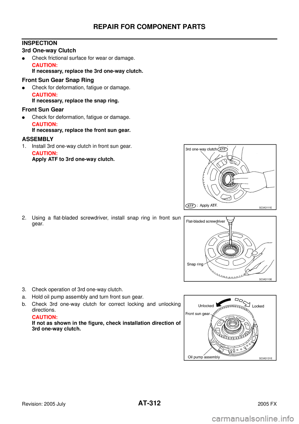
ASSEMBLY
1. Install 3rd one-way clutch in front sun gear.
CAUTION:
Apply ATF to 3rd one-way clutch.
2. Using a flat-bladed screwdriver, install snap ring in front sun gear.
3. Check operation of 3rd one-way clutch.
a. Hold oil pump assembly and turn front sun gear.
b. Check 3rd one-way clutch for correct locking and unlocking directions.
CAUTION:
If not as shown in the figure, check installation direction of
3rd one-way clutch.
S C I A 3 111 E
SCIA3110E
SCIA3131E
Page 405 of 4731
AT-322
REPAIR FOR COMPONENT PARTS
Revision: 2005 July 2005 FX
5. Install needle bearing to high and low reverse clutch hub.
CAUTION:
Apply petroleum jelly to needle bearing.
6. Install high and low reverse clutch hub to mid sun gear assem- bly.
7. Using snap ring pliers, install snap ring to mid sun gear assem- bly.
CAUTION:
Do not expand snap ring excessively.
8. Check operation of 1st one-way clutch.
a. Hold mid sun gear and turn rear sun gear.
b. Check 1st one-way clutch for correct locking and unlocking directions.
CAUTION:
If not as shown in the figure, check installation direction of
1st one-way clutch.
9. Install needle bearing and bearing race to high and low reverse clutch hub.
CAUTION:
Apply petroleum jelly to needle bearing and bearing race.
SCIA2857E
SCIA2856E
SCIA2855E
SCIA3132E
SCIA2854E
Page 423 of 4731
AT-340
ASSEMBLY
Revision: 2005 July 2005 FX
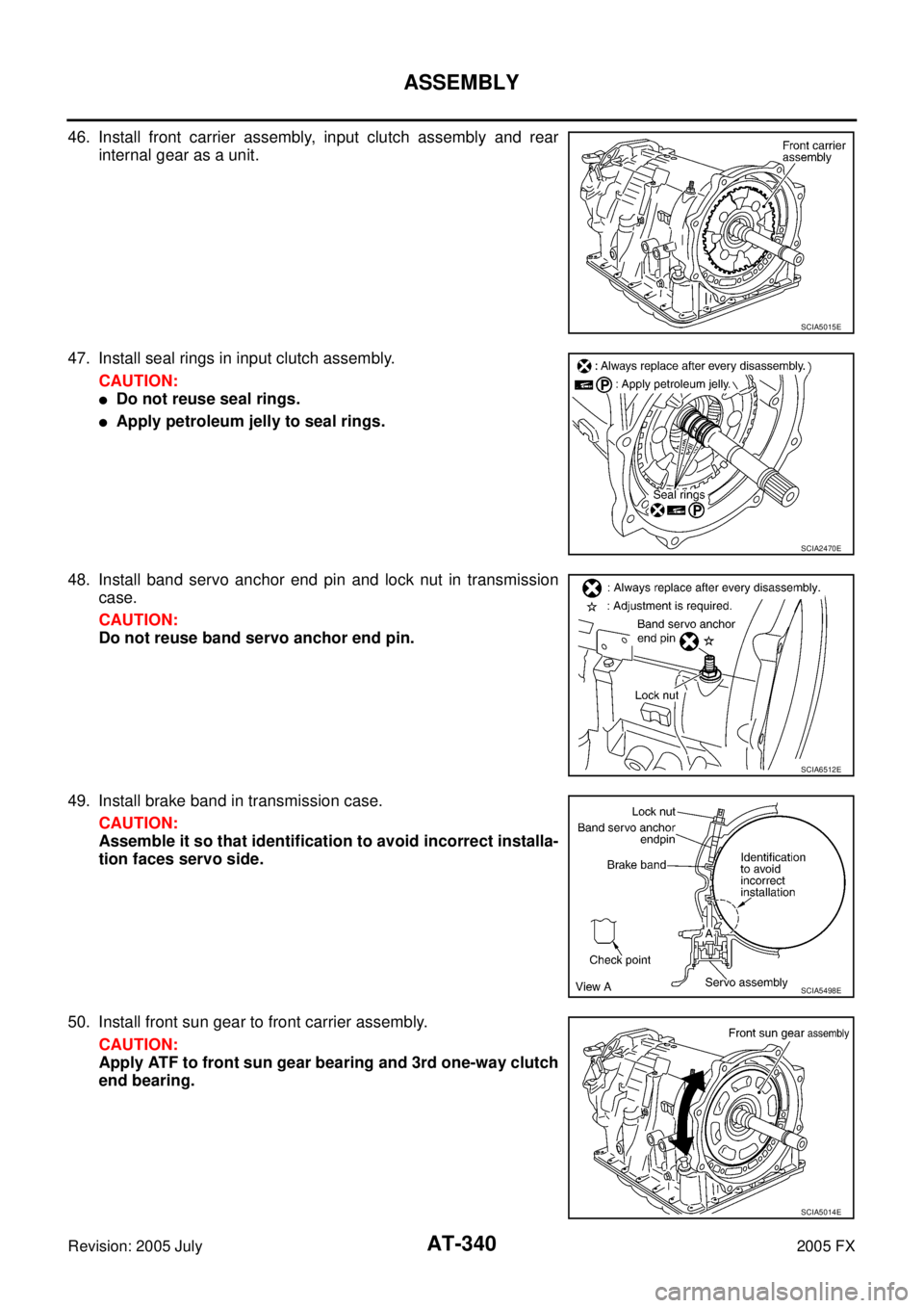
46. Install front carrier assembly, input clutch assembly and rear
internal gear as a unit.
47. Install seal rings in input clutch assembly. CAUTION:
�Do not reuse seal rings.
�Apply petroleum jelly to seal rings.
48. Install band servo anchor end pin and lock nut in transmission case.
CAUTION:
Do not reuse band servo anchor end pin.
49. Install brake band in transmission case. CAUTION:
Assemble it so that identification to avoid incorrect installa-
tion faces servo side.
50. Install front sun gear to front carrier assembly. CAUTION:
Apply ATF to front sun gear bearing and 3rd one-way clutch
end bearing.
SCIA5015E
SCIA2470E
SCIA6512E
SCIA5498E
SCIA5014E
Page 424 of 4731
ASSEMBLY AT-341
D E
F
G H
I
J
K L
M A
B
AT
Revision: 2005 July 2005 FX
51. Install needle bearing to front sun gear.
CAUTION:
Apply petroleum jelly to needle bearing.
52. Adjust brake band tilting using clips so that brake band contacts front sun gear drum evenly.
53. Adjust brake band.
a. Loosen lock nut.
b. Tighten band servo anchor end pin to specified torque.
c. Back of band servo anchor end pin three turns.
d. Holding band servo anchor end pin, tighten lock nut to specified torque.
AdjustmentACS0081T
TOTAL END PLAY
�Measure clearance between front sun gear and bearing race for
oil pump cover.
�Select proper thickness of bearing race so that end play is within
specifications.
SCIA2808E
SCIA5033E
: 5.0 N·m (0.51 kg-m, 44 in-lb)
: 46 N·m (4.7 kg-m, 34 ft-lb)
SCIA5498E
SCIA2810E
Page 435 of 4731

Revision: 2005 July 2005 FX
Vehicle Speed at Which Lock-up Occurs/ReleasesACS002S4
2WD MODELS
�At closed throttle, the accelerator opening is less than 1/8")
AT-352
SERVICE DATA AND SPECIFICATIONS (SDS)
Revision: 2005 July 2005 FX
Vehicle Speed at Which Lock-up Occurs/ReleasesACS002S4
2WD MODELS
�At closed throttle, the accelerator opening is less than 1/8 condition. (Closed throttle position signal: OFF)
�At half throttle, the accelerator opening is 4/8 of the full opening.
AW D M OD E LS
�At closed throttle, the accelerator opening is less than 1/8 condition. (Closed throttle position signal: OFF)
�At half throttle, the accelerator opening is 4/8 of the full opening.
�At closed throttle, the accelerator opening is less than 1/8 condition. (Closed throttle position signal: OFF)
�At half throttle, the accelerator opening is 4/8 of the full opening.
Stall SpeedACS002S6
Line PressureACS002S7
A/T Fluid Temperature SensorACS00858
Engine model VQ35DE
Throttle position Vehicle speed km/h (MPH)
Lock-up ON Lock-up OFF
Closed throttle 65 - 73 (40 - 45) 62 - 70 (39 - 43)
Half throttle 196 - 204 (122 - 127) 153 - 161 (95 - 100)
Engine model VQ35DE
Throttle position Vehicle speed km/h (MPH)
Lock-up ON Lock-up OFF
Closed throttle 59 - 67 (37 - 42) 56 - 64 (35 - 40)
Half throttle 178 - 186 (111 - 116) 139 - 147 (86 - 91)
Engine model VK45DE
Throttle position Vehicle speed km/h (MPH)
Lock-up ON Lock-up OFF
Closed throttle 66 - 74 (41 - 46) 53 - 61 (33 - 38)
Half throttle 191 - 199 (119 - 124) 136 - 144 (85 - 89)
Engine model VQ35DE
Stall speed 2,200 - 2,400 rpm
Engine model VK45DE
Stall speed 1,950 - 2,250 rpm
Engine speed Line pressure [kPa (kg/cm2 , psi)]
R position D and M positions
At idle speed 425 - 465 (4.3 - 4.8, 62 - 67) 379 - 428 (3.9 - 4.4, 55 - 62)
At stall speed 1,605 - 1,950 (16.4 - 19.9, 233 - 283) 1,310 - 1,500 (13.4 - 15.3, 190 - 218)
Name Condition CONSULT-II “DATA MONITOR” (Approx.) (V) Resistance (Approx.) (k Ω)
A/T fluid temperature sensor 1 0
°C (32 °F) 3.3 15
20 °C (68 °F) 2.7 6.5
80 °C (176 °F) 0.9 0.9
A/T fluid temperature sensor 2 0
°C (32 °F) 3.3 10
20 °C (68 °F) 2.5 4
80 °C (176 °F) 0.7 0.5
Page 442 of 4731
 “AIR BAG” and “SEAT
BELT PRE-TE")
PRECAUTIONS ATC-5
C
D E
F
G H
I
K L
M A
B
AT C
Revision: 2005 July 2005 FX
PRECAUTIONSPFP:00001
Precautions for Supplemental Restraint System (SRS) “AIR BAG” and “SEAT
BELT PRE-TENSIONER”
AJS001XF
The Supplemental Restraint System such as “AIR BAG” and “SEAT BELT PRE-TENSIONER”, used along
with a front seat belt, helps to reduce the risk or severity of injury to the driver and front passenger for certain
types of collision. This system includes seat belt switch inputs and dual stage front air bag modules. The SRS
system uses the seat belt switches to determine the front air bag deployment, and may only deploy one front
air bag, depending on the severity of a collision and whether the front occupants are belted or unbelted.
Information necessary to service the system safely is included in the SRS and SB section of this Service Man-
ual.
WARNING:
�To avoid rendering the SRS inoperative, which could increase the risk of personal injury or death
in the event of a collision which would result in air bag inflation, all maintenance must be per-
formed by an authorized NISSAN/INFINITI dealer.
�Improper maintenance, including incorrect removal and installation of the SRS, can lead to per-
sonal injury caused by unintentional activation of the system. For removal of Spiral Cable and Air
Bag Module, see the SRS section.
�Do not use electrical test equipment on any circuit related to the SRS unless instructed to in this
Service Manual. SRS wiring harnesses can be identified by yellow and/or orange harnesses or
harness connectors.
Precautions Necessary for Steering Wheel Rotation After Battery DisconnectAJS001XG
NOTE:
�This Procedure is applied only to models with Intelligent Key system and NVIS/IVIS (NISSAN/INFINITI
VEHICLE IMMOBILIZER SYSTEM - NATS).
�Remove and install all control units after disconnecting both battery cables with the ignition knob in the
″ LOCK ″ position.
�Always use CONSULT-II to perform self-diagnosis as a part of each function inspection after finishing
work. If DTC is detected, perform trouble diagnosis according to self-diagnostic results.
For models equipped with the Intelligent Key system and NVIS/IVIS, an electrically controlled steering lock
mechanism is adopted on the key cylinder.
For this reason, if the battery is disconnected or if the battery is discharged, the steering wheel will lock and
steering wheel rotation will become impossible.
If steering wheel rotation is required when battery power is interrupted, follow the procedure below before
starting the repair operation.
OPERATION PROCEDURE
1. Connect both battery cables.
NOTE:
Supply power using jumper cables if battery is discharged.
2. Use the Intelligent Key or mechanical key to turn the ignition switch to the ″ACC ″ position. At this time, the
steering lock will be released.
3. Disconnect both battery cables. The steering lock will remain released and the steering wheel can be rotated.
4. Perform the necessary repair operation.
5. When the repair work is completed, return the ignition switch to the ″LOCK ″ position before connecting
the battery cables. (At this time, the steering lock mechanism will engage.)
6. Perform a self-diagnosis check of all control units using CONSULT-II.