Page 4167 of 4731

MA-40
SERVICE DATA AND SPECIFICATIONS (SDS)
Revision: 2005 July 2005 FX
SERVICE DATA AND SPECIFICATIONS (SDS)PFP:00030
Standard and LimitALS000G0
BELT DEFLECTION AND TENSION (VQ35DE)
*: If belt tension gauge cannot be installed at check points shown, check drive belt tension at different location on the belt.
BELT DEFLECTION AND TENSION (VK45DE)
ENGINE COOLANT CAPACITY (APPROXIMATE) (VQ35DE)
Unit: (US qt, lmp qt)
ENGINE COOLANT CAPACITY (APPROXIMATE) (VK45DE)
Unit: (US qt, lmp qt)
RADIATOR
Unit: kPa (kg/cm2 , psi)
ENGINE OIL CAPACITY (APPROXIMATE) (VQ35DE)
Unit: (US qt, lmp qt)
Deflection adjustment Unit: mm (in) Tension adjustment* Unit: N (kg, lb)
Used belt New belt Used belt
New belt
Limit After adjustment Limit After adjustment
Alternator and
power steering
oil pump belt 7 (0.28)
4 - 5
(0.16 - 0.20) 3.5 - 4.5
(0.138 - 0.177) 294 (30, 66) 730 - 818
(74.5 - 83.5,
164 - 184) 838 - 926
(85.5 - 94.5,
188 - 208)
A/C compressor
belt 12 (0.47)9 - 10
(0.35 - 0.39) 8 - 9
(0.31 - 0.35) 196 (20, 44) 348 - 436
(35.5 - 44.5, 78 - 98) 470 - 559
(48 - 57,
106 - 126)
Applied pushing
force 98 N (10 kg, 22 lb) —
KBIA1731J
Tension of drive belts Auto-adjustment by auto tensioner
Engine coolant capacity (With reservoir tank at “MAX” level) 8.6 (9-1/8, 7-5/8)
Reservoir tank engine coolant capacity (At “MAX” level) 0.8 (7/8, 3/4)
Engine coolant capacity (With reservoir tank at “MAX” level) 10.0 (10-5/8, 8-3/4)
Reservoir tank engine coolant capacity (At “MAX” level) 0.8 (7/8, 3/4)
Cap relief pressure Standard 78 - 98 (0.8 - 1.0, 11 - 14)
Limit 59 (0.6, 9)
Leakage testing pressure 157 (1.6, 23)
Drain and refill With oil filter change 4.7 (5, 4-1/8)
Without oil filter change 4.4 (4-5/8, 3-7/8)
Dry engine (Overhaul) 5.4 (5-3/4, 4-3/4)
Page 4197 of 4731
PG-20
IPDM E/R (INTELLIGENT POWER DISTRIBUTION MODULE ENGINE ROOM)
Revision: 2005 July 2005 FX
CONSULT-II Function (IPDM E/R)AKS005SC
CONSULT-II can display each diagnostic item using the diagnostic test mode shown following.
CONSULT-II INSPECTION PROCEDURE
CAUTION:
If CONSULT-II is used with no connection of CONSULT-II CONVERTER, malfunctions might be
detected in self-diagnosis depending on control unit which carry out CAN communication.
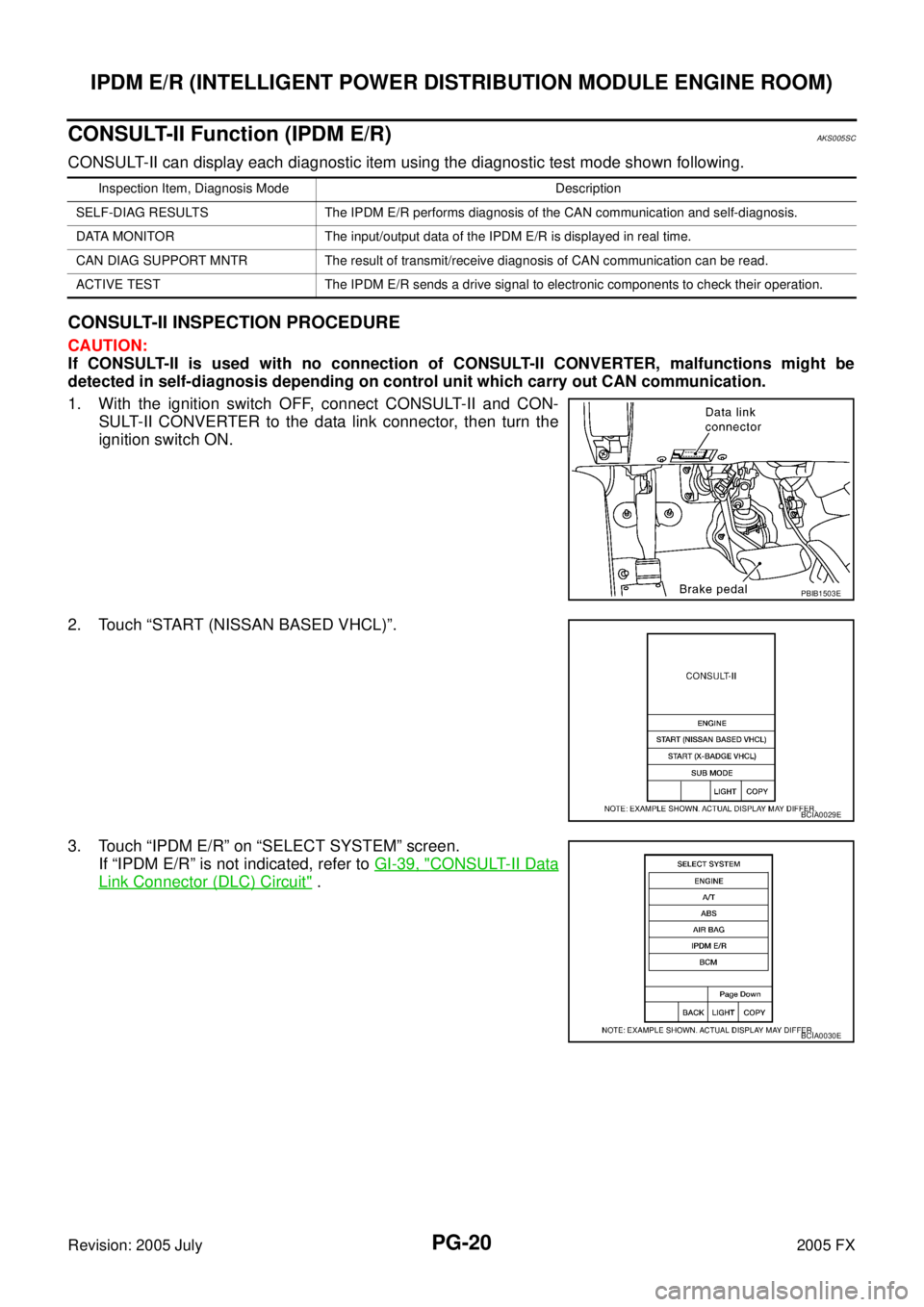
1. With the ignition switch OFF, connect CONSULT-II and CON- SULT-II CONVERTER to the data link connector, then turn the
ignition switch ON.
2. Touch “START (NISSAN BASED VHCL)”.
3. Touch “IPDM E/R” on “SELECT SYSTEM” screen. If “IPDM E/R” is not indicated, refer to GI-39, "
CONSULT-II Data
Link Connector (DLC) Circuit" .
Inspection Item, Diagnosis Mode Description
SELF-DIAG RESULTS The IPDM E/R performs diagnosis of the CAN communication and self-diagnosis.
DATA MONITOR The input/output data of the IPDM E/R is displayed in real time.
CAN DIAG SUPPORT MNTR The result of transmit/receive diagnosis of CAN communication can be read.
ACTIVE TEST The IPDM E/R sends a drive signal to electronic components to check their operation.
PBIB1503E
BCIA0029E
BCIA0030E
Page 4198 of 4731
IPDM E/R (INTELLIGENT POWER DISTRIBUTION MODULE ENGINE ROOM) PG-21
C
D E
F
G H
I
J
L
M A
B
PG
Revision: 2005 July 2005 FX
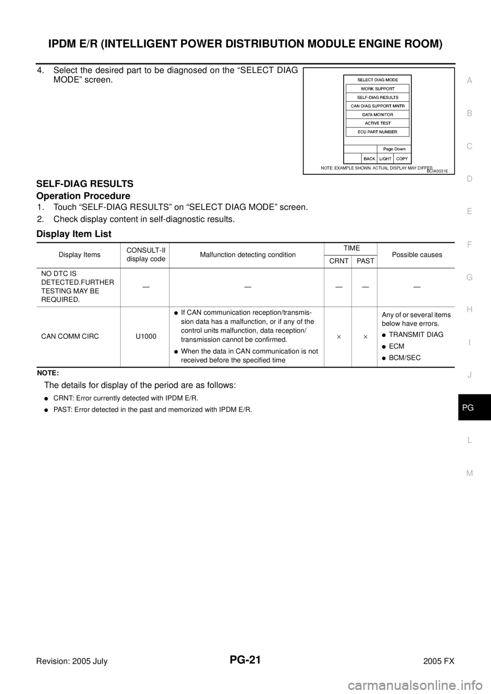
4. Select the desired part to be diagnosed on the “SELECT DIAG
MODE” screen.
SELF-DIAG RESULTS
Operation Procedure
1. Touch “SELF-DIAG RESULTS” on “SELECT DIAG MODE” screen.
2. Check display content in self-diagnostic results.
Display Item List
NOTE:
The details for display of the period are as follows:
�CRNT: Error currently detected with IPDM E/R.
�PAST: Error detected in the past and memorized with IPDM E/R.
BCIA0031E
Display Items CONSULT-II
display code Malfunction detecting condition TIME
Possible causes
CRNT PAST
NO DTC IS
DETECTED.FURTHER
TESTING MAY BE
REQUIRED. —————
CAN COMM CIRC U1000
�If CAN communication reception/transmis-
sion data has a malfunction, or if any of the
control units malfunction, data reception/
transmission cannot be confirmed.
�When the data in CAN communication is not
received before the specified time ××
Any of or several items
below have errors.
�TRANSMIT DIAG
�ECM
�BCM/SEC
Page 4201 of 4731
PG-24
IPDM E/R (INTELLIGENT POWER DISTRIBUTION MODULE ENGINE ROOM)
Revision: 2005 July 2005 FX
Auto Active TestAKS005SD
DESCRIPTION
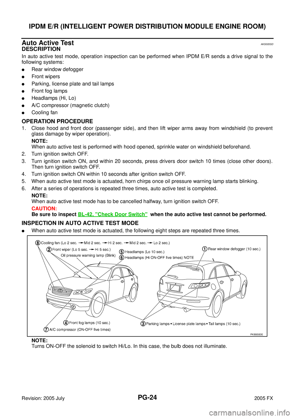
In auto active test mode, operation inspection can be performed when IPDM E/R sends a drive signal to the
following systems:
�Rear window defogger
�Front wipers
�Parking, license plate and tail lamps
�Front fog lamps
�Headlamps (Hi, Lo)
�A/C compressor (magnetic clutch)
�Cooling fan
OPERATION PROCEDURE
1. Close hood and front door (passenger side), and then lift wiper arms away from windshield (to prevent glass damage by wiper operation).
NOTE:
When auto active test is performed with hood opened, sprinkle water on windshield beforehand.
2. Turn ignition switch OFF.
3. Turn ignition switch ON, and within 20 seconds, press drivers door switch 10 times (close other doors). Then turn ignition switch OFF.
4. Turn ignition switch ON within 10 seconds after ignition switch OFF.
5. When auto active test mode is actuated, horn chirps once oil pressure warning lamp starts blinking.
6. After a series of operations is repeated three times, auto active test is completed. NOTE:
When auto active test mode has to be cancelled halfway, turn ignition switch OFF.
CAUTION:
Be sure to inspect BL-42, "
Check Door Switch" when the auto active test cannot be performed.
INSPECTION IN AUTO ACTIVE TEST MODE
�When auto active test mode is actuated, the following eight steps are repeated three times.
NOTE:
Turns ON-OFF the solenoid to switch Hi/Lo. In this case, the bulb does not illuminate.
PKIB6583E
Page 4205 of 4731
PG-28
IPDM E/R (INTELLIGENT POWER DISTRIBUTION MODULE ENGINE ROOM)
Revision: 2005 July 2005 FX
IPDM E/R Power/Ground Circuit InspectionAKS007NW
1. CHECK FUSE AND FUSIBLE LINK
Make sure the following fusible links or IPDM E/R fuses are not blown.
OK or NG
OK >> GO TO 2.
NG >> If fuse or fusible link blown, be sure to eliminate cause of malfunction before installing new one.
2. CHECK POWER SUPPLY CIRCUIT
1. Turn ignition switch OFF.
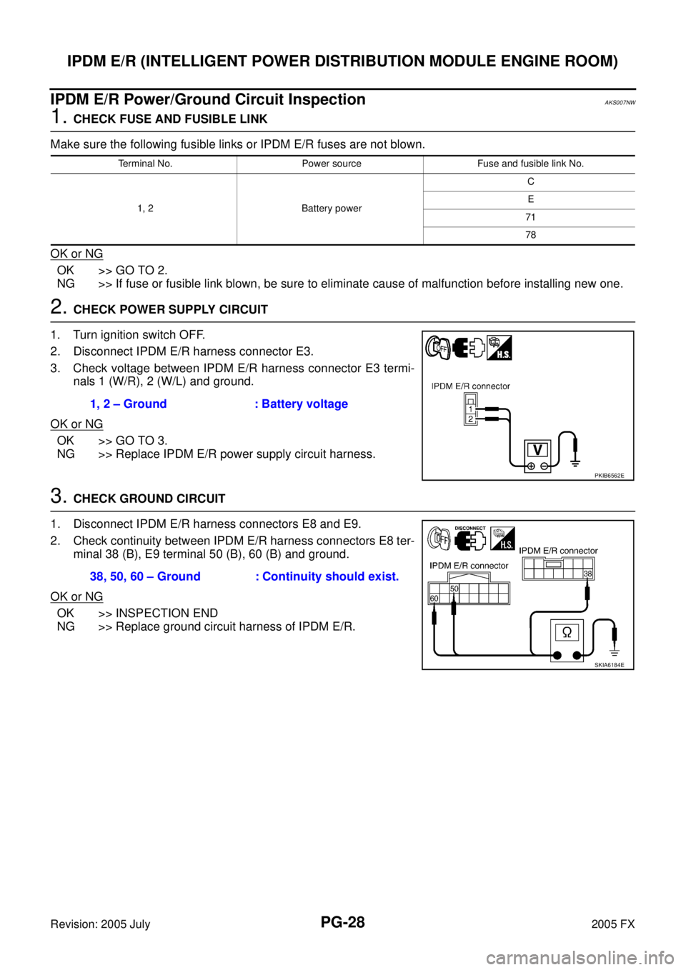
2. Disconnect IPDM E/R harness connector E3.
3. Check voltage between IPDM E/R harness connector E3 termi- nals 1 (W/R), 2 (W/L) and ground.
OK or NG
OK >> GO TO 3.
NG >> Replace IPDM E/R power supply circuit harness.
3. CHECK GROUND CIRCUIT
1. Disconnect IPDM E/R harness connectors E8 and E9.
2. Check continuity between IPDM E/R harness connectors E8 ter- minal 38 (B), E9 terminal 50 (B), 60 (B) and ground.
OK or NG
OK >> INSPECTION END
NG >> Replace ground circuit harness of IPDM E/R.
Terminal No. Power source Fuse and fusible link No.
1, 2 Battery power C
E
71
78
1, 2 – Ground : Battery voltage
PKIB6562E
38, 50, 60 – Ground : Continuity should exist.
SKIA6184E
Page 4206 of 4731
IPDM E/R (INTELLIGENT POWER DISTRIBUTION MODULE ENGINE ROOM) PG-29
C
D E
F
G H
I
J
L
M A
B
PG
Revision: 2005 July 2005 FX
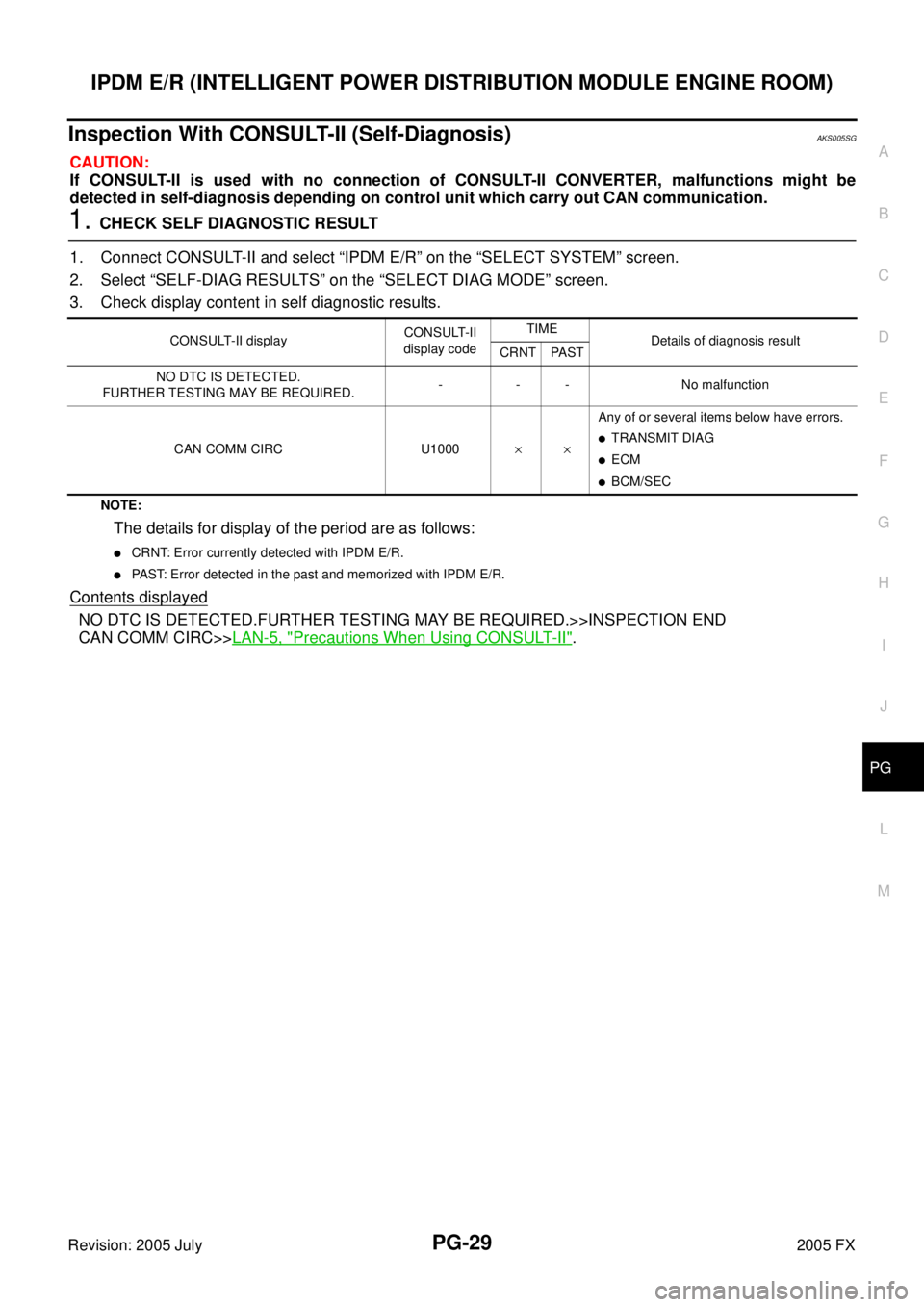
Inspection With CONSULT-II (Self-Diagnosis)AKS005SG
CAUTION:
If CONSULT-II is used with no connection of CONSULT-II CONVERTER, malfunctions might be
detected in self-diagnosis depending on control unit which carry out CAN communication.
1. CHECK SELF DIAGNOSTIC RESULT
1. Connect CONSULT-II and select “IPDM E/R” on the “SELECT SYSTEM” screen.
2. Select “SELF-DIAG RESULTS” on the “SELECT DIAG MODE” screen.
3. Check display content in self diagnostic results.
NOTE:
The details for display of the period are as follows:
�CRNT: Error currently detected with IPDM E/R.
�PAST: Error detected in the past and memorized with IPDM E/R.
Contents displayed
NO DTC IS DETECTED.FURTHER TESTING MAY BE REQUIRED.>>INSPECTION END
CAN COMM CIRC>> LAN-5, "
Precautions When Using CONSULT-II".
CONSULT-II display CONSULT-II
display code TIME
Details of diagnosis result
CRNT PAST
NO DTC IS DETECTED.
FURTHER TESTING MAY BE REQUIRED. - - - No malfunction
CAN COMM CIRC U1000 ×× Any of or several items below have errors.
�TRANSMIT DIAG
�ECM
�BCM/SEC
Page 4283 of 4731
PS-8
POWER STEERING FLUID
Revision: 2005 July 2005 FX
POWER STEERING FLUIDPFP:KLF20
Checking Fluid LevelAGS000GT
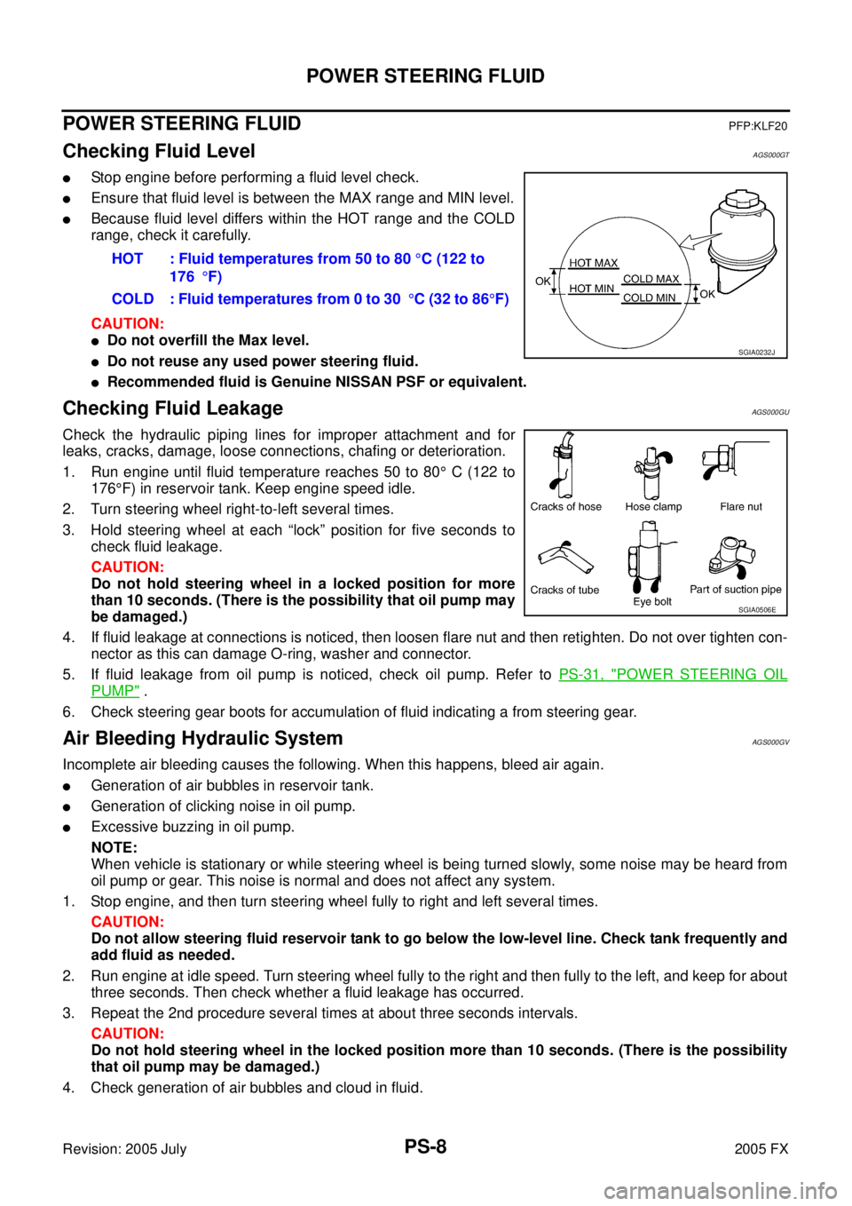
�Stop engine before performing a fluid level check.
�Ensure that fluid level is between the MAX range and MIN level.
�Because fluid level differs within the HOT range and the COLD
range, check it carefully.
CAUTION:
�Do not overfill the Max level.
�Do not reuse any used power steering fluid.
�Recommended fluid is Genuine NISSAN PSF or equivalent.
Checking Fluid LeakageAGS000GU
Check the hydraulic piping lines for improper attachment and for
leaks, cracks, damage, loose connections, chafing or deterioration.
1. Run engine until fluid temperature reaches 50 to 80 ° C (122 to
176 °F) in reservoir tank. Keep engine speed idle.
2. Turn steering wheel right-to-left several times.
3. Hold steering wheel at each “lock” position for five seconds to check fluid leakage.
CAUTION:
Do not hold steering wheel in a locked position for more
than 10 seconds. (There is the possibility that oil pump may
be damaged.)
4. If fluid leakage at connections is noticed, then loosen flare nut and then retighten. Do not over tighten con- nector as this can damage O-ring, washer and connector.
5. If fluid leakage from oil pump is noticed, check oil pump. Refer to PS-31, "
POWER STEERING OIL
PUMP" .
6. Check steering gear boots for accumulation of fluid indicating a from steering gear.
Air Bleeding Hydraulic SystemAGS000GV
Incomplete air bleeding causes the following. When this happens, bleed air again.
�Generation of air bubbles in reservoir tank.
�Generation of clicking noise in oil pump.
�Excessive buzzing in oil pump.
NOTE:
When vehicle is stationary or while steering wheel is being turned slowly, some noise may be heard from
oil pump or gear. This noise is normal and does not affect any system.
1. Stop engine, and then turn steering wheel fully to right and left several times. CAUTION:
Do not allow steering fluid reservoir tank to go below the low-level line. Check tank frequently and
add fluid as needed.
2. Run engine at idle speed. Turn steering wheel fully to the right and then fully to the left, and keep for about three seconds. Then check whether a fluid leakage has occurred.
3. Repeat the 2nd procedure several times at about three seconds intervals. CAUTION:
Do not hold steering wheel in the locked position more than 10 seconds. (There is the possibility
that oil pump may be damaged.)
4. Check generation of air bubbles and cloud in fluid. HOT : Fluid temperatures from 50 to 80
°C (122 to
176 °F)
COLD : Fluid temperatures from 0 to 30 °C (32 to 86 °F)
SGIA0232J
SGIA0506E
Page 4284 of 4731
POWER STEERING FLUID PS-9
C
D E
F
H I
J
K L
M A
B
PS
Revision: 2005 July 2005 FX
5. If air bubbles and the cloud don't fade, stop engine, hold air bleeding until air bubbles and the cloud fade.
Perform the 2nd and the 3rd procedures again.
6. Stop engine, check fluid level.