Page 359 of 4731

AT-276
TRANSMISSION ASSEMBLY
Revision: 2005 July 2005 FX
24. Remove transmission assembly with transfer from vehicle.
�Secure torque converter to prevent it from dropping.
�Secure transmission assembly to a jack.
25. Remove transfer from transmission assembly. Refer to TF-44,
"Removal and Installation" .
INSPECTION
Installation and Inspection of Torque Converter
�After inserting a torque converter to a transmission, be sure to
check distance “A” to ensure it is within the reference value limit.
INSTALLATION
Install the removed parts in the reverse order of the removal, while paying attention to the following work.
�When installing transmission assembly to the engine assembly, attach the fixing bolts in accordance with
the following standard.
For VQ35DE models
For VK45DE models
*: No.2 bolt also secures A/T fluid charging pipe.
SCIA2203E
Distance “A”
VQ35DE models: 25.0 mm (0.98 in) or more
VK45DE models: 22.0 mm (0.87 in) or more
SAT017B
Bolt No. 1 2 3 4
Number of bolts 1 5 2 1
Bolt length
“ ”mm (in) 55 (2.17) 65 (2.56) 35 (1.38) 40 (1.57)
Tightening torque
N·m (kg-m, ft-lb) 75
(7.7, 55) 47
(4.8, 35) 34
(3.5, 25)
SCIA4600E
Bolt No. 1 2* 3
Number of bolts 5 1 4
Bolt length
“ ”mm (in) 70 (2.76) 70 (2.76) 65 (2.56)
Tightening torque
N·m (kg-m, ft-lb) 11 3
(12, 83) 74.0
(7.5, 55)
SCIA4601E
Page 360 of 4731

TRANSMISSION ASSEMBLY AT-277
D E
F
G H
I
J
K L
M A
B
AT
Revision: 2005 July 2005 FX
�Align the positions of tightening bolts for drive plate with those of
the torque converter, and temporarily tighten the bolts. Then,
tighten the bolts with the specified torque. Refer to AT- 2 7 3 ,
"COMPONENTS (FOR VQ35DE)" or AT- 2 7 4 , "COMPONENTS
(FOR VK45DE)" .
CAUTION:
�When turning crankshaft, turn it clockwise as viewed from
the front of the engine.
�When tightening the tightening bolts for the torque con-
verter after fixing the crankshaft pulley bolts, be sure to
confirm the tightening torque of the crankshaft pulley
mounting bolts.
�After converter is installed to drive plate, rotate crankshaft several turns and check to be sure that
transmission rotates freely without binding.
�Install crankshaft position sensor (POS). Refer to EM-30, "Removal and Installation (2WD Model)" , EM-
185, "Removal and Installation" .
�After completing installation, check A/T fluid leakage, A/T fluid level, and the positions of A/T. Refer to AT-
12, "Changing A/T Fluid" , AT- 2 3 5 , "Adjustment of A/T Position" , AT- 2 3 5 , "Checking of A/T Position" .
SCIA2010E
Page 362 of 4731
OVERHAUL AT-279
D E
F
G H
I
J
K L
M A
B
AT
Revision: 2005 July 2005 FX
1. O-ring 2. Oil pump cover 3. O-ring
4. Oil pump housing 5. Self-sealing bolt 6. Torque converter
7. Converter housing 8. Oil pump housing oil seal 9. Bearing race
10. Needle bearing 11. O-ring 12. Front carrier assembly
13. Snap ring 14. Front sun gear 15. 3rd one-way clutch
16. Snap ring 17. Bearing race 18. Needle bearing
19. Seal ring 20. Input clutch assembly 21. Needle bearing
22. Rear internal gear 23. Brake band 24. Mid carrier assembly
25. Needle bearing 26. Bearing race 27. Rear carrier assembly
28. Needle bearing 29. Mid sun gear 30. Seal ring
31. Rear sun gear 32. 1st one-way clutch 33. Snap ring
34. Needle bearing 35. High and low reverse clutch hub 36. Snap ring
37. Bearing race 38. Needle bearing
Page 373 of 4731
AT-290
DISASSEMBLY
Revision: 2005 July 2005 FX
DISASSEMBLYPFP:31020
DisassemblyACS0081L
CAUTION:
Do not disassemble parts behind Drum Support. Refer to AT- 1 8 , "
Cross-Sectional View (2WD Models)"
or AT- 1 9 , "Cross-Sectional View (AWD Models)" .
1. Drain ATF through drain plug.
2. Remove torque converter by holding it firmly and turing while pulling straight out.
3. Check torque converter one-way clutch using check tool as shown in the figure.
a. Insert check tool into the groove of bearing support built into one-way clutch outer race.
b. When fixing bearing support with check tool, rotate one-way clutch spline using screwdriver.
c. Make sure that inner race rotates clockwise only. If not, replace torque converter assembly.
4. Remove converter housing from transmission case. CAUTION:
Be careful not to scratch converter housing.
SCIA5010E
SCIA3171E
SCIA3427E
Page 393 of 4731
AT-310
REPAIR FOR COMPONENT PARTS
Revision: 2005 July 2005 FX
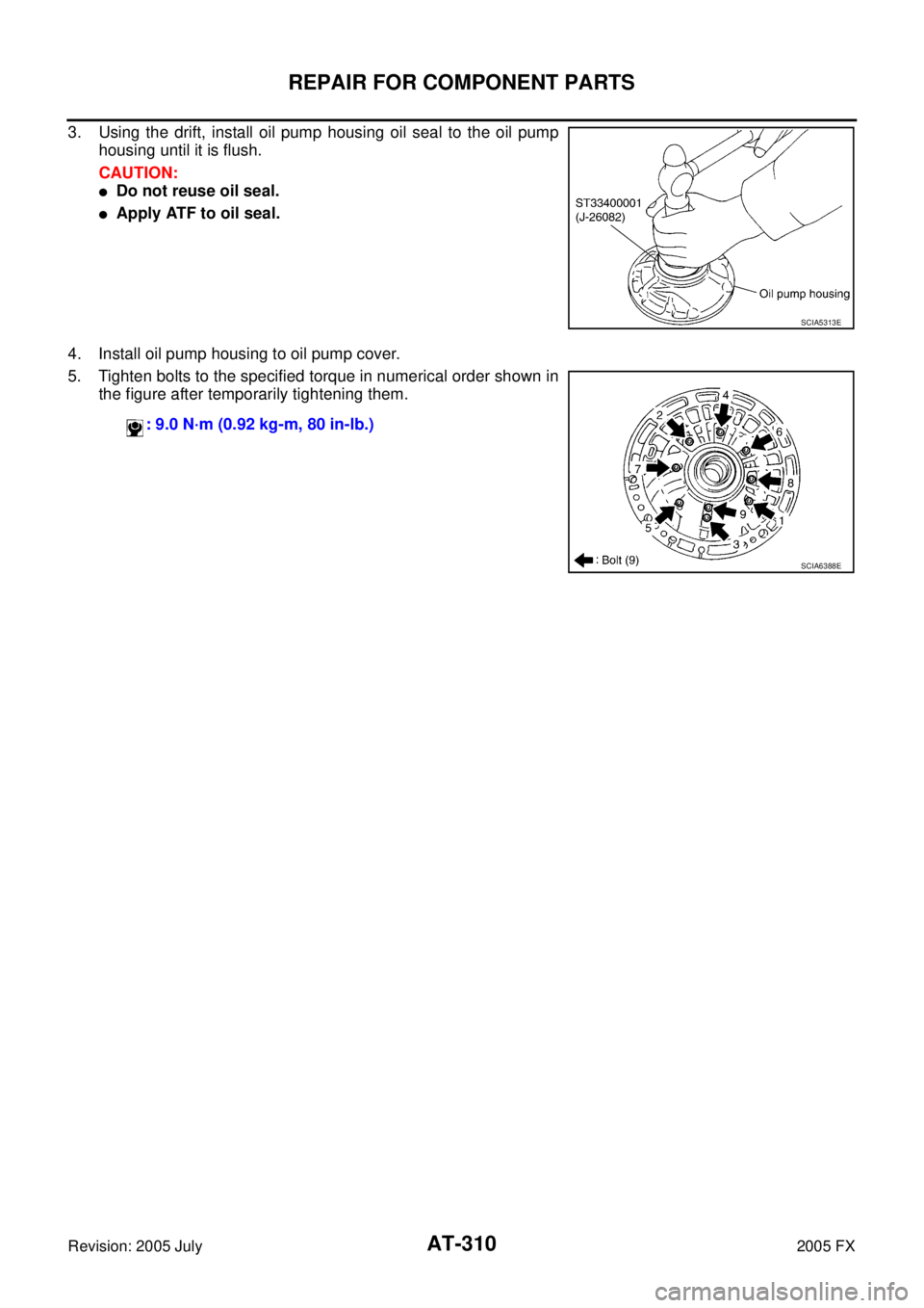
3. Using the drift, install oil pump housing oil seal to the oil pump
housing until it is flush.
CAUTION:
�Do not reuse oil seal.
�Apply ATF to oil seal.
4. Install oil pump housing to oil pump cover.
5. Tighten bolts to the specified torque in numerical order shown in the figure after temporarily tightening them.
SCIA5313E
: 9.0 N·m (0.92 kg-m, 80 in-lb.)
SCIA6388E
Page 419 of 4731
AT-336
ASSEMBLY
Revision: 2005 July 2005 FX
ii. Install rear extension assembly to transmission case.
CAUTION:
Insert the tip of parking rod between the parking pawl and
the parking actuator support when assembling the rear
extension assembly.
iii. Tighten rear extension assembly mounting bolts to specified torque.
CAUTION:
Do not reuse self-sealing bolt.
b. AW D m o d e l s
i. Install gasket onto transmission case. CAUTION:
�Completely remove all moisture, oil and old gasket, etc.
from the transmission case and adapter case assembly
mounting surfaces.
�Do not reuse gasket.
ii. Install adapter case assembly to transmission case. CAUTION:
Insert the tip of parking rod between the parking pawl and
the parking actuator support when assembling the rear
extension assembly.
SCIA5029E
Rear extension assembly mounting bolt:
: 52 N·m (5.3 kg-m, 38 ft-lb)
Self-sealing bolt: : 61 N·m (6.2 kg-m, 45 ft-lb)
SCIA6941E
SCIA5231E
SCIA5186E
Page 420 of 4731
ASSEMBLY AT-337
D E
F
G H
I
J
K L
M A
B
AT
Revision: 2005 July 2005 FX
iii. Tighten adapter case assembly mounting bolts (1) to specified
torque. [With bracket (2).]
: Bolt (10)
CAUTION:
Do not reuse self-sealing bolts (3).
Refer to GI section to mark sure icons (symbol marks) in the fig-
ure. Refer to GI-10, "
Components" .
35. Install needle bearing in drum support. CAUTION:
Apply petroleum jelly to needle bearing.
36. Install direct clutch assembly in reverse brake. CAUTION:
Make sure that drum support edge surface and direct clutch
inner boss edge surface come to almost same place.
37. Install high and low reverse clutch assembly in direct clutch. Adapter case assembly mounting bolt:
: 52 N·m (5.3 kg-m, 38 ft-lb)
Self-sealing bolt: : 61 N·m (6.2 kg-m, 45 ft-lb)
SCIA7210E
SCIA5198E
SCIA5019E
SCIA2306E
Page 424 of 4731
ASSEMBLY AT-341
D E
F
G H
I
J
K L
M A
B
AT
Revision: 2005 July 2005 FX
51. Install needle bearing to front sun gear.
CAUTION:
Apply petroleum jelly to needle bearing.
52. Adjust brake band tilting using clips so that brake band contacts front sun gear drum evenly.
53. Adjust brake band.
a. Loosen lock nut.
b. Tighten band servo anchor end pin to specified torque.
c. Back of band servo anchor end pin three turns.
d. Holding band servo anchor end pin, tighten lock nut to specified torque.
AdjustmentACS0081T
TOTAL END PLAY
�Measure clearance between front sun gear and bearing race for
oil pump cover.
�Select proper thickness of bearing race so that end play is within
specifications.
SCIA2808E
SCIA5033E
: 5.0 N·m (0.51 kg-m, 44 in-lb)
: 46 N·m (4.7 kg-m, 34 ft-lb)
SCIA5498E
SCIA2810E


![INFINITI FX35 2005 Service Manual ASSEMBLY AT-337
D E
F
G H
I
J
K L
M A
B
AT
Revision: 2005 July 2005 FX
iii. Tighten adapter case assembly mounting bolts (1) to specified
torque. [With bracket (2).]
: Bolt (10)
CAUTION](/manual-img/42/57020/w960_57020-419.png "INFINITI FX35 2005 Service Manual ASSEMBLY AT-337
D E
F
G H
I
J
K L
M A
B
AT
Revision: 2005 July 2005 FX
iii. Tighten adapter case assembly mounting bolts (1) to specified
torque. [With bracket (2).]
: Bolt (10)
CAUTION")
