Page 4294 of 4731
POWER STEERING GEAR AND LINKAGE PS-19
C
D E
F
H I
J
K L
M A
B
PS
Revision: 2005 July 2005 FX
POWER STEERING GEAR AND LINKAGEPFP:49001
Removal and InstallationAGS000H0
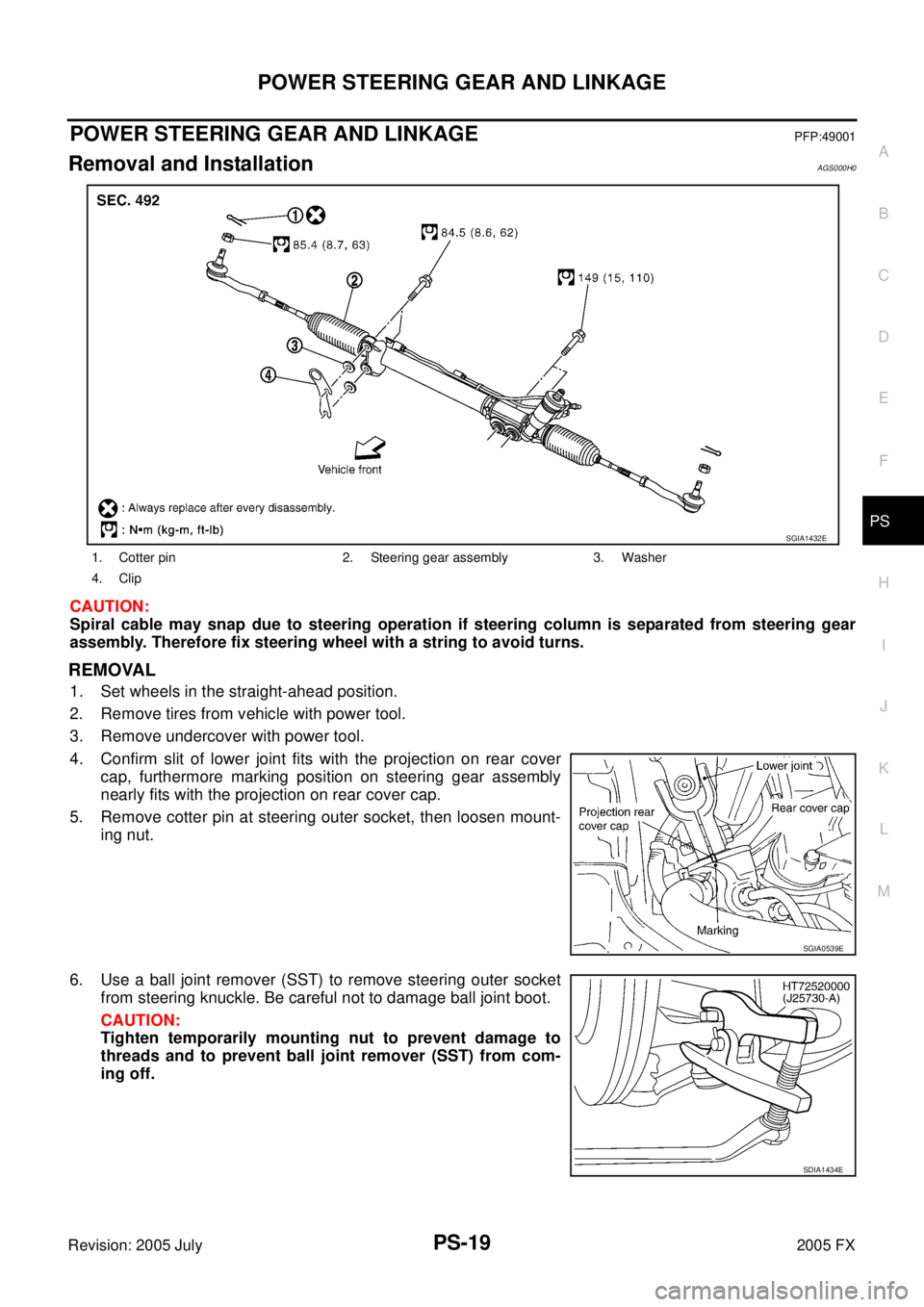
CAUTION:
Spiral cable may snap due to steering operation if steering column is separated from steering gear
assembly. Therefore fix steering wheel with a string to avoid turns.
REMOVAL
1. Set wheels in the straight-ahead position.
2. Remove tires from vehicle with power tool.
3. Remove undercover with power tool.
4. Confirm slit of lower joint fits with the projection on rear cover cap, furthermore marking position on steering gear assembly
nearly fits with the projection on rear cover cap.
5. Remove cotter pin at steering outer socket, then loosen mount- ing nut.
6. Use a ball joint remover (SST) to remove steering outer socket from steering knuckle. Be careful not to damage ball joint boot.
CAUTION:
Tighten temporarily mounting nut to prevent damage to
threads and to prevent ball joint remover (SST) from com-
ing off.
1. Cotter pin 2. Steering gear assembly 3. Washer
4. Clip
SGIA1432E
SGIA0539E
SDIA1434E
Page 4298 of 4731
POWER STEERING GEAR AND LINKAGE PS-23
C
D E
F
H I
J
K L
M A
B
PS
Revision: 2005 July 2005 FX
CAUTION:
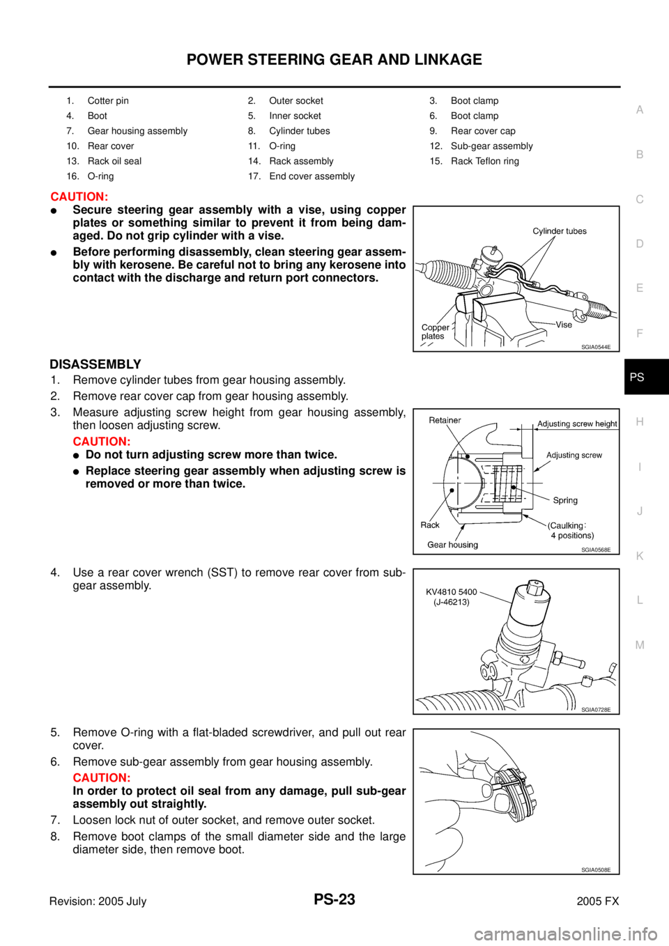
�Secure steering gear assembly with a vise, using copper
plates or something similar to prevent it from being dam-
aged. Do not grip cylinder with a vise.
�Before performing disassembly, clean steering gear assem-
bly with kerosene. Be careful not to bring any kerosene into
contact with the discharge and return port connectors.
DISASSEMBLY
1. Remove cylinder tubes from gear housing assembly.
2. Remove rear cover cap from gear housing assembly.
3. Measure adjusting screw height from gear housing assembly, then loosen adjusting screw.
CAUTION:
�Do not turn adjusting screw more than twice.
�Replace steering gear assembly when adjusting screw is
removed or more than twice.
4. Use a rear cover wrench (SST) to remove rear cover from sub- gear assembly.
5. Remove O-ring with a flat-bladed screwdriver, and pull out rear cover.
6. Remove sub-gear assembly from gear housing assembly. CAUTION:
In order to protect oil seal from any damage, pull sub-gear
assembly out straightly.
7. Loosen lock nut of outer socket, and remove outer socket.
8. Remove boot clamps of the small diameter side and the large diameter side, then remove boot.
1. Cotter pin 2. Outer socket 3. Boot clamp
4. Boot 5. Inner socket 6. Boot clamp
7. Gear housing assembly 8. Cylinder tubes 9. Rear cover cap
10. Rear cover 11. O-ring 12. Sub-gear assembly
13. Rack oil seal 14. Rack assembly 15. Rack Teflon ring
16. O-ring 17. End cover assembly
SGIA0544E
SGIA0568E
SGIA0728E
SGIA0508E
Page 4299 of 4731
PS-24
POWER STEERING GEAR AND LINKAGE
Revision: 2005 July 2005 FX
CAUTION:
When removing boots, be careful not to damage inner socket and gear housing assembly. If they
are damaged, change them to avoid oil leaks.
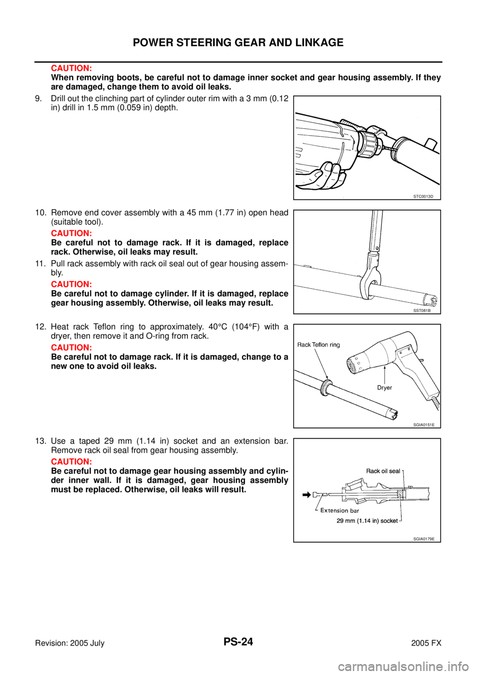
9. Drill out the clinching part of cylinder outer rim with a 3 mm (0.12 in) drill in 1.5 mm (0.059 in) depth.
10. Remove end cover assembly with a 45 mm (1.77 in) open head (suitable tool).
CAUTION:
Be careful not to damage rack. If it is damaged, replace
rack. Otherwise, oil leaks may result.
11. Pull rack assembly with rack oil seal out of gear housing assem- bly.
CAUTION:
Be careful not to damage cylinder. If it is damaged, replace
gear housing assembly. Otherwise, oil leaks may result.
12. Heat rack Teflon ring to approximately. 40 °C (104 °F) with a
dryer, then remove it and O-ring from rack.
CAUTION:
Be careful not to damage rack. If it is damaged, change to a
new one to avoid oil leaks.
13. Use a taped 29 mm (1.14 in) socket and an extension bar. Remove rack oil seal from gear housing assembly.
CAUTION:
Be careful not to damage gear housing assembly and cylin-
der inner wall. If it is damaged, gear housing assembly
must be replaced. Otherwise, oil leaks will result.
STC0013D
SST081B
SGIA0151E
SGIA0179E
Page 4300 of 4731
POWER STEERING GEAR AND LINKAGE PS-25
C
D E
F
H I
J
K L
M A
B
PS
Revision: 2005 July 2005 FX
INSPECTION AFTER DISASSEMBLY
Boot
Check boot for cracks and deformation. Replace it, if necessary.
Rack
Check rack for damage and wear. Replace it, if necessary.
Sub-Gear Assembly
�Check pinion gear for damage and wear. Replace it, if necessary.
�Check bearing while rotating it. Replace bearing if bearing ball race was dented, worn, or damaged.
Gear Housing Assembly
Check gear housing assembly for damage and scratches (inner wall). Replace it, if necessary.
Outer Socket and Inner Socket
Swing Torque
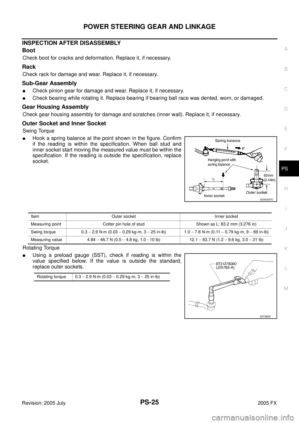
�Hook a spring balance at the point shown in the figure. Confirm
if the reading is within the specification. When ball stud and
inner socket start moving the measured value must be within the
specification. If the reading is outside the specification, replace
socket.
Rotating Torque
�Using a preload gauge (SST), check if reading is within the
value specified below. If the value is outside the standard,
replace outer sockets.
SGIA0547E
Item Outer socket Inner socket
Measuring point Cotter pin hole of stud Shown as L: 83.2 mm (3.276 in)
Swing torque 0.3 − 2.9 N·m (0.03 − 0.29 kg-m, 3 − 25 in-lb) 1.0 − 7.8 N·m (0.11 − 0.79 kg-m, 9 − 69 in-lb)
Measuring value 4.84 − 46.7 N (0.5 − 4.8 kg, 1.0 - 10 lb) 12.1 − 93.7 N (1.2 − 9.6 kg, 3.0 − 21 lb)
Rotating torque 0.3 − 2.9 N·m (0.03 − 0.29 kg-m, 3 − 25 in-lb)
SST882B
Page 4304 of 4731
POWER STEERING GEAR AND LINKAGE PS-29
C
D E
F
H I
J
K L
M A
B
PS
Revision: 2005 July 2005 FX
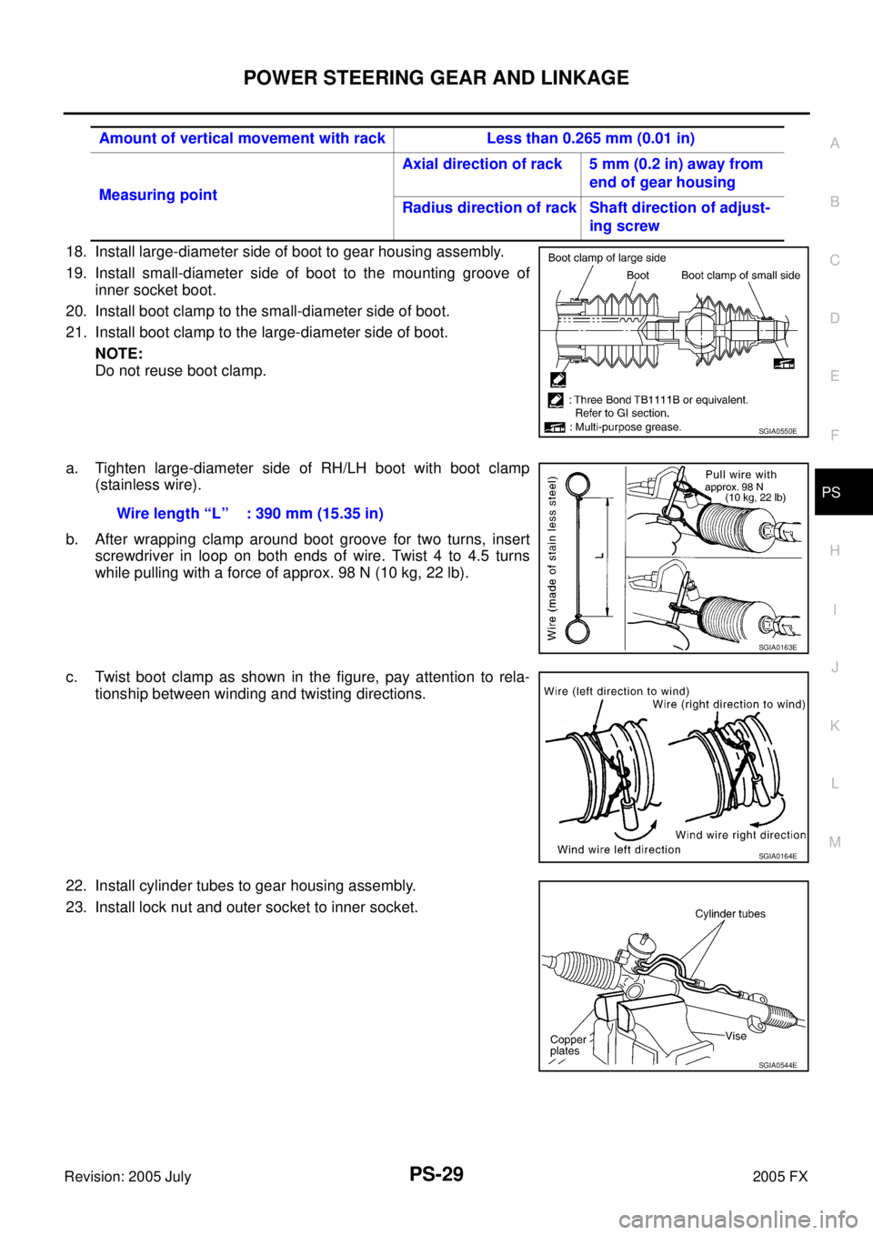
18. Install large-diameter side of boot to gear housing assembly.
19. Install small-diameter side of boot to the mounting groove of inner socket boot.
20. Install boot clamp to the small-diameter side of boot.
21. Install boot clamp to the large-diameter side of boot.
NOTE:
Do not reuse boot clamp.
a. Tighten large-diameter side of RH/LH boot with boot clamp (stainless wire).
b. After wrapping clamp around boot groove for two turns, insert screwdriver in loop on both ends of wire. Twist 4 to 4.5 turns
while pulling with a force of approx. 98 N (10 kg, 22 lb).
c. Twist boot clamp as shown in the figure, pay attention to rela- tionship between winding and twisting directions.
22. Install cylinder tubes to gear housing assembly.
23. Install lock nut and outer socket to inner socket. Amount of vertical movement with rack Less than 0.265 mm (0.01 in)
Measuring point Axial direction of rack 5 mm (0.2 in) away from
end of gear housing
Radius direction of rack Shaft direction of adjust- ing screw
SGIA0550E
Wire length “L” : 390 mm (15.35 in)
SGIA0163E
SGIA0164E
SGIA0544E
Page 4329 of 4731
RAX-6
WHEEL HUB
Revision: 2005 July 2005 FX
10. Loosen fixing bolts and nuts of front lower link, radius rod, and rear lower link in side of suspension mem-
ber.
11. Set jack under rear lower link. Then remove fixing bolt in front lower link side of shock absorber with power tool.
12. Remove bolt and nut in axle side of rear lower link with power tool. Then remove coil spring. Refer to RSU-15, "
REAR LOWER LINK & COIL SPRING" .
13. Remove fixing bolts and nuts in axle side of front lower link, radius rod with power tool.
14. Remove suspension arm and cotter pin at axle, then loosen mounting nut.
15. Use a ball joint remover (suitable tool) to remove suspension arm from axle. Be careful not to damage ball joint boot.
CAUTION:
Tighten temporarily mounting nut to prevent damage to threads and to prevent ball joint remover
(suitable tool) from coming off.
16. Remove axle from vehicle.
INSPECTION AFTER REMOVAL
Ball Joint Inspection
Check for boot breakage, axial looseness, and torque of suspension arm ball joint. Refer to RSU-11,
"INSPECTION AFTER REMOVAL" .
INSTALLATION
�Refer to RAX-5, "Removal and Installation" for tightening torque. Install in the reverse order of removal.
NOTE:
Refer to component parts location and do not reuse non-reusable parts.
�Perform final tightening of installation position of suspension links (rubber bushing) under unladen condi-
tions with tires on level ground, Check wheel alignment. Refer to RSU-5, "
Wheel Alignment Inspection" .
�After adjusting wheel alignment, adjust neutral position of steering angle sensor. Refer to BRC-6, "Adjust-
ment of Steering Angle Sensor Neutral Position" .
Disassembly and AssemblyADS000C6
DISASSEMBLY
Wheel Bearing
CAUTION:
Do not disassemble if wheel bearing has no trouble.
1. Remove wheel bearing fixing bolts and anchor block fixing nuts, and remove wheel hub and bearing assembly, back plate and anchor block from axle.
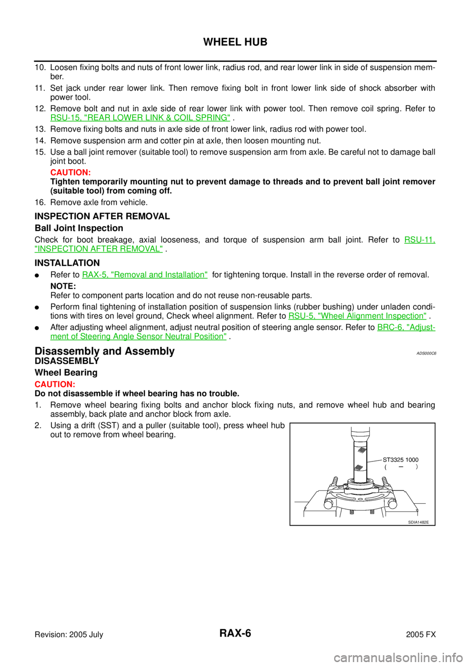
2. Using a drift (SST) and a puller (suitable tool), press wheel hub out to remove from wheel bearing.
SDIA1482E
Page 4332 of 4731
REAR DRIVE SHAFT RAX-9
C E F
G H
I
J
K L
M A
B
RAX
Revision: 2005 July 2005 FX
REAR DRIVE SHAFTPFP:39600
Removal and InstallationADS000C7
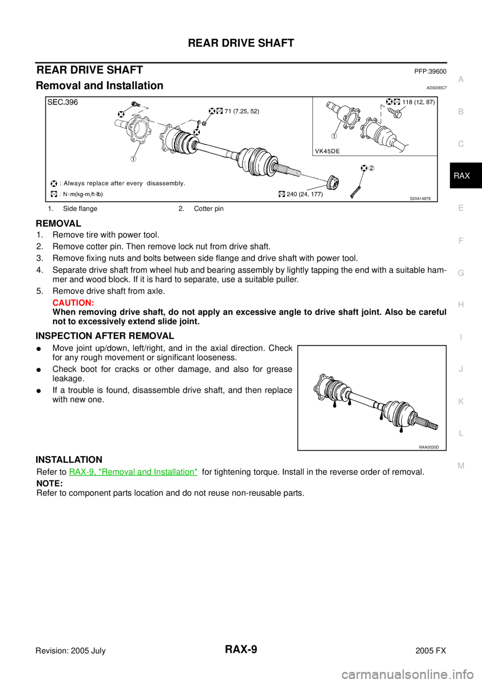
REMOVAL
1. Remove tire with power tool.
2. Remove cotter pin. Then remove lock nut from drive shaft.
3. Remove fixing nuts and bolts between side flange and drive shaft with power tool.
4. Separate drive shaft from wheel hub and bearing assembly by lightly tapping the end with a suitable ham- mer and wood block. If it is hard to separate, use a suitable puller.
5. Remove drive shaft from axle. CAUTION:
When removing drive shaft, do not apply an excessive angle to drive shaft joint. Also be careful
not to excessively extend slide joint.
INSPECTION AFTER REMOVAL
�Move joint up/down, left/right, and in the axial direction. Check
for any rough movement or significant looseness.
�Check boot for cracks or other damage, and also for grease
leakage.
�If a trouble is found, disassemble drive shaft, and then replace
with new one.
INSTALLATION
Refer to RAX-9, "Removal and Installation" for tightening torque. Install in the reverse order of removal.
NOTE:
Refer to component parts location and do not reuse non-reusable parts.
1. Side flange 2. Cotter pin
SDIA1487E
RAA0030D
Page 4333 of 4731
RAX-10
REAR DRIVE SHAFT
Revision: 2005 July 2005 FX
Disassembly and AssemblyADS000C8
DISASSEMBLY
Final Drive Side
1. Press shaft in a vice.
CAUTION:
When retaining drive shaft in a vise, always use copper or aluminum plates between vise and
shaft.
2. Remove boot bands.
3. If plug needs to be removed, move boot to wheel side, and drive it out with a plastic hammer.
4. Remove stopper ring with a flat-bladed screwdriver, and pull out housing.
5. Remove snap ring, then remove ball cage/steel ball/inner race assembly from shaft.
6. Remove boot from shaft.
7. Remove old grease on housing with paper towels.
1. Plug 2. Housing 3. Snap ring
4. Ball cage/Steel ball/Inner race assembly 5. Stopper ring 6. Boot band
7. Boot 8. Shaft 9. Circular clip
10. Joint sub-assembly
SDIA1488E
SRA249A
SFA514A