Page 4022 of 4731
PARKING, LICENSE PLATE AND TAIL LAMPS LT-133
C
D E
F
G H
I
J
L
M A
B
LT
Revision: 2005 July 2005 FX
Wiring Diagram — TAIL/L —AKS007DX
TKWM0821E
Page 4028 of 4731

PARKING, LICENSE PLATE AND TAIL LAMPS LT-139
C
D E
F
G H
I
J
L
M A
B
LT
Revision: 2005 July 2005 FX
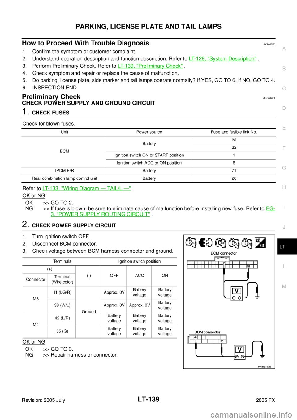
How to Proceed With Trouble DiagnosisAKS007E0
1. Confirm the symptom or customer complaint.
2. Understand operation description and function description. Refer to LT- 1 2 9 , "
System Description" .
3. Perform Preliminary Check. Refer to LT- 1 3 9 , "
Preliminary Check" .
4. Check symptom and repair or replace the cause of malfunction.
5. Do parking, license plate, side marker and tail lamps operate normally? If YES, GO TO 6. If NO, GO TO 4.
6. INSPECTION END
Preliminary CheckAKS007E1
CHECK POWER SUPPLY AND GROUND CIRCUIT
1. CHECK FUSES
Check for blown fuses.
Refer to LT- 1 3 3 , "
Wiring Diagram — TAIL/L —" .
OK or NG
OK >> GO TO 2.
NG >> If fuse is blown, be sure to eliminate cause of malfunction before installing new fuse. Refer to PG-
3, "POWER SUPPLY ROUTING CIRCUIT" .
2. CHECK POWER SUPPLY CIRCUIT
1. Turn ignition switch OFF.
2. Disconnect BCM connector.
3. Check voltage between BCM harness connector and ground.
OK or NG
OK >> GO TO 3.
NG >> Repair harness or connector.
Unit Power source Fuse and fusible link No.
BCM Battery
M
22
Ignition switch ON or START position 1 Ignition switch ACC or ON position 6
IPDM E/R Battery 71
Rear combination lamp control unit Battery 20
Terminals Ignition switch position
(+) (-) OFF ACC ON
Connector Terminal
(Wire color)
M3 11 (LG/R)
Ground Approx. 0V
Battery
voltage Battery
voltage
38 (W/L) Approx. 0V Approx. 0V Battery
voltage
M4 42 (L/R)
Battery
voltage Battery
voltage Battery
voltage
55 (G) Battery
voltage Battery
voltage Battery
voltage
PKIB5197E
Page 4056 of 4731
INTERIOR ROOM LAMP LT-167
C
D E
F
G H
I
J
L
M A
B
LT
Revision: 2005 July 2005 FX
Wiring Diagram — ROOM/L —AKS007FA
TKWM2047E
Page 4065 of 4731

LT-176
INTERIOR ROOM LAMP
Revision: 2005 July 2005 FX
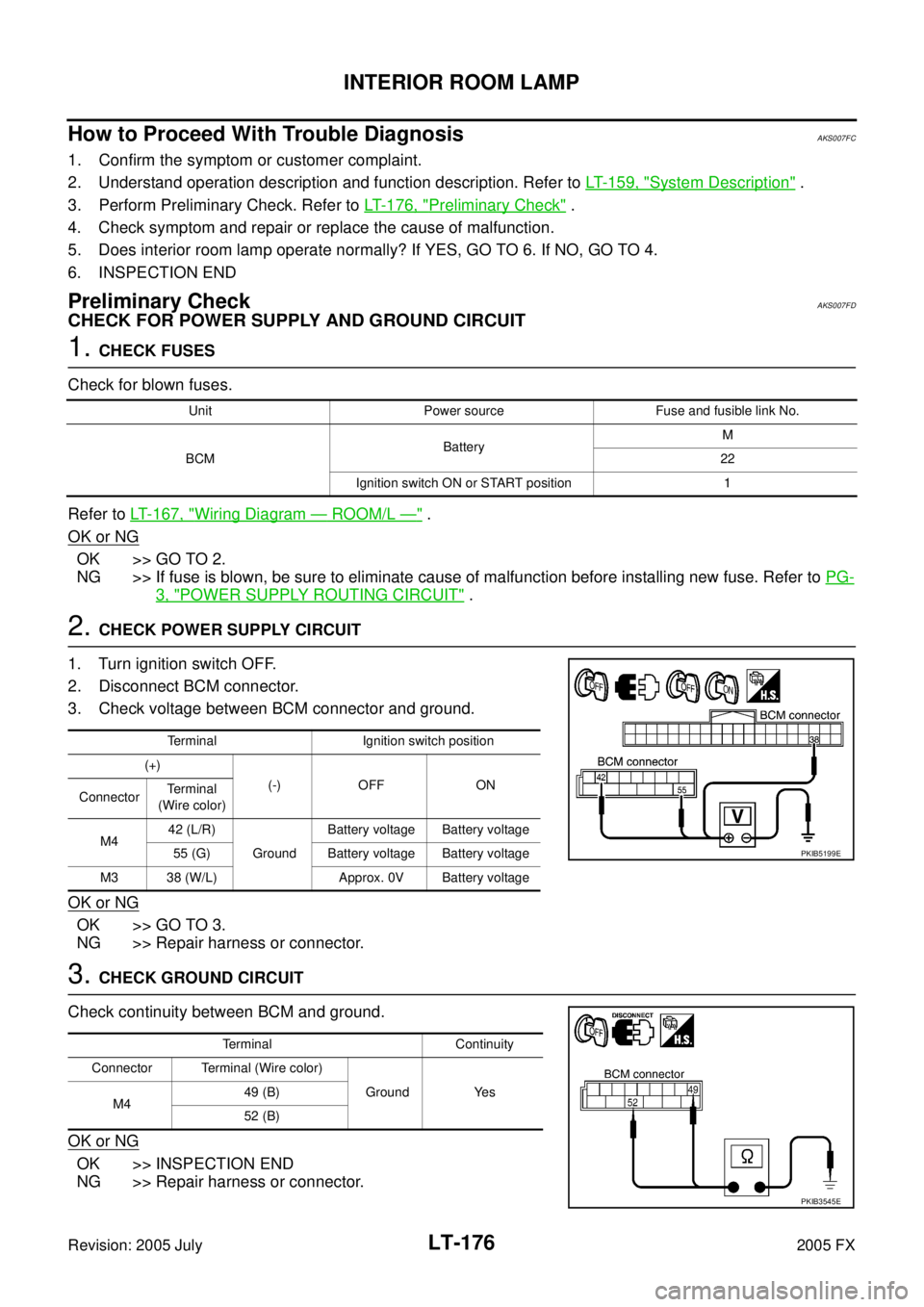
How to Proceed With Trouble DiagnosisAKS007FC
1. Confirm the symptom or customer complaint.
2. Understand operation description and function description. Refer to LT- 1 5 9 , "
System Description" .
3. Perform Preliminary Check. Refer to LT- 1 7 6 , "
Preliminary Check" .
4. Check symptom and repair or replace the cause of malfunction.
5. Does interior room lamp operate normally? If YES, GO TO 6. If NO, GO TO 4.
6. INSPECTION END
Preliminary CheckAKS007FD
CHECK FOR POWER SUPPLY AND GROUND CIRCUIT
1. CHECK FUSES
Check for blown fuses.
Refer to LT- 1 6 7 , "
Wiring Diagram — ROOM/L —" .
OK or NG
OK >> GO TO 2.
NG >> If fuse is blown, be sure to eliminate cause of malfunction before installing new fuse. Refer to PG-
3, "POWER SUPPLY ROUTING CIRCUIT" .
2. CHECK POWER SUPPLY CIRCUIT
1. Turn ignition switch OFF.
2. Disconnect BCM connector.
3. Check voltage between BCM connector and ground.
OK or NG
OK >> GO TO 3.
NG >> Repair harness or connector.
3. CHECK GROUND CIRCUIT
Check continuity between BCM and ground.
OK or NG
OK >> INSPECTION END
NG >> Repair harness or connector.
Unit Power source Fuse and fusible link No.
BCM Battery
M
22
Ignition switch ON or START position 1
Terminal Ignition switch position
(+) (-) OFF ON
Connector Terminal
(Wire color)
M4 42 (L/R)
Ground Battery voltage Battery voltage
55 (G) Battery voltage Battery voltage
M3 38 (W/L) Approx. 0V Battery voltage
PKIB5199E
Terminal Continuity
Connector Terminal (Wire color) Ground Yes
M4 49 (B)
52 (B)
PKIB3545E
Page 4083 of 4731
LT-194
ILLUMINATION
Revision: 2005 July 2005 FX
Wiring Diagram — ILL —AKS007EM
TKWM0826E
Page 4178 of 4731

PG-1
POWER SUPPLY, GROUND & CIRCUIT ELEMENTS
K ELECTRICAL
CONTENTS
C
D E
F
G H
I
J
L
M
SECTION PG
A
B
PG
Revision: 2005 July 2005 FX
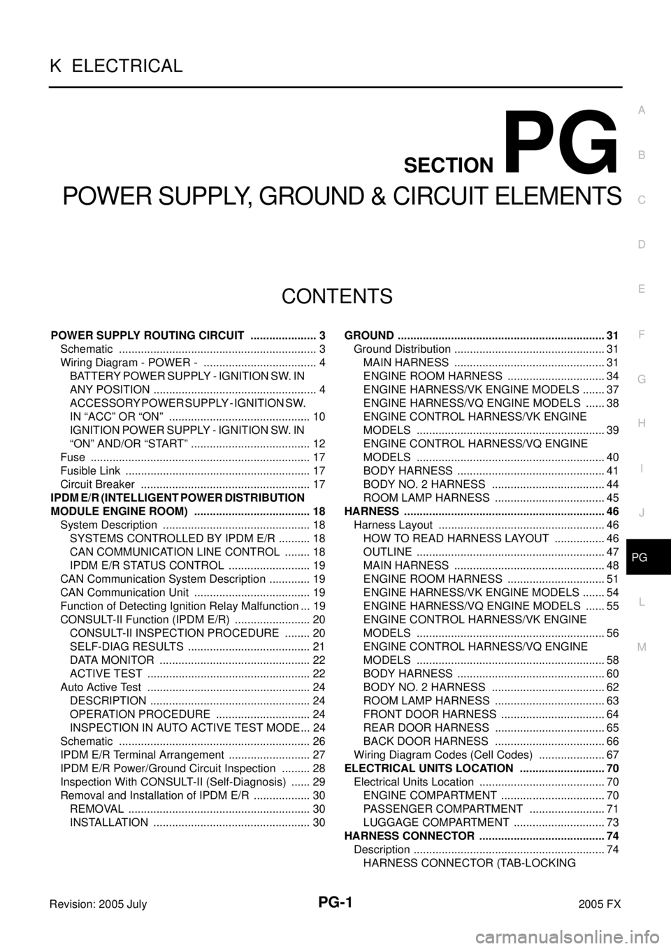
POWER SUPPLY, GROUND & CIRCUIT ELEMENTS
POWER SUPPLY ROUTING CIRCUIT ...................... 3
Schematic ........................................................... ..... 3
Wiring Diagram - POWER - ................................ ..... 4
BATTERY POWER SUPPLY - IGNITION SW. IN
ANY POSITION ................................................ ..... 4
ACCESSORY POWER SUPPLY - IGNITION SW.
IN “ACC” OR “ON” ........................................... ... 10
IGNITION POWER SUPPLY - IGNITION SW. IN
“ON” AND/OR “START” .................................... ... 12
Fuse .................................................................... ... 17
Fusible Link ......................................................... ... 17
Circuit Breaker .................................................... ... 17
IPDM E/R (INTELLIGENT POWER DISTRIBUTION
MODULE ENGINE ROOM) ................................... ... 18
System Description ............................................. ... 18
SYSTEMS CONTROLLED BY IPDM E/R ........ ... 18
CAN COMMUNICATION LINE CONTROL ...... ... 18
IPDM E/R STATUS CONTROL ........................ ... 19
CAN Communication System Description ........... ... 19
CAN Communication Unit ................................... ... 19
Function of Detecting Ignition Relay Malfunction ... 19
CONSULT-II Function (IPDM E/R) ...................... ... 20
CONSULT-II INSPECTION PROCEDURE ...... ... 20
SELF-DIAG RESULTS ..................................... ... 21
DATA MONITOR .............................................. ... 22
ACTIVE TEST .................................................. ... 22
Auto Active Test .................................................. ... 24
DESCRIPTION ................................................. ... 24
OPERATION PROCEDURE ............................ ... 24
INSPECTION IN AUTO ACTIVE TEST MODE ... 24
Schematic ........................................................... ... 26
IPDM E/R Terminal Arrangement ........................ ... 27
IPDM E/R Power/Ground Circuit Inspection ....... ... 28
Inspection With CONSULT-II (Self-Diagnosis) .... ... 29
Removal and Installation of IPDM E/R ................ ... 30
REMOVAL ........................................................ ... 30
INSTALLATION ................................................ ... 30 GROUND ................................................................
... 31
Ground Distribution .............................................. ... 31
MAIN HARNESS .............................................. ... 31
ENGINE ROOM HARNESS ............................. ... 34
ENGINE HARNESS/VK ENGINE MODELS ..... ... 37
ENGINE HARNESS/VQ ENGINE MODELS .... ... 38
ENGINE CONTROL HARNESS/VK ENGINE
MODELS .......................................................... ... 39
ENGINE CONTROL HARNESS/VQ ENGINE
MODELS .......................................................... ... 40
BODY HARNESS ............................................. ... 41
BODY NO. 2 HARNESS .................................. ... 44
ROOM LAMP HARNESS ................................. ... 45
HARNESS .............................................................. ... 46
Harness Layout ................................................... ... 46
HOW TO READ HARNESS LAYOUT .............. ... 46
OUTLINE .......................................................... ... 47
MAIN HARNESS .............................................. ... 48
ENGINE ROOM HARNESS ............................. ... 51
ENGINE HARNESS/VK ENGINE MODELS ..... ... 54
ENGINE HARNESS/VQ ENGINE MODELS .... ... 55
ENGINE CONTROL HARNESS/VK ENGINE
MODELS .......................................................... ... 56
ENGINE CONTROL HARNESS/VQ ENGINE
MODELS .......................................................... ... 58
BODY HARNESS ............................................. ... 60
BODY NO. 2 HARNESS .................................. ... 62
ROOM LAMP HARNESS ................................. ... 63
FRONT DOOR HARNESS ............................... ... 64
REAR DOOR HARNESS ................................. ... 65
BACK DOOR HARNESS ................................. ... 66
Wiring Diagram Codes (Cell Codes) ................... ... 67
ELECTRICAL UNITS LOCATION ......................... ... 70
Electrical Units Location ...................................... ... 70
ENGINE COMPARTMENT ............................... ... 70
PASSENGER COMPARTMENT ...................... ... 71
LUGGAGE COMPARTMENT ........................... ... 73
HARNESS CONNECTOR ...................................... ... 74
Description ........................................................... ... 74
HARNESS CONNECTOR (TAB-LOCKING
Page 4181 of 4731
PG-4
POWER SUPPLY ROUTING CIRCUIT
Revision: 2005 July 2005 FX
Wiring Diagram - POWER -AKS007VV
BATTERY POWER SUPPLY - IGNITION SW. IN ANY POSITION
TKWM0708E
Page 4244 of 4731

HARNESS PG-67
C
D E
F
G H
I
J
L
M A
B
PG
Revision: 2005 July 2005 FX
Wiring Diagram Codes (Cell Codes) AKS007X0
Use the chart below to find out what each wiring diagram code stands for.
Refer to the wiring diagram code in the alphabetical index to find the location (page number) of each wiring
diagram.
Code Section Wiring Diagram Name
A/C ATC Air Conditioner
APPS1 EC Accelerator Pedal Position Sensor
APPS2 EC Accelerator Pedal Position Sensor
APPS3 EC Accelerator Pedal Position Sensor
ASC/BS EC Automatic Speed Control Device (ASCD) Brake Switch
ASC/SW EC Automatic Speed Control Device (ASCD) Steering Switch
ASCBOF EC Automatic Speed Control Device (ASCD) Brake Switch
ASCIND EC Automatic Speed Control Device (ASCD) Indicator
AT/IND DI A/T Indicator Lamp
AUDIO AV Audio
AUT/DP SE Automatic Drive Positioner
AUTO/L LT Automatic Light System
AWD TF AWD Control System
B/CLOS BL Back Door Closure System
BACK/L LT Back-Up Lamp
BRK/SW EC Brake Switch
CAN AT CAN Communication Line
CAN EC CAN Communication Line
CAN LAN CAN System
CHARGE SC Charging System
CHIME DI Warning Chime
CIGAR WW Cigarette Lighter
CLOCK DI Clock
COMBSW LT Combination Switch
COMM AV Audio Visual Communication Line
COMPAS DI Compass
COOL/F EC Cooling Fan Control
D/LOCK BL Power Door Lock
DEF GW Rear Window Defogger
DTRL LT Headlamp - With Daytime Light System
ECM/PW EC ECM Power Supply for Back-Up
ECTS EC Engine Coolant Temperature Sensor
ETC1 EC Electric Throttle Control Function
ETC2 EC Electric Throttle Control Motor Relay
ETC3 EC Electric Throttle Control Motor
F/FOG LT Front Fog Lamp
F/PUMP EC Fuel Pump
FTS AT A/T Fluid Temperature Sensor Circuit
FTTS EC Fuel Tank Temperature Sensor
FUELB1 EC Fuel Injection System Function (Bank 1)
FUELB2 EC Fuel Injection System Function (Bank 2)