Page 3202 of 4731

FUEL TANK FL-11
C
D E
F
G H
I
J
K L
M A
FL
Revision: 2005 July 2005 FX
9. Disconnect fuel filler hose, vent hose and EVAP hoses at fuel
tank side.
10. Support the lower part of fuel tank with transmission jack. CAUTION:
Support the position that fuel tank mounting bands do not
engage.
11. Remove fuel tank mounting bands.
12. Supporting with hands, descend transmission jack carefully, and remove fuel tank. CAUTION:
�Make sure that all connection points have been disconnected.
�Confirm there is no interference with vehicle.
13. Remove fuel filler tube protector and fuel filler tube, if necessary.
INSTALLATION
Note the following, and install in the reverse order of removal.
�Surely clamp fuel hoses and insert hose to the length below.
�Be sure hose clamp is not placed on swelled area of fuel tube.
�Tighten fuel hose clamp so that the distance between its lugs becomes to the following.
�To connect quick connector, refer to FL-7, "Quick Connector" .
INSPECTION AFTER INSTALLATION
Use the following procedure to check for fuel leaks.
1. Turn ignition switch “ON” (with engine stopped), and check connections for leakage by applying fuel pres- sure to fuel piping.
2. Start engine and rev it up and make sure there are no fuel leaks at the fuel system tube and hose connec- tions.
�After removing/installing rear suspension assembly, make sure to adjust wheel alignment and then, adjust
neutral position of steering angle sensor. Refer to RSU-5, "
Wheel Alignment Inspection" and BRC-6,
"Adjustment of Steering Angle Sensor Neutral Position" .
PBIC1581E
PBIC0878E
Fuel filler hose : 35 mm (1.38 in)
The other hoses : 25 mm (0.98 in)
Fuel tank side : 8 - 12 mm (0.31 - 0.47 in)
Fuel filler tube side : 5.7 - 9.7 mm (0.224 - 0.382 in)
Page 3204 of 4731

FSU-1
FRONT SUSPENSION
E SUSPENSION
CONTENTS
C
D
F
G H
I
J
K L
M
SECTION FSU
A
B
FSU
Revision: 2005 July 2005 FX
FRONT SUSPENSION
PRECAUTIONS .......................................................... 2
Caution ................................................................ ..... 2
PREPARATION ...................................................... ..... 3
Special Service Tools (SST) ................................ ..... 3
Commercial Service Tools ................................... ..... 4
NOISE, VIBRATION AND HARSHNESS (NVH)
TROUBLESHOOTING ........................................... ..... 5
NVH Troubleshooting Chart ................................ ..... 5
FRONT SUSPENSION ASSEMBLY ...................... ..... 6
On-Vehicle Inspection and Service ..................... ..... 6
INSPECTION OF TRANSVERSE LINK BALL
JOINT END PLAY ............................................ ..... 6
STRUT INSPECTION ...................................... ..... 6
Wheel Alignment Inspection ................................ ..... 6
DESCRIPTION ................................................. ..... 6
PRELIMINARY CHECK ................................... ..... 6
INSPECTION OF CAMBER, CASTER AND
KINGPIN INCLINATION ANGLES ................... ..... 6
Components ........................................................ ..... 8
Removal and Installation ..................................... ..... 9
REMOVAL ........................................................ ..... 9
INSTALLATION ................................................ ... 10
COIL SPRING AND STRUT .................................. ....11
Removal and Installation ..................................... .... 11
REMOVAL ........................................................ .... 11 INSTALLATION ................................................
... 11
Disassembly and Assembly ................................. ... 12
DISASSEMBLY ................................................ ... 12
INSPECTION AFTER DISASSEMBLY ............. ... 12
ASSEMBLY ...................................................... ... 13
TRANSVERSE LINK .............................................. ... 14
Removal and Installation ..................................... ... 14
REMOVAL ........................................................ ... 14
INSPECTION AFTER REMOVAL .................... ... 14
INSTALLATION ................................................ ... 15
STABILIZER BAR .................................................. ... 16
Removal and Installation ..................................... ... 16
REMOVAL ........................................................ ... 16
INSPECTION AFTER REMOVAL .................... ... 16
INSTALLATION ................................................ ... 16
FRONT SUSPENSION MEMBER .......................... ... 17
Removal and Installation ..................................... ... 17
REMOVAL ........................................................ ... 17
INSPECTION AFTER REMOVAL .................... ... 17
INSTALLATION ................................................ ... 17
SERVICE DATA ..................................................... ... 18
Wheel Alignment (Unladen) ................................. ... 18
Ball Joint .............................................................. ... 18
Wheelarch Height (Unladen*) .............................. ... 18
Page 3205 of 4731
FSU-2
PRECAUTIONS
Revision: 2005 July 2005 FX
PRECAUTIONSPFP:00001
CautionAES000MZ
�When installing rubber bushings, final tightening must be carried out under unladen conditions with tires
on ground. Oil will shorten the life of rubber bushings. Be sure to wipe off any spilled oil.
�Unladen conditions mean that fuel, engine coolant and lubricant are full. Spare tire, jack, hand tools and
mats are in designated positions.
�After servicing suspension parts, be sure to check wheel alignment.
�Caulking nuts are not reusable. Always use new ones when installing. Since new caulking nuts are pre-
oiled, tighten as they are.
�Avoid burden to front cross bar.
Page 3207 of 4731
FSU-4
PREPARATION
Revision: 2005 July 2005 FX
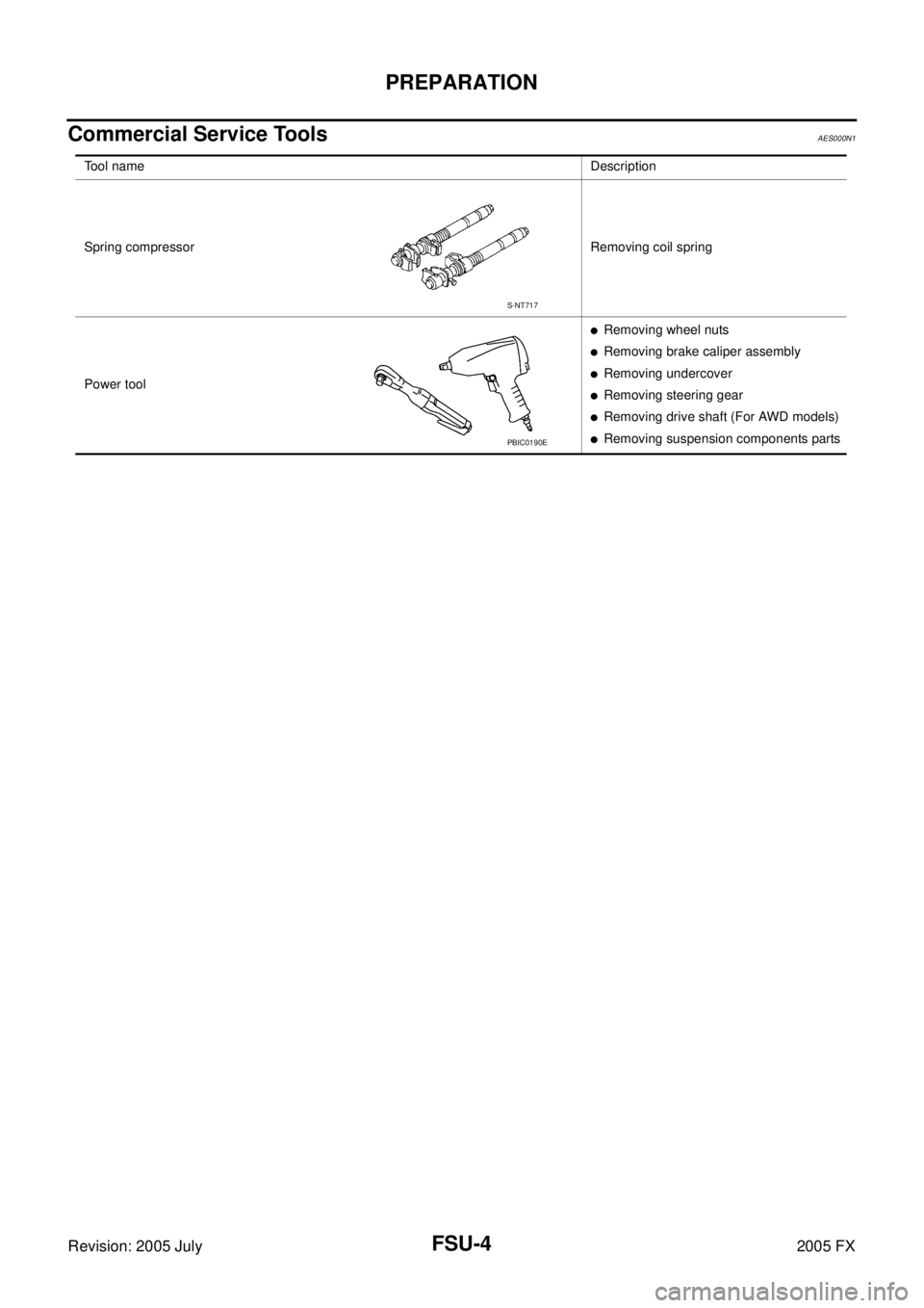
Commercial Service ToolsAES000N1
Tool nameDescription
Spring compressor Removing coil spring
Power tool
�Removing wheel nuts
�Removing brake caliper assembly
�Removing undercover
�Removing steering gear
�Removing drive shaft (For AWD models)
�Removing suspension components parts
S-NT717
PBIC0190E
Page 3208 of 4731
 TROUBLESHOOTING FSU-5
C
D
F
G H
I
J
K L
M A
B
FSU
Revision: 2005 July 2005 FX
NOISE, VIBRATION AND HARSHNESS (NVH) TROUBLESHOOTINGPFP:00003
NVH Troubl")
NOISE, VIBRATION AND HARSHNESS (NVH) TROUBLESHOOTING FSU-5
C
D
F
G H
I
J
K L
M A
B
FSU
Revision: 2005 July 2005 FX
NOISE, VIBRATION AND HARSHNESS (NVH) TROUBLESHOOTINGPFP:00003
NVH Troubleshooting ChartAES000N2
Use chart below to help you find the cause of the symptom. If necessary, repair or replace these parts.
×: Applicable Reference page
FSU-8FSU-12
—
—
—
FSU-8FSU-6FSU-16
NVH in PR section
NVH in RFD section
NVH in RAX and RSU section
NVH in WT section
NVH in WT section
NVH in RAX section NVH in BR section NVH in PS section
Possible cause and SUSPECTED PARTS
Improper installation, looseness
Strut deformation, damage or deflection
Bushing or mounting deterioration
Parts interference
Spring fatigue
Suspension looseness
Incorrect wheel alignment
Stabilizer bar fatigue
PROPELLER SHAFT (For AWD models)
DIFFERENTIAL (For AWD models)
REAR AXLE AND REAR SUSPENSION
TIRES
ROAD WHEEL
DRIVE SHAFT (For AWD models)
BRAKES
STEERING
Symptom FRONT SUSPENSION Noise
××××× × ××× ×××××
Shake ×××× × × × ×××××
Vibration ××××× × ×× × ×
Shimmy ×××× × ××× ××
Judder ××× ××× ××
Poor quality ride or han-
dling ××××× ×× ×××
Page 3209 of 4731
 of eac")
FSU-6
FRONT SUSPENSION ASSEMBLY
Revision: 2005 July 2005 FX
FRONT SUSPENSION ASSEMBLYPFP:54010
On-Vehicle Inspection and ServiceAES000N3
Make sure the mounting conditions (looseness, back lash) of each component and component statues (wear,
damage) are normal.
INSPECTION OF TRANSVERSE LINK BALL JOINT END PLAY
1. Set front wheels in a straight-ahead position. Do not depress brake pedal.
2. Measure axial end play by installing and moving up/down between transverse link and steering knuckle with an iron pry bar or something similar.
CAUTION:
Be careful not to damage ball joint boot.
STRUT INSPECTION
Check strut for oil leakage, damage and replace if necessary. Refer to FSU-11, "COIL SPRING AND STRUT" .
Wheel Alignment InspectionAES000N4
DESCRIPTION
Measure wheel alignment under unladen conditions.
NOTE:
Unladen conditions mean that fuel, engine coolant, and lubricant are full. Spare tire, jack, hand tools and mats
are designated positions.
PRELIMINARY CHECK
1. Check tires for improper air pressure and wear.
2. Check road wheels for runout.
3. Check wheel bearing axial end play.
4. Check transverse link ball joint axial end play.
5. Check strut operation.
6. Check each mounting part of axle and suspension for looseness and deformation.
7. Check each link, rod and member for cracks, deformation and other damage.
8. Check vehicle posture.
INSPECTION OF CAMBER, CASTER AND KINGPIN INCLINATION ANGLES
�Camber, caster, kingpin inclination angles cannot be adjusted.
�Before inspection, mount front wheels onto turning radius gauge. Mount rear wheels onto a stand that has
same height so vehicle will remain horizontal.
Using a CCK Gauge
Install CCK gauge attachment (SST: KV991040S0) as following procedure in wheel, then measure wheel
alignment.
1. Remove wheel nuts (3), and install a guide bolt to hub bolt.
2. Screw adapter into plate body until it contacts body tightly.
3. Screw center plate into plate.
4. Insert plate on guide bolt. Put spring in, and then evenly screw both guide bolt nut. When fastening guide bolt nut, do not com-
pletely compress spring. Axial end play : 0 mm (0 in)
SEIA0240E
Page 3210 of 4731

FRONT SUSPENSION ASSEMBLY FSU-7
C
D
F
G H
I
J
K L
M A
B
FSU
Revision: 2005 July 2005 FX
5. Place the dent of alignment gauge onto the projection of center
plate and tightly contact them to measure.
CAUTION:
�If camber, caster, or kingpin inclination angle is outside
the standard, check front suspension parts for wear and
damage, and replace suspect parts if necessary.
�King pin inclination angle is reference value, no inspec-
tion is required.
Toe-In Inspection
Measure toe-in using the following procedure.
WARNING:
�Always perform the following procedure on a flat surface.
�Make sure that no person is in front of vehicle before push-
ing it.
1. Bounce front of vehicle up and down to stabilize the posture.
2. Push vehicle straight ahead about 5 m (16 ft).
3. Put a mark on base line of the tread (rear side) of both tires at the same height of hub center. These are measuring points.
4. Measure distance “A” (rear side).
5. Push vehicle slowly ahead to rotate wheels 180 degrees (1/2 turn).
If wheels have rotated more than 180 degrees (1/2 turn), try the
above procedure again from the beginning. Never push vehicle
backward.
6. Measure distance “B” (front side). Camber, caster, kingpin inclination angles:
Refer to FSU-18, "
SERVICE DATA"FSU-18, "SER-
VICE DATA" .
SEIA0241E
SEIA0362E
Total toe-in : Refer to FSU-18, "SERVICE DATA" .
SEIA0363E
Page 3211 of 4731
FSU-8
FRONT SUSPENSION ASSEMBLY
Revision: 2005 July 2005 FX
ComponentsAES000N5
SEIA0349E