Page 1245 of 4731
CO-40
[VK45DE]
ENGINE COOLANT
Revision: 2005 July 2005 FX
5. Rev engine two or three times under no-load.
6. Stop engine and wait until it cools down.
7. Drain water from the system. Refer to CO-37, "
DRAINING ENGINE COOLANT" .
8. Repeat steps 1 through 7 until clear water begins to drain from radiator.
Page 1246 of 4731
![INFINITI FX35 2005 Service Manual RADIATOR CO-41
[VK45DE]
C
D E
F
G H
I
J
K L
M A
CO
Revision: 2005 July 2005 FX
RADIATORPFP:21400
Removal and InstallationABS006JS
WARNING:
Do not remove radiator cap when engine is hot.](/manual-img/42/57020/w960_57020-1245.png "INFINITI FX35 2005 Service Manual RADIATOR CO-41
[VK45DE]
C
D E
F
G H
I
J
K L
M A
CO
Revision: 2005 July 2005 FX
RADIATORPFP:21400
Removal and InstallationABS006JS
WARNING:
Do not remove radiator cap when engine is hot.")
RADIATOR CO-41
[VK45DE]
C
D E
F
G H
I
J
K L
M A
CO
Revision: 2005 July 2005 FX
RADIATORPFP:21400
Removal and InstallationABS006JS
WARNING:
Do not remove radiator cap when engine is hot. Serious burns could occur from high-pressure engine
coolant escaping from radiator. Wrap a thick cloth around radiator cap. Slowly turn it a quarter of a
turn to release built-up pressure. Carefully remove radiator cap by turning it all the way.
REMOVAL
1. Remove engine cover with power tool. Refer to EM-172, "ENGINE ROOM COVER" .
2. Remove engine front undercover with power tool.
3. Drain engine coolant from radiator. Refer to CO-37, "
Changing Engine Coolant" .
CAUTION:
Perform this step when engine is cold.
4. Remove air duct (inlet), air cleaner case and mass air flow sensor assembly. Refer to EM-176, "
AIR
CLEANER AND AIR DUCT" .
5. Remove radiator hoses (upper and lower). CAUTION:
Do not spill engine coolant on drive belts.
6. Disconnect A/T fluid cooler hoses.
1. Radiator 2. Upper mount bracket 3. Mounting rubber
4. Radiator hose (lower) 5. Radiator drain plug 6. O-ring
7. A/T fluid cooler hose 8. Radiator hose (upper) 9. Reservoir tank hose
10. Reservoir tank cap 11. Reservoir tank 12. Radiator shroud (lower)
13. Radiator shroud
PBIC1531E
Page 1248 of 4731
![INFINITI FX35 2005 Service Manual RADIATOR CO-43
[VK45DE]
C
D E
F
G H
I
J
K L
M A
CO
Revision: 2005 July 2005 FX
11. Lift up and remove radiator.
CAUTION:
Do not damage or scratch A/C condenser and radiator core
when re](/manual-img/42/57020/w960_57020-1247.png "INFINITI FX35 2005 Service Manual RADIATOR CO-43
[VK45DE]
C
D E
F
G H
I
J
K L
M A
CO
Revision: 2005 July 2005 FX
11. Lift up and remove radiator.
CAUTION:
Do not damage or scratch A/C condenser and radiator core
when re")
RADIATOR CO-43
[VK45DE]
C
D E
F
G H
I
J
K L
M A
CO
Revision: 2005 July 2005 FX
11. Lift up and remove radiator.
CAUTION:
Do not damage or scratch A/C condenser and radiator core
when removing.
INSTALLATION
Install in the reverse order of removal.
INSPECTION AFTER INSTALLATION
�Check for leaks of engine coolant using radiator cap tester adapter [SST: EG17650301 (J33984-A)] and
radiator cap tester (commercial service tool). Refer to CO-37, "
LEAK CHECK" .
�Start and warm up engine. Visually Check if there is no leaks of engine coolant and A/T fluid.
Checking Radiator CapABS008FY
�Check valve seat of radiator cap.
–Check if valve seat is swollen to the extent that the edge of the
plunger cannot be seen when watching it vertically from the top.
–Check if valve seat has no soil and damage.
�Pull negative-pressure valve to open it, and make sure that it
close completely when released.
–Make sure that there is no dirt or damage on the valve seat of
radiator cap negative-pressure valve.
–Make sure that there are no unusualness in the opening and
closing conditions of negative-pressure valve.
�Check radiator cap relief pressure.
–When connecting radiator cap to the radiator cap tester adapter
(SST) and the radiator cap tester (Commercial service tool),
apply engine coolant to the cap seal surface.
�Replace radiator cap if there is an unusualness.
PBIC1536E
PBIC2816E
SMA967B
Standard : 78 - 98 kPa (0.8 - 1.0 kg/cm2 , 11 - 14 psi)
Limit : 59 kPa (0.6 kg/cm
2 , 9 psi)
SLC755A
Page 1256 of 4731
![INFINITI FX35 2005 Service Manual WATER PUMP CO-51
[VK45DE]
C
D E
F
G H
I
J
K L
M A
CO
Revision: 2005 July 2005 FX
WAT E R P U MPPFP:21020
Removal and InstallationABS006JO
CAUTION:
�When removing water pump, be careful n](/manual-img/42/57020/w960_57020-1255.png "INFINITI FX35 2005 Service Manual WATER PUMP CO-51
[VK45DE]
C
D E
F
G H
I
J
K L
M A
CO
Revision: 2005 July 2005 FX
WAT E R P U MPPFP:21020
Removal and InstallationABS006JO
CAUTION:
�When removing water pump, be careful n")
WATER PUMP CO-51
[VK45DE]
C
D E
F
G H
I
J
K L
M A
CO
Revision: 2005 July 2005 FX
WAT E R P U MPPFP:21020
Removal and InstallationABS006JO
CAUTION:
�When removing water pump, be careful not to get engine coolant on drive belts.
�Water pump can not be disassembled and should be replaced as a unit.
�After installing water pump, connect hose and clamp securely, then check for leaks using radiator
cap tester (commercial service tool) and radiator cap tester adapter [SST: EG17650301 (J33984-
A)].
REMOVAL
1. Drain engine coolant from drain plugs on radiator and both side of cylinder block. Refer to CO-37, "Chang-
ing Engine Coolant" and EM-246, "DISASSEMBLY" .
CAUTION:
�Perform this step when engine is cold.
�Do not spill engine coolant on drive belts.
2. Remove following parts:
�Engine front undercover
�Air duct (inlet); Refer to EM-176, "AIR CLEANER AND AIR DUCT" .
�Alternator, water pump and A/C compressor belt; Refer to EM-173, "DRIVE BELTS" .
3. Remove fan coupling with cooling fan, and then water pump pulley.
4. Remove water pump.
�Engine coolant will leak from cylinder block, so have a receptacle ready under vehicle.
CAUTION:
�Handle the water pump vane so that it does not contact any other parts.
�Do not disassemble water pump.
1. Water pump pulley 2. Water pump 3. Gasket
PBIC1538E
Page 1257 of 4731
CO-52
[VK45DE]
WATER PUMP
Revision: 2005 July 2005 FX
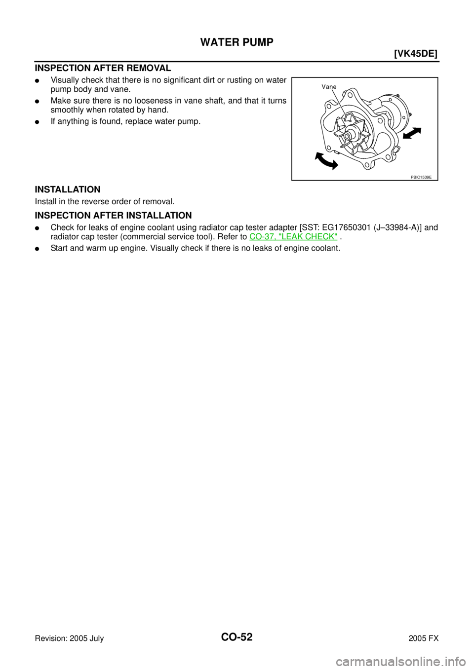
INSPECTION AFTER REMOVAL
�Visually check that there is no significant dirt or rusting on water
pump body and vane.
�Make sure there is no looseness in vane shaft, and that it turns
smoothly when rotated by hand.
�If anything is found, replace water pump.
INSTALLATION
Install in the reverse order of removal.
INSPECTION AFTER INSTALLATION
�Check for leaks of engine coolant using radiator cap tester adapter [SST: EG17650301 (J–33984-A)] and
radiator cap tester (commercial service tool). Refer to CO-37, "
LEAK CHECK" .
�Start and warm up engine. Visually check if there is no leaks of engine coolant.
PBIC1539E
Page 1258 of 4731
![INFINITI FX35 2005 Service Manual THERMOSTAT AND WATER CONTROL VALVE CO-53
[VK45DE]
C
D E
F
G H
I
J
K L
M A
CO
Revision: 2005 July 2005 FX
THERMOSTAT AND WATER CONTROL VALVEPFP:21200
Removal and InstallationABS006JP
REMOV](/manual-img/42/57020/w960_57020-1257.png "INFINITI FX35 2005 Service Manual THERMOSTAT AND WATER CONTROL VALVE CO-53
[VK45DE]
C
D E
F
G H
I
J
K L
M A
CO
Revision: 2005 July 2005 FX
THERMOSTAT AND WATER CONTROL VALVEPFP:21200
Removal and InstallationABS006JP
REMOV")
THERMOSTAT AND WATER CONTROL VALVE CO-53
[VK45DE]
C
D E
F
G H
I
J
K L
M A
CO
Revision: 2005 July 2005 FX
THERMOSTAT AND WATER CONTROL VALVEPFP:21200
Removal and InstallationABS006JP
REMOVAL
1. Drain engine coolant from drain plugs on radiator and both side of cylinder block. Refer to CO-37, "Chang-
ing Engine Coolant" and EM-246, "DISASSEMBLY" .
CAUTION:
�Perform this step when engine is cold.
�Do not spill engine coolant on drive belts.
2. Remove engine cover with power tool. Refer to EM-172, "
ENGINE ROOM COVER" .
3. Remove air duct (inlet). Refer to EM-176, "
AIR CLEANER AND AIR DUCT" .
4. Disconnect water suction hose from water inlet.
5. Remove water inlet and thermostat. CAUTION:
Do not disassemble thermostat.
6. Remove intake manifolds (upper and lower). Refer to EM-178, "
INTAKE MANIFOLD" .
1. Water connector 2. O-ring 3. Rubber ring
4. Heater hose 5. Water control valve 6. Water outlet
7. Gasket 8. O-ring 9. Water outlet pipe
10. Thermostat housing 11. Radiator cap 12. Radiator hose (upper)
13. Thermostat 14. Rubber ring 15. Water inlet
16. Water suction hose 17. Water suction pipe 18. Radiator hose (lower)
19. Gasket 20. O-ring 21. Heater pipe
22. Heater hose 23. Water hose 24. Water hose
PBIC1561E
Page 1259 of 4731
![INFINITI FX35 2005 Service Manual CO-54
[VK45DE]
THERMOSTAT AND WATER CONTROL VALVE
Revision: 2005 July 2005 FX
7. Disconnect radiator hose (upper) and water hoses from thermostat housing.
8. Disconnect heater hoses from water outlet](/manual-img/42/57020/w960_57020-1258.png "INFINITI FX35 2005 Service Manual CO-54
[VK45DE]
THERMOSTAT AND WATER CONTROL VALVE
Revision: 2005 July 2005 FX
7. Disconnect radiator hose (upper) and water hoses from thermostat housing.
8. Disconnect heater hoses from water outlet")
CO-54
[VK45DE]
THERMOSTAT AND WATER CONTROL VALVE
Revision: 2005 July 2005 FX
7. Disconnect radiator hose (upper) and water hoses from thermostat housing.
8. Disconnect heater hoses from water outlet and heater pipe.
9. Remove thermostat housing, water outlet pipe, water connector, water control valve, water outlet and heater pipe.
CAUTION:
Do not disassemble water control valve.
INSPECTION AFTER REMOVAL
�Make sure that valves both in thermostat and water control valve are completely closing at normal tempar-
ature.
�Place a thread so that it is caught in the valves of the thermostat
and water control valve. Immerse fully in a container filled with
water. Heat while stirring. (The example in the figure shows ther-
mostat.)
�The valve opening temperature is the temperature at which the
valve opens and falls from the thread.
�Continue heating. Check the maximum valve lift.
NOTE:
The maximum valve lift standard temperature for water control
valve is the reference value.
� After checking the maximum valve lift, lower the water tempera-
ture and check the valve closing temperature.
Standard values:
�If the malfunctioning condition, when closing valve at normal temperature, or measured values are out of
the standard, replace thermostat and/or water control valve.
INSTALLATION
Note the following, and install in the reverse order of removal.
CAUTION:
Be careful not to spill engine coolant over engine room. Use rag to absorb engine coolant.
Thermostat and Water Control Valve
�Install thermostat and water control valve with the whole circum-
ference of each flange part fit securely inside rubber ring. (The
example in the figure shows thermostat.)
SLC252B
Thermostat Water control valve
Valve opening temperature 80 - 84 °C (176 - 183 °F) 93.5 - 96.5 °C (200 - 206 °F)
Maximum valve lift More than 10 mm/ 95
°C
(0.39 in/ 203 °F) More than 8 mm/ 108
°C
(0.315 in/ 226 °F)
Valve closing temperature 77 °C (171 °F) 90 °C (194 °F)
PBIC0157E
Page 1260 of 4731
THERMOSTAT AND WATER CONTROL VALVE CO-55
[VK45DE]
C
D E
F
G H
I
J
K L
M A
CO
Revision: 2005 July 2005 FX
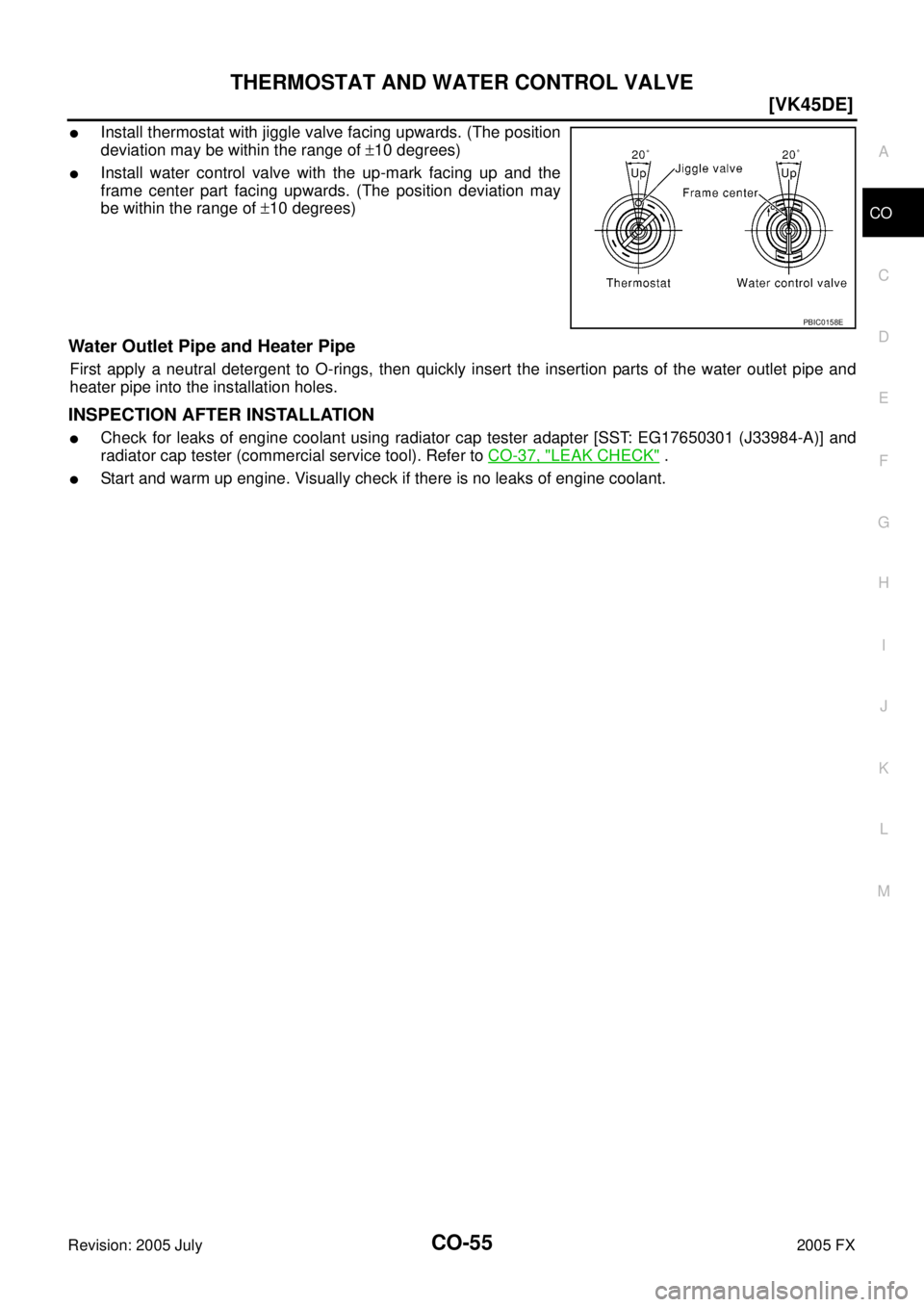
�Install thermostat with jiggle valve facing upwards. (The position
deviation may be within the range of ±10 degrees)
�Install water control valve with the up-mark facing up and the
frame center part facing upwards. (The position deviation may
be within the range of ±10 degrees)
Water Outlet Pipe and Heater Pipe
First apply a neutral detergent to O-rings, then quickly insert the insertion parts of the water outlet pipe and
heater pipe into the installation holes.
INSPECTION AFTER INSTALLATION
�Check for leaks of engine coolant using radiator cap tester adapter [SST: EG17650301 (J33984-A)] and
radiator cap tester (commercial service tool). Refer to CO-37, "
LEAK CHECK" .
�Start and warm up engine. Visually check if there is no leaks of engine coolant.
PBIC0158E
![INFINITI FX35 2005 Service Manual CO-40
[VK45DE]
ENGINE COOLANT
Revision: 2005 July 2005 FX
5. Rev engine two or three times under no-load.
6. Stop engine and wait until it cools down.
7. Drain water from the system. Refer to CO-37](/manual-img/42/57020/w960_57020-1244.png "INFINITI FX35 2005 Service Manual CO-40
[VK45DE]
ENGINE COOLANT
Revision: 2005 July 2005 FX
5. Rev engine two or three times under no-load.
6. Stop engine and wait until it cools down.
7. Drain water from the system. Refer to CO-37")