Page 1327 of 4731
DI-66
WARNING CHIME
Revision: 2005 July 2005 FX
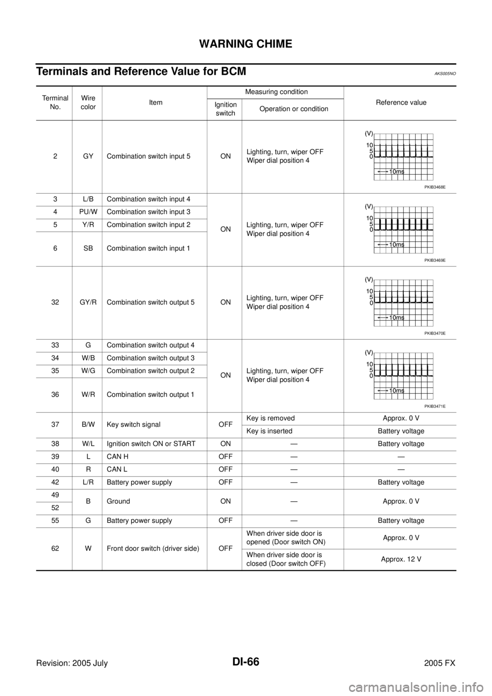
Terminals and Reference Value for BCMAKS005NO
Te r m i n a l
No. Wire
color Item Measuring condition
Reference value
Ignition
switch Operation or condition
2 GY Combination switch input 5 ON Lighting, turn, wiper OFF
Wiper dial position 4
3 L/B Combination switch input 4 ON Lighting, turn, wiper OFF
Wiper dial position 4
4 PU/W Combination switch input 3
5 Y/R Combination switch input 2
6 SB Combination switch input 1
32 GY/R Combination switch output 5 ON Lighting, turn, wiper OFF
Wiper dial position 4
33 G Combination switch output 4 ON Lighting, turn, wiper OFF
Wiper dial position 4
34 W/B Combination switch output 3
35 W/G Combination switch output 2
36 W/R Combination switch output 1
37 B/W Key switch signal OFF Key is removed Approx. 0 V
Key is inserted Battery voltage
38 W/L Ignition switch ON or START ON — Battery voltage
39 L CAN H OFF — —
40 R CAN L OFF — —
42 L/R Battery power supply OFF — Battery voltage
49 B Ground ON — Approx. 0 V
52
55 G Battery power supply OFF — Battery voltage
62 W Front door switch (driver side) OFF When driver side door is
opened (Door switch ON) Approx. 0 V
When driver side door is
closed (Door switch OFF) Approx. 12 V
PKIB3468E
PKIB3469E
PKIB3470E
PKIB3471E
Page 1328 of 4731
WARNING CHIME DI-67
C
D E
F
G H
I
J
L
M A
B
DI
Revision: 2005 July 2005 FX
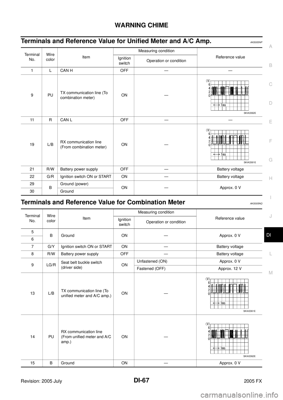
Terminals and Reference Value for Unified Meter and A/C Amp. AKS005NP
Terminals and Reference Value for Combination MeterAKS005NQ
Terminal
No. Wire
color Item Measuring condition
Reference value
Ignition
switch Operation or condition
1 L CAN H OFF — —
9PU TX communication line (To
combination meter) ON —
11 R C A N L O F F — —
19 L/B RX communication line
(From combination meter) ON —
21 R/W Battery power supply OFF — Battery voltage
22 G/R Ignition switch ON or START ON — Battery voltage
29 B Ground (power)
ON — Approx. 0 V
30 Ground
SKIA3362E
SKIA3361E
Terminal
No. Wire
color Item Measuring condition
Reference value
Ignition
switch Operation or condition
5 B Ground ON — Approx. 0 V
6
7 G/Y Ignition switch ON or START ON — Battery voltage
8 R/W Battery power supply OFF — Battery voltage
9 LG/R Seat belt buckle switch
(driver side) ON Unfastened (ON) Approx. 0 V
Fastened (OFF) Approx. 12 V
13 L/B TX communication line (To
unified meter and A/C amp.) ON —
14 PU RX communication line
(From unified meter and A/C
amp.) ON —
15 B Ground ON — Approx. 0 V
SKIA3361E
SKIA3362E
Page 1329 of 4731
DI-68
WARNING CHIME
Revision: 2005 July 2005 FX
Trouble DiagnosisAKS005NR
HOW TO PERFORM TROUBLE DIAGNOSIS
1. Confirm the malfunction symptom or customer complaint.
2. Understand operation description and function description. Refer to DI-58, "
System Description" .
3. Perform the Preliminary Check. Refer to DI-68, "
PRELIMINARY CHECK" .
4. Select “METER A/C AMP” on CONSULT-II, and perform self-diagnosis of unified meter and A/C amp. Refer to DI-31, "
CONSULT-II Function (METER A/C AMP)" . When no malfunction detected, go to next
step 5. When malfunction detected, go to DI-17, "
Symptom Chart 2" in “COMBINATION METER”.
5. Check symptom and repair or replace the cause of malfunction.
6. Does the warning chime operate normally? If so, GO TO 7. If not, GO TO 5.
7. INSPECTION END
PRELIMINARY CHECK
Inspection for Power Supply and Ground Circuit
1. CHECK FUSE AND FUSIBLE LINK
Check BCM fuses and fusible link for blown-out.
OK or NG
OK >> GO TO 2.
NG >> If fuse or fusible link is blown, be sure to eliminate cause of malfunction before installing new fuse or fusible link. Refer to PG-3, "
POWER SUPPLY ROUTING CIRCUIT" .
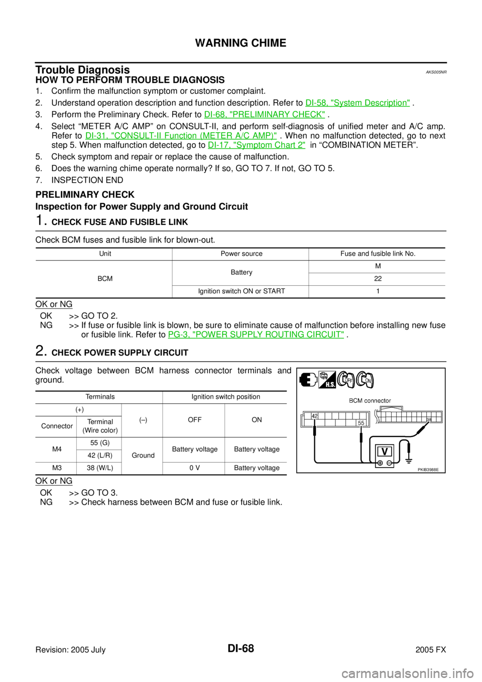
2. CHECK POWER SUPPLY CIRCUIT
Check voltage between BCM harness connector terminals and
ground.
OK or NG
OK >> GO TO 3.
NG >> Check harness between BCM and fuse or fusible link.
Unit Power source Fuse and fusible link No.
BCM Battery
M
22
Ignition switch ON or START 1
Terminals Ignition switch position
(+) (–) OFF ON
Connector Terminal
(Wire color)
M4 55 (G)
Ground Battery voltage Battery voltage
42 (L/R)
M3 38 (W/L) 0 V Battery voltage
PKIB3988E
Page 1330 of 4731
WARNING CHIME DI-69
C
D E
F
G H
I
J
L
M A
B
DI
Revision: 2005 July 2005 FX
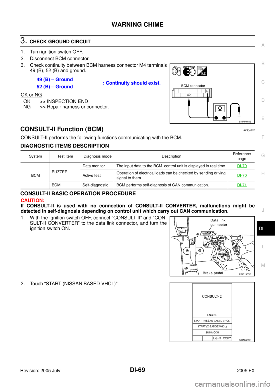
3. CHECK GROUND CIRCUIT
1. Turn ignition switch OFF.
2. Disconnect BCM connector.
3. Check continuity between BCM harness connector M4 terminals 49 (B), 52 (B) and ground.
OK or NG
OK >> INSPECTION END
NG >> Repair harness or connector.
CONSULT-II Function (BCM)AKS005NT
CONSULT-II performs the following functions communicating with the BCM.
DIAGNOSTIC ITEMS DESCRIPTION
CONSULT-II BASIC OPERATION PROCEDURE
CAUTION:
If CONSULT-II is used with no connection of CONSULT-II CONVERTER, malfunctions might be
detected in self-diagnosis depending on control unit which carry out CAN communication.
1. With the ignition switch OFF, connect “CONSULT-II” and “CON- SULT-II CONVERTER” to the data link connector, and turn the
ignition switch ON.
2. Touch “START (NISSAN BASED VHCL)”. 49 (B) – Ground
: Continuity should exist.
52 (B) – Ground
SKIA5041E
System Test item Diagnosis mode Description Reference
page
BCM BUZZER Data monitor The input data to the BCM control unit is displayed in real time.
DI-70
Active test Operation of electrical loads can be checked by sending driving
signal to them. DI-70
BCM Self-diagnostic BCM performs self-diagnosis of CAN communication.
DI-71
PBIB1503E
SAIA0450E
Page 1331 of 4731

DI-70
WARNING CHIME
Revision: 2005 July 2005 FX
3. Touch “BCM” on “SELECT SYSTEM” screen. If “BCM” is not
indicated, go to GI-39, "
CONSULT-II Data Link Connector (DLC)
Circuit" .
4. Touch “BUZZER” or “BCM”.
5. Select “DATA MONITOR”, “ACTIVE TEST” or “SELF-DIAG RESULTS”.
DATA MONITOR
Operation Procedure
1. Touch “BUZZER” on “SELECT TEST ITEM” screen.
2. Touch “DATA MONITOR” on “SELECT DIAG MODE” screen.
3. Touch “ALL SIGNALS” or “SELECTION FROM MENU” on “DATA MONITOR” screen.
4. If “SELECTION FROM MENU” is selected, touch the desired monitor item. If “ALL SIGNALS” is selected, all items required to control are monitored.
5. Touch “START”.
6. During monitoring, touching “RECORD” can start recording the monitored item status.
Display Item List
ACTIVE TEST
Operation Procedure
1. Touch “BUZZER” on “SELECT TEST ITEM” screen.
2. Touch “ACTIVE TEST” on “SELECT DIAG MODE” screen.
3. Touch the item to be tested, and check the operation.
4. During the operation check, touching “OFF” deactivates the operation.
PKIB1957E
PKIB1958E
ALL SIGNALS Monitors main items.
SELECTION FROM MENU Selects and monitors items.
Monitored item Description
IGN ON SW Indicates [ON/OFF] condition of ignition switch.
KEY ON SW Indicates [ON/OFF] condition of key switch.
DOOR SW-DR Indicates [ON/OFF] condition of front door switch (driver side).
LIGHT SW 1ST Indicates [ON/OFF] condition of lighting switch.
BUCKLE SW Indicates [ON/OFF] condition of seat belt switch (driver side).
Page 1333 of 4731
DI-72
WARNING CHIME
Revision: 2005 July 2005 FX
Key Warning Chime and Light Warning Chime Does Not Operate (Seat Belt
Warning Chime Does Operate)
AKS005NV
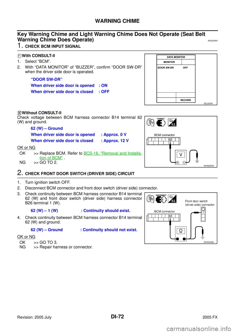
1. CHECK BCM INPUT SIGNAL
With CONSULT-ll
1. Select “BCM”.
2. With “DATA MONITOR” of “BUZZER”, confirm “DOOR SW-DR” when the driver side door is operated.
Without CONSULT-ll
Check voltage between BCM harness connector B14 terminal 62
(W) and ground.
OK or NG
OK >> Replace BCM. Refer to BCS-16, "Removal and Installa-
tion of BCM" .
NG >> GO TO 2.
2. CHECK FRONT DOOR SWITCH (DRIVER SIDE) CIRCUIT
1. Turn ignition switch OFF.
2. Disconnect BCM connector and front door switch (driver side) connector.
3. Check continuity between BCM harness connector B14 terminal 62 (W) and front door switch (driver side) harness connector
B26 terminal 1 (W).
4. Check continuity between BCM harness connector B14 terminal 62 (W) and ground.
OK or NG
OK >> GO TO 3.
NG >> Repair harness or connector. “DOOR SW-DR”
When driver side door is opened : ON
When driver side door is closed : OFF
SEL502W
62 (W) – Ground
When driver side door is opened : Approx. 0 V
When driver side door is closed : Approx. 12 V
SKIA8220E
62 (W) – 1 (W) : Continuity should exist.
62 (W) – Ground : Continuity should not exist.
SKIA5046E
Page 1335 of 4731
DI-74
WARNING CHIME
Revision: 2005 July 2005 FX
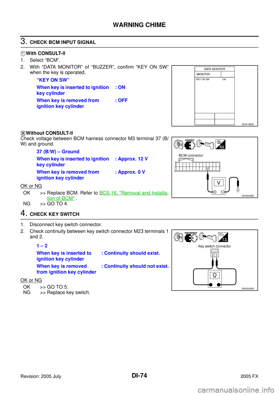
3. CHECK BCM INPUT SIGNAL
With CONSULT-ll
1. Select “BCM”.
2. With “DATA MONITOR” of “BUZZER”, confirm “KEY ON SW” when the key is operated.
Without CONSULT-ll
Check voltage between BCM harness connector M3 terminal 37 (B/
W) and ground.
OK or NG
OK >> Replace BCM. Refer to BCS-16, "Removal and Installa-
tion of BCM" .
NG >> GO TO 4.
4. CHECK KEY SWITCH
1. Disconnect key switch connector.
2. Check continuity between key switch connector M23 terminals 1 and 2.
OK or NG
OK >> GO TO 5.
NG >> Replace key switch. “KEY ON SW”
When key is inserted to ignition
key cylinder : ON
When key is removed from
ignition key cylinder : OFF
SKIA1960E
37 (B/W) – Ground
When key is inserted to ignition
key cylinder : Approx. 12 V
When key is removed from
ignition key cylinder : Approx. 0 V
SKIA5048E
1 – 2
When key is inserted to
ignition key cylinder : Continuity should exist.
When key is removed
from ignition key cylinder : Continuity should not exist.
SKIA5049E
Page 1336 of 4731
WARNING CHIME DI-75
C
D E
F
G H
I
J
L
M A
B
DI
Revision: 2005 July 2005 FX
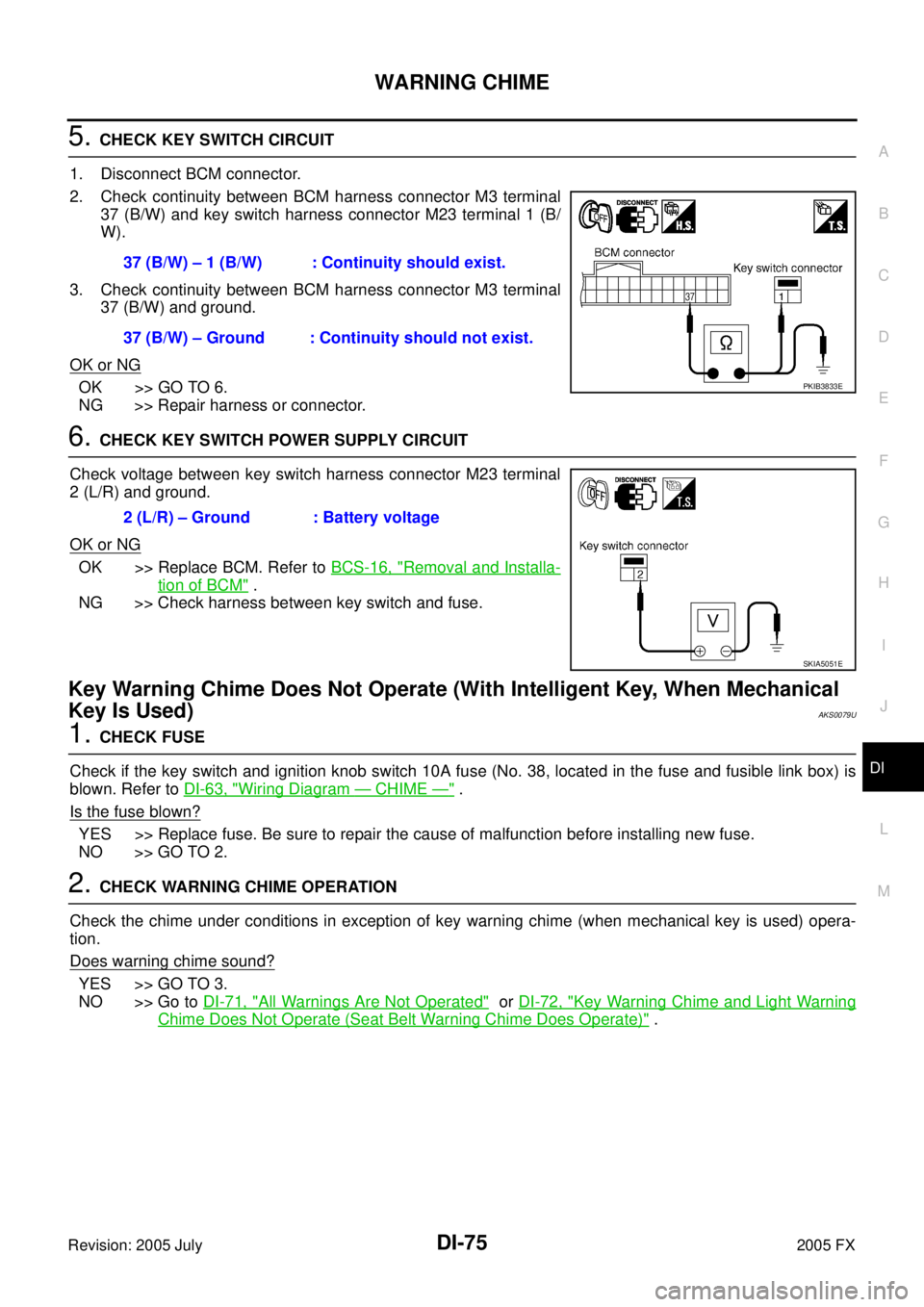
5. CHECK KEY SWITCH CIRCUIT
1. Disconnect BCM connector.
2. Check continuity between BCM harness connector M3 terminal 37 (B/W) and key switch harness connector M23 terminal 1 (B/
W).
3. Check continuity between BCM harness connector M3 terminal 37 (B/W) and ground.
OK or NG
OK >> GO TO 6.
NG >> Repair harness or connector.
6. CHECK KEY SWITCH POWER SUPPLY CIRCUIT
Check voltage between key switch harness connector M23 terminal
2 (L/R) and ground.
OK or NG
OK >> Replace BCM. Refer to BCS-16, "Removal and Installa-
tion of BCM" .
NG >> Check harness between key switch and fuse.
Key Warning Chime Does Not Operate (With Intelligent Key, When Mechanical
Key Is Used)
AKS0079U
1. CHECK FUSE
Check if the key switch and ignition knob switch 10A fuse (No. 38, located in the fuse and fusible link box) is
blown. Refer to DI-63, "
Wiring Diagram — CHIME —" .
Is the fuse blown?
YES >> Replace fuse. Be sure to repair the cause of malfunction before installing new fuse.
NO >> GO TO 2.
2. CHECK WARNING CHIME OPERATION
Check the chime under conditions in exception of key warning chime (when mechanical key is used) opera-
tion.
Does warning chime sound?
YES >> GO TO 3.
NO >> Go to DI-71, "
All Warnings Are Not Operated" or DI-72, "Key Warning Chime and Light Warning
Chime Does Not Operate (Seat Belt Warning Chime Does Operate)" .
37 (B/W) – 1 (B/W) : Continuity should exist.
37 (B/W) – Ground : Continuity should not exist.
PKIB3833E
2 (L/R) – Ground : Battery voltage
SKIA5051E