Page 3060 of 4731
![INFINITI FX35 2005 Service Manual OIL SEAL EM-225
[VK45DE]
C
D E
F
G H
I
J
K L
M A
EM
Revision: 2005 July 2005 FX
OIL SEALPFP:00100
Removal and Installation of Valve Oil SealABS006IM
REMOVAL
1. Remove engine assembly from](/manual-img/42/57020/w960_57020-3059.png "INFINITI FX35 2005 Service Manual OIL SEAL EM-225
[VK45DE]
C
D E
F
G H
I
J
K L
M A
EM
Revision: 2005 July 2005 FX
OIL SEALPFP:00100
Removal and Installation of Valve Oil SealABS006IM
REMOVAL
1. Remove engine assembly from")
OIL SEAL EM-225
[VK45DE]
C
D E
F
G H
I
J
K L
M A
EM
Revision: 2005 July 2005 FX
OIL SEALPFP:00100
Removal and Installation of Valve Oil SealABS006IM
REMOVAL
1. Remove engine assembly from vehicle. Refer to EM-240, "ENGINE ASSEMBLY" .
2. Remove camshaft relating to valve oil seal to be removed. Refer to EM-212, "
CAMSHAFT" .
3. Remove adjusting shims and valve lifters. Refer to EM-212, "
CAMSHAFT" .
�Identify installation positions, and store them without mixing them up.
4. Turn crankshaft until the cylinder requiring new oil seals is at TDC. This will prevent valve from dropping into cylinder.
5. Remove valve collet.
�Compress valve spring with valve spring compressor, attach-
ment and adapter (SST). Remove valve collet with magnetic
hand.
CAUTION:
When working, take care not to damage valve lifter holes.
6. Remove valve spring retainer and valve spring (with valve spring seat). CAUTION:
Do not remove valve spring seat from valve spring.
7. Remove valve oil seal using valve oil seal puller (SST).
INSTALLATION
1. Apply new engine oil on new valve oil seal joint and seal lip.
2. Install valve oil seal.
�Install with valve oil seal drift (SST) to match dimension in the
figure.
3. Install in the reverse order of removal.
PBIC2360E
PBIC0072E
PBIC0073E
Page 3061 of 4731
![INFINITI FX35 2005 Service Manual EM-226
[VK45DE]
OIL SEAL
Revision: 2005 July 2005 FX
Removal and Installation of Front Oil SealABS006IN
REMOVAL
1. Remove the following parts:
�Front engine undercover
�Radiator; Refer to CO-41, "RADI](/manual-img/42/57020/w960_57020-3060.png "INFINITI FX35 2005 Service Manual EM-226
[VK45DE]
OIL SEAL
Revision: 2005 July 2005 FX
Removal and Installation of Front Oil SealABS006IN
REMOVAL
1. Remove the following parts:
�Front engine undercover
�Radiator; Refer to CO-41, \"RADI")
EM-226
[VK45DE]
OIL SEAL
Revision: 2005 July 2005 FX
Removal and Installation of Front Oil SealABS006IN
REMOVAL
1. Remove the following parts:
�Front engine undercover
�Radiator; Refer to CO-41, "RADIATOR"
�Drive belt; Refer to EM-173, "DRIVE BELTS" .
�Cooling fan; Refer to CO-49, "COOLING FAN" .
�Rear plate cover; Refer to EM-185, "OIL PAN AND OIL STRAINER" .
2. Remove crankshaft pulley as follows:
a. Set ring gear stopper (SST).
b. Loosen crankshaft pulley bolt, and then pull crankshaft pulley with both hands to remove it.
CAUTION:
�Do not remove crankshaft pulley bolt. Keep loosened
crankshaft pulley bolt in place to protect removed crank-
shaft pulley from dropping.
�Do not remove balance weight (inner hexagon bolt) at the
front of crankshaft pulley.
3. Remove front oil seal using suitable tool. CAUTION:
Be careful not to damage front cover and oil pump drive
spacer.
INSTALLATION
1. Apply new engine oil to both oil seal lip and dust seal lip of new front oil seal.
2. Install front oil seal.
PBIC1656E
SBIA0358E
SBIA0359E
Page 3062 of 4731
![INFINITI FX35 2005 Service Manual OIL SEAL EM-227
[VK45DE]
C
D E
F
G H
I
J
K L
M A
EM
Revision: 2005 July 2005 FX
�Install front oil seal so that each seal lip is oriented as shown
in the figure.
�Using front oil seal dr](/manual-img/42/57020/w960_57020-3061.png "INFINITI FX35 2005 Service Manual OIL SEAL EM-227
[VK45DE]
C
D E
F
G H
I
J
K L
M A
EM
Revision: 2005 July 2005 FX
�Install front oil seal so that each seal lip is oriented as shown
in the figure.
�Using front oil seal dr")
OIL SEAL EM-227
[VK45DE]
C
D E
F
G H
I
J
K L
M A
EM
Revision: 2005 July 2005 FX
�Install front oil seal so that each seal lip is oriented as shown
in the figure.
�Using front oil seal drift, press fit until the height of front oil
seal is level with the mounting surface.
�Make sure the garter spring is in position and seal lips not
inverted.
CAUTION:
�Be careful not to damage front cover and oil pump drive
spacer.
�Press fit straight and avoid causing burrs or tilting oil seal.
3. Install in the reverse order of removal.
Removal and Installation of Rear Oil SealABS006IO
REMOVAL
1. Remove transmission (with transfer) assembly. Refer to AT- 2 7 0 , "TRANSMISSION ASSEMBLY" .
a. Remove drive plate. Refer to EM-245, "
CYLINDER BLOCK" .
b. Remove engine rear plate. Refer to EM-245, "
CYLINDER BLOCK" .
2. Remove rear oil seal using suitable tool. CAUTION:
Be careful not to damage crankshaft and oil seal retainer
surface.
INSTALLATION
1. Apply new engine oil to both oil seal lip and dust seal lip of new rear oil seal.
2. Install rear oil seal.
�Install rear oil seal so that each seal lip is oriented as shown
in the figure.
SEM715A
Front oil seal drift
Outer diameter : 56 mm (2.20 in)
Inner diameter : 49 mm (1.93 in)
SBIA0359E
SBIA0360E
SEM715A
Page 3063 of 4731
EM-228
[VK45DE]
OIL SEAL
Revision: 2005 July 2005 FX
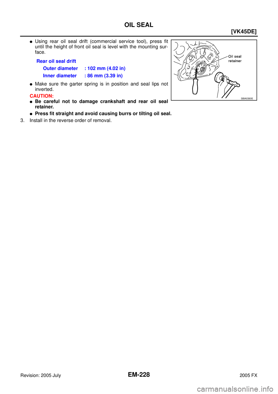
�Using rear oil seal drift (commercial service tool), press fit
until the height of front oil seal is level with the mounting sur-
face.
�Make sure the garter spring is in position and seal lips not
inverted.
CAUTION:
�Be careful not to damage crankshaft and rear oil seal
retainer.
�Press fit straight and avoid causing burrs or tilting oil seal.
3. Install in the reverse order of removal. Rear oil seal drift
Outer diameter : 102 mm (4.02 in)
Inner diameter : 86 mm (3.39 in)
SBIA0360E
Page 3064 of 4731
![INFINITI FX35 2005 Service Manual CYLINDER HEAD EM-229
[VK45DE]
C
D E
F
G H
I
J
K L
M A
EM
Revision: 2005 July 2005 FX
CYLINDER HEADPFP:11041
On-Vehicle ServiceABS006IP
CHECKING COMPRESSION PRESSURE
1. Warm up engine thor](/manual-img/42/57020/w960_57020-3063.png "INFINITI FX35 2005 Service Manual CYLINDER HEAD EM-229
[VK45DE]
C
D E
F
G H
I
J
K L
M A
EM
Revision: 2005 July 2005 FX
CYLINDER HEADPFP:11041
On-Vehicle ServiceABS006IP
CHECKING COMPRESSION PRESSURE
1. Warm up engine thor")
CYLINDER HEAD EM-229
[VK45DE]
C
D E
F
G H
I
J
K L
M A
EM
Revision: 2005 July 2005 FX
CYLINDER HEADPFP:11041
On-Vehicle ServiceABS006IP
CHECKING COMPRESSION PRESSURE
1. Warm up engine thoroughly. Then, stop it.
2. Release fuel pressure. Refer to EC-789, "
FUEL PRESSURE RELEASE" .
a. Remove fuel pump fuse to avoid fuel injection during measure- ment.
3. Remove engine cover with power tool. Refer to EM-172, "
ENGINE ROOM COVER" .
4. Remove ignition coil and spark plug from each cylinder. Refer to EM-189, "
IGNITION COIL" and EM-190,
"SPARK PLUG (PLATINUM-TIPPED TYPE)" .
5. Connect engine tachometer (not required in use of CONSULT-II).
6. Install compression gauge with adapter (SST or commercial ser- vice tool) onto spark plug hole.
�Use compression gauge adapter (SST) which is required on
No. 7 and 8 cylinders.
�Use compression gauge adapter (if no SST is used) whose
picking up end inserted to spark plug hole is smaller than 20
mm (0.79 in) in diameter. Otherwise, it may be caught by cyl-
inder head during removal.
7. With accelerator pedal fully depressed, turn ignition switch to “START” for cranking. When the gauge pointer stabilizes, read the compression pressure and engine rpm. Perform these steps to check each cyl-
inder.
Compression pressure:
Unit: kPa (kg/cm2 , psi) /rpm
CAUTION:
Always use a fully changed battery to obtain the specified engine speed.
PBIB1482E
PBIC1554E
SBIA0533E
Standard Minimum Deferential limit between cylinders
1,320 (13.5, 191) / 300 1,130 (11.5, 164) / 300 98 (1.0, 14) / 300
Page 3065 of 4731
![INFINITI FX35 2005 Service Manual EM-230
[VK45DE]
CYLINDER HEAD
Revision: 2005 July 2005 FX
�If the engine speed is out of specified range, check battery liquid for proper gravity. Check engine
speed again with normal battery gravity](/manual-img/42/57020/w960_57020-3064.png "INFINITI FX35 2005 Service Manual EM-230
[VK45DE]
CYLINDER HEAD
Revision: 2005 July 2005 FX
�If the engine speed is out of specified range, check battery liquid for proper gravity. Check engine
speed again with normal battery gravity")
EM-230
[VK45DE]
CYLINDER HEAD
Revision: 2005 July 2005 FX
�If the engine speed is out of specified range, check battery liquid for proper gravity. Check engine
speed again with normal battery gravity.
�If compression pressure is below minimum value, check valve clearances and parts associated with
combustion chamber (valve, valve seat, piston, piston ring, cylinder bore, cylinder head, cylinder head
gasket). After the checking, measure compression pressure again.
�If some cylinders have low compression pressure, pour small amount of engine oil into the spark plug
hole of the cylinder to re-check it for compression.
–If the added engine oil improves the compression, piston rings may be worn out or damaged. Check the
piston rings and replace if necessary.
–If the compression pressure remains at low level despite the addition of engine oil, valves may be mal-
functioning. Check valves for damage. Replace valve or valve seat accordingly.
�If two adjacent cylinders have respectively low compression pressure and their compression remains
low even after the addition of engine oil, cylinder head gaskets are leaking. In such a case, replace cyl-
inder head gaskets.
8. After inspection is completed, install removed parts in the reverse order of removal.
9. Start engine, and make sure that engine runs smoothly.
10. Perform trouble diagnosis. If DTC appears, erase it. Refer to EC-791, "
TROUBLE DIAGNOSIS" .
ComponentsABS00DFX
Removal and InstallationABS006IQ
REMOVAL
1. Remove engine assembly from vehicle. Refer to EM-240, "ENGINE ASSEMBLY" .
2. Remove exhaust manifold. Refer to EM-182, "
EXHAUST MANIFOLD AND THREE WAY CATALYST" .
3. Remove camshaft. Refer to EM-212, "
CAMSHAFT" .
1. Engine coolant temperature sensor 2. Washer 3. Cylinder head gasket (left bank)
4. Harness bracket 5. Cylinder head (right bank) 6. Cylinder head bolt
7. Cylinder head gasket (right bank) 8. Cylinder head bolt 9. Cylinder head (left bank)
PBIC2756E
Page 3066 of 4731
![INFINITI FX35 2005 Service Manual CYLINDER HEAD EM-231
[VK45DE]
C
D E
F
G H
I
J
K L
M A
EM
Revision: 2005 July 2005 FX
4. Remove cylinder head bolts in reverse order as shown in the fig-
ure with cylinder head bolt wrenc](/manual-img/42/57020/w960_57020-3065.png "INFINITI FX35 2005 Service Manual CYLINDER HEAD EM-231
[VK45DE]
C
D E
F
G H
I
J
K L
M A
EM
Revision: 2005 July 2005 FX
4. Remove cylinder head bolts in reverse order as shown in the fig-
ure with cylinder head bolt wrenc")
CYLINDER HEAD EM-231
[VK45DE]
C
D E
F
G H
I
J
K L
M A
EM
Revision: 2005 July 2005 FX
4. Remove cylinder head bolts in reverse order as shown in the fig-
ure with cylinder head bolt wrench (commercial service tool) to
remove cylinder heads (right and left banks).
5. Remove cylinder head gaskets.
INSPECTION AFTER REMOVAL
Cylinder Head Bolts Outer Diameter
�Cylinder head bolts are tightened by plastic zone tightening
method. Whenever the size difference between “d1” and “d2”
exceeds the limit, replace them with new one.
�If reduction of outer diameter appears in a position other than
“d2”, use it as “d2” point.
Cylinder Head Distortion
NOTE:
When performing this inspection, cylinder block distortion should be also checking. Refer to EM-265, "
CYLIN-
DER BLOCK DISTORTION" .
1. Using scraper, wipe off oil, scale, gasket, sealant and carbon deposits from surface of cylinder head. CAUTION:
Do not allow gasket fragments to enter engine oil or engine coolant passages.
2. At each of several locations on bottom surface of cylinder head, measure the distortion in six directions.
�If it exceeds the limit, replace cylinder head.
INSTALLATION
1. Install new cylinder head gasket.
2. Turn crankshaft until No. 1 piston is set at TDC.
PBIC0068E
Limit (“d1” – “d2”) : 0.18 mm (0.0071 in)
PBIC2361E
Limit : 0.1 mm (0.004 in)
PBIC0075E
Page 3067 of 4731
![INFINITI FX35 2005 Service Manual EM-232
[VK45DE]
CYLINDER HEAD
Revision: 2005 July 2005 FX
�Crankshaft key should line up with the left bank cylinder cen-
ter line as shown in the figure.
3. Install cylinder head follow the steps b](/manual-img/42/57020/w960_57020-3066.png "INFINITI FX35 2005 Service Manual EM-232
[VK45DE]
CYLINDER HEAD
Revision: 2005 July 2005 FX
�Crankshaft key should line up with the left bank cylinder cen-
ter line as shown in the figure.
3. Install cylinder head follow the steps b")
EM-232
[VK45DE]
CYLINDER HEAD
Revision: 2005 July 2005 FX
�Crankshaft key should line up with the left bank cylinder cen-
ter line as shown in the figure.
3. Install cylinder head follow the steps below to tighten cylinder head bolts in numerical order as shown in the figure with cylin-
der head bolt wrench (commercial service tool).
CAUTION:
If cylinder head bolts are re-used, check their outer diame-
ters before installation. Refer to EM-231, "
Cylinder Head
Bolts Outer Diameter" .
a. Apply new engine oil to threads and seating surface of cylinder head bolts.
b. Tighten all cylinder head bolts. 98.1 N·m (10 kg-m, 72 ft-lb).
c. Completely loosen all cylinder head bolts. CAUTION:
In step “c”, loosen cylinder head bolts in reverse order of that indicated in the figure.
d. Tighten all cylinder head bolts to 44.1 N·m (4.5 kg-m, 33 ft-lb).
e. Turn all cylinder head bolts 60 degrees clockwise. (Angle tight- ening)
CAUTION:
Check the tightening angle by using angle wrench (SST).
Avoid judgment by visual inspection without SST.
�Check tightening angle indicated on angle wrench indicator
plate.
f. Turn all cylinder head bolts 60 degrees clockwise again. (Angle tightening)
4. Install in the reverse order of removal.
PBIC2389E
: 98.1 N·m (10 kg-m, 72 ft-lb)
: 0 N·m (0 kg-m, 0 ft-lb)
: 44 N·m (4.5 kg-m, 33 ft-lb)
PBIC0068E
PBIC0069E