Page 1365 of 4731

DI-104
LANE DEPARTURE WARNING SYSTEM
Revision: 2005 July 2005 FX
Power Supply and Ground Circuit InspectionAKS00C82
1. CHECK FUSE
Check for blown LDW camera unit fuse.
OK or NG
OK >> GO TO 2.
NG >> If fuse is blown, be sure to eliminate cause of malfunction before installing new fuse. Refer to PG-
82, "FUSE BLOCK - JUNCTION BOX (J/B)" .
2. CHECK POWER SUPPLY CIRCUIT
Check voltage between LDW camera unit and ground.
OK or NG
OK >> GO TO 3.
NG >> Check harness between LDW camera unit and fuse.
3. CHECK GROUND CIRCUIT
1. Turn ignition switch OFF.
2. Disconnect LDW camera unit connector.
3. Check continuity between LDW camera unit harness connector R9 terminals 6 (B), 12 (B) and ground.
OK or NG
OK >> Power supply and ground circuit are OK.
NG >> Repair ground harness.
DTC [C1B00] CAMERA UNIT MALFAKS00C7Z
1. CHECK SELF-DIAGNOSIS
1. Perform self-diagnosis.
2. Check if any item other than “[C1B00] CAMERA UNIT” is displayed on self-diagnosis display.
Is any displayed?
YES >> Repair or replace applicable item.
NO >> Replace LDW camera unit.
DTC [C1B01] CAM AIMING INCMPAKS00C80
1. PREFORM CAMERA AIMING ADJUSTMENT
1. Preform camera aiming adjustment. Refer to DI-86, "
Camera Aiming Adjustment" .
2. Erase DTC and perform the LDW camera unit self-diagnosis.
Self
-diagnostic results content
No malfunction detected>>INSPECTION END
Malfunction detected>>Replace LDW camera unit.
Unit Power source Fuse No.
LDW camera unit Ignition switch (ON) 12
Terminals Ignition switch position
(+) (–) OFF ON
Connector Terminal (Wire color)
R9 1 (B/R) Ground 0 V Battery voltage
SKIB1808E
6 (B) – Ground : Continuity should exist.
12 (B) – Ground
SKIB1810E
Page 1366 of 4731
![INFINITI FX35 2005 Service Manual LANE DEPARTURE WARNING SYSTEM DI-105
C
D E
F
G H
I
J
L
M A
B
DI
Revision: 2005 July 2005 FX
DTC [C1B02] VHCL SPD DATA MALFAKS00C7Y
1. CHECK ABS ACTUATOR AND ELECTRIC UNIT (CONTROL UNIT) S](/manual-img/42/57020/w960_57020-1365.png "INFINITI FX35 2005 Service Manual LANE DEPARTURE WARNING SYSTEM DI-105
C
D E
F
G H
I
J
L
M A
B
DI
Revision: 2005 July 2005 FX
DTC [C1B02] VHCL SPD DATA MALFAKS00C7Y
1. CHECK ABS ACTUATOR AND ELECTRIC UNIT (CONTROL UNIT) S")
LANE DEPARTURE WARNING SYSTEM DI-105
C
D E
F
G H
I
J
L
M A
B
DI
Revision: 2005 July 2005 FX
DTC [C1B02] VHCL SPD DATA MALFAKS00C7Y
1. CHECK ABS ACTUATOR AND ELECTRIC UNIT (CONTROL UNIT) SELF-DIAGNOSIS
Perform the ABS actuator and electric unit (control unit) self-diagnosis. Refer to BRC-25, "
CONSULT-II Func-
tions" .
Self
-diagnostic results content
No malfunction detected>>GO TO 2.
Malfunction detected>>Check applicable parts, and repair or replace corresponding parts.
2. TCM SELF-DIAGNOSIS
Perform the TCM self-diagnosis. Refer to AT- 9 0 , "
CONSULT-II Function (A/T)" .
Self
-diagnostic results content
No malfunction detected>>Replace LDW camera unit.
Malfunction detected>>Check applicable parts, and repair or replace corresponding parts.
DTC [C1B03] ABNRML TEMP DETECTAKS00C81
1. COOLING CAMERA UNIT
1. Cooling camera unit.
2. Erase DTC and perform the LDW camera unit self-diagnosis.
Self
-diagnostic results content
No malfunction detected>>INSPECTION END
Malfunction detected>>Replace LDW camera unit.
DTC [U1000] CAN COMM CIRCUITAKS00C7X
1. CHECK CAN COMMUNICATION
1. Select “SELF-DIAG RESULTS” mode for “LDW” with CONSULT-II.
2. Print out CONSULT-II screen.
>> Go to “LAN SYSTEM”. Refer to LAN-5, "
Precautions When Using CONSULT-II" .
DTC [U1010] CONTROL UNIT (CAN)AKS00C9I
Replace LDW camera unit, when “[U1010] CONTROL UNIT (CAN)” is displayed on self-diagnosis display.
Page 1375 of 4731

DI-114
REAR VIEW MONITOR
Revision: 2005 July 2005 FX
REAR VIEW MONITORPFP:28260
System DescriptionAKS0068D
�The rear view monitor is equipped to check the rearward of the vehicle with display when A/T selector
lever is in reverse position.
�The lines of vehicle sides and the distance from the rear end of the vehicle are provided on display as a
guide. It allows the driver to know the distance between the vehicle and a rearward object, and the width
of the vehicle much easier.
POWER SUPPLY AND GROUND
Power is supplied at all time
�through 10A fuse [No. 19, located in fuse block (J/B)]
�to rear view camera control unit terminal 1.
When ignition switch is in ACC or ON position, power is supplied
�through 10A fuse [No. 6, located in fuse block (J/B)]
�to rear view camera control unit terminal 2.
When ignition switch is in ON or START position, power is supplied
�through 10A fuse (No. 83, located in IPDM E/R)
�to back-up lamp relay terminals 2 and 3.
Ground is supplied
�to rear view camera control unit terminal 3
�through grounds M35, M45 and M85.
AV COMMUNICATION LINE
Rear view camera control unit is connected to the following units with AV communication line. Each unit trans-
mits/receives data with AV communication line.
�NAVI control unit
�Display
�Display control unit
�A/C and AV switch
REAR VIEW CAMERA OPERATION
When A/T selector lever is reverse position, power is supplied
�through back-up lamp relay terminal 1
�to TCM terminal 7.
Then back-up lamp relay is energized,
�from back-up lamp relay terminal 5
�to rear view camera control unit terminal 4.
Then, rear view camera control unit is sent camera ON signal
�through rear view camera control unit terminal 8
�to rear view camera terminal 1.
An image taken by rear view camera is sent
�through rear view camera terminals 3 and 4
�to rear view camera control unit terminals 10 and 9.
Then an image is sent
�through rear view camera control unit terminals 12 and 14
�to the display terminals 15 and 16.
An image of rear view will be projected on the display.
Side Distance Guideline
When A/T selector lever is in reverse position, rear view camera control unit is sent rear view camera guideline
image
�through rear view camera control unit terminals 12 and 14
Page 1376 of 4731
REAR VIEW MONITOR DI-115
C
D E
F
G H
I
J
L
M A
B
DI
Revision: 2005 July 2005 FX
�to the display terminals 15 and 16.
Rear view camera guideline will be projected on the display.
Display shows image from rear view camera image and rear view camera guideline.
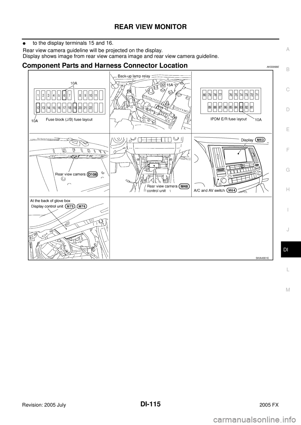
Component Parts and Harness Connector LocationAKS0068E
SKIA4901E
Page 1382 of 4731
AKS007FM
CONSULT-II performs the following functions communicating wit")
REAR VIEW MONITOR DI-121
C
D E
F
G H
I
J
L
M A
B
DI
Revision: 2005 July 2005 FX
CONSULT-II Function (REARVIEW CAMERA)AKS007FM
CONSULT-II performs the following functions communicating with the rear view camera control unit.
CONSULT-II BASIC OPERATION
CAUTION:
If CONSULT-II is used with no connection of CONSULT-II CONVERTER, malfunctions might be
detected in self-diagnosis depending on control unit which carry out CAN communication.
1. With the ignition switch OFF, connect “CONSULT-II” and “CON- SULT-II CONVERTER” to the data link connector, then turn igni-
tion switch ON.
2. Touch “START (NISSAN BASED VHCL)”.
3. Touch “REARVIEW CAMERA” on “SELECT SYSTEM” screen. If “REARVIEW CAMERA” is not indicated, go to GI-39, "
CON-
SULT-II Data Link Connector (DLC) Circuit" .
System Diagnosis mode Description Reference
page
REARVIEW CAMERA Work support
It can adjust the side distance guidelines which overlap the
rear view monitor image. DI-122
Data monitor Displays rear view camera control unit input data in real
time. DI-122
ECU part number Displays part number of rear view camera control unit. —
PBIB1503E
SAIA0450E
PKIB1957E
Page 1383 of 4731

DI-122
REAR VIEW MONITOR
Revision: 2005 July 2005 FX
4. Select “WORK SUPPORT”, “DATA MONITOR” or “ECU PART
NUMBER”.
WORK SUPPORT
Operation Procedure
1. Touch “DATA MONITOR” on “SELECT DIAG MODE” screen.
2. Touch either “SELCT GUIDELINE PATTERN” or “ADJ GUIDELINE POSITION” on the “WORK SUP- PORT” screen.
Refer to DI-123, "
SIDE DISTANCE GUIDELINE CORRECTION PROCEDURE" for detail.
DATA MONITOR
Operation Procedure
1. Touch “DATA MONITOR” on “SELECT DIAG MODE” screen.
2. Touch either “ALL SIGNALS” or “SELECTION FROM MENU” on the “DATA MONITOR” screen.
3. When “SELECTION FROM MENU” is selected, touch individual items to be monitored. When “ALL SIG- NALS” is selected, all items will be monitored.
4. Touch “START”.
5. Touch “RECORD” while monitoring, then the status of the monitored item can be recorded. To stop recording, touch “STOP”.
Display Item List
SKIA5748E
SELCT GUIDELINE PATTERN Side distance guideline is optional from two patterns.
ADJ GUIDELINE POSITION Side distance guideline is adjustable toward up and down, right and left.
ALL SIGNALS Monitors all signals.
SELECTION FROM MENU Selects and monitors individual signal.
Display item [Unit] ALL
SIGNALS SELECTION
FROM MENU Contents
R POSI SIG [ON/OFF] X X Indicates [ON/OFF] condition of R range position signal input.
Page 1387 of 4731

DI-126
REAR VIEW MONITOR
Revision: 2005 July 2005 FX
Rear View Is Not Displayed With The A/T Selector Lever In R-PositionAKS0068N
1. BACK-UP LAMP INSPECTION
1. Turn ignition switch ON.
2. Shift A/T selector lever to R position.
Does back-up lamp illuminate?
YES >> GO TO 2.
NO >> Check back-up lamp system. Refer to LT- 1 2 7 , "
BACK-UP LAMP" in LT section.
2. CHECK REVERSE POSITION INPUT SIGNAL
With CONSULT-II
Select “DATA MONITOR” of “REARVIEW CAMERA”. Operate igni-
tion switch with “R POSI SIG” of “DATA MONITOR” and check oper-
ate status.
Without CONSULT-II
1. Turn ignition switch OFF.
2. Disconnect rear view camera control unit connector.
3. Turn ignition switch ON.
4. Shift A/T selector lever to R position.
5. Check voltage between rear view camera control unit harness connector M48 terminal 4 (OR) and ground.
OK or NG
OK >> GO TO 3.
NG >> Check harness between rear view camera control unit and back-up lamp relay.
3. CHECK DISPLAY CONTROL UNIT OUTPUT SIGNAL
1. Turn ignition switch OFF.
2. Disconnect rear view camera control unit connector.
3. Turn ignition switch ON.
4. Check voltage between rear view camera control unit harness connector M48 terminal 5 (G/Y) and ground.
OK or NG
OK >> GO TO 5.
NG >> GO TO 4.
SKIA7147E
4 (OR) – Ground : Battery voltage
SKIA5086E
5 (G/Y) – Ground : Approx. 5 V
SKIA7148E
Page 1388 of 4731

REAR VIEW MONITOR DI-127
C
D E
F
G H
I
J
L
M A
B
DI
Revision: 2005 July 2005 FX
4. CHECK DISPLAY CONTROL UNIT CIRCUIT
1. Turn ignition switch OFF.
2. Disconnect display control unit connector.
3. Check continuity between rear view camera control unit harness connector M48 terminal 5 (G/Y) and display control unit harness
connector M75 terminal 8 (G/Y).
4. Check continuity between rear view camera control unit harness connector M48 terminal 5 (G/Y) and ground.
OK or NG
OK >> Replace display control unit.
NG >> Repair harness or connector.
5. CHECK CONTROL 1 SIGNAL
1. Turn ignition switch OFF.
2. Connect rear view camera control unit connector.
3. Shift A/T selector lever to R position.
4. Check voltage between rear view camera control unit harness connector M48 terminal 5 (G/Y) and ground.
OK or NG
OK >> GO TO 6.
NG >> Replace rear view camera control unit.
6. CHECK REAR VIEW CAMERA OPEN CIRCUIT
1. Turn ignition switch OFF.
2. Disconnect rear view camera connector.
3. Check continuity between rear view camera control unit harness connector M48 terminal 8 (R/W) and rear view camera harness
connector D108 terminal 1 (PU)
4. Check continuity between rear view camera control unit harness connector M48 terminal 9 and rear view camera harness con-
nector D108 terminal 4
5. Check continuity between rear view camera control unit harness connector M48 terminal 10 (G/W) and rear view camera harness
connector D108 terminal 3 (G)
OK or NG
OK >> GO TO 7.
NG >> Repair harness or connector. 5 (G/Y) – 8 (G/Y) : Continuity should exist.
5 (G/Y) – Ground : Continuity should not exist.
SKIA7149E
5 (G/Y) – Ground : Approx. 0 V
SKIA7150E
8 (R/W) – 1 (PU) : Continuity should exist.
9 – 4 : Continuity should exist.
10 (G/W) – 3 (G) : Continuity should exist.
SKIA5095E