Page 4145 of 4731
MA-18
ENGINE MAINTENANCE (VQ35DE ENGINE)
Revision: 2005 July 2005 FX
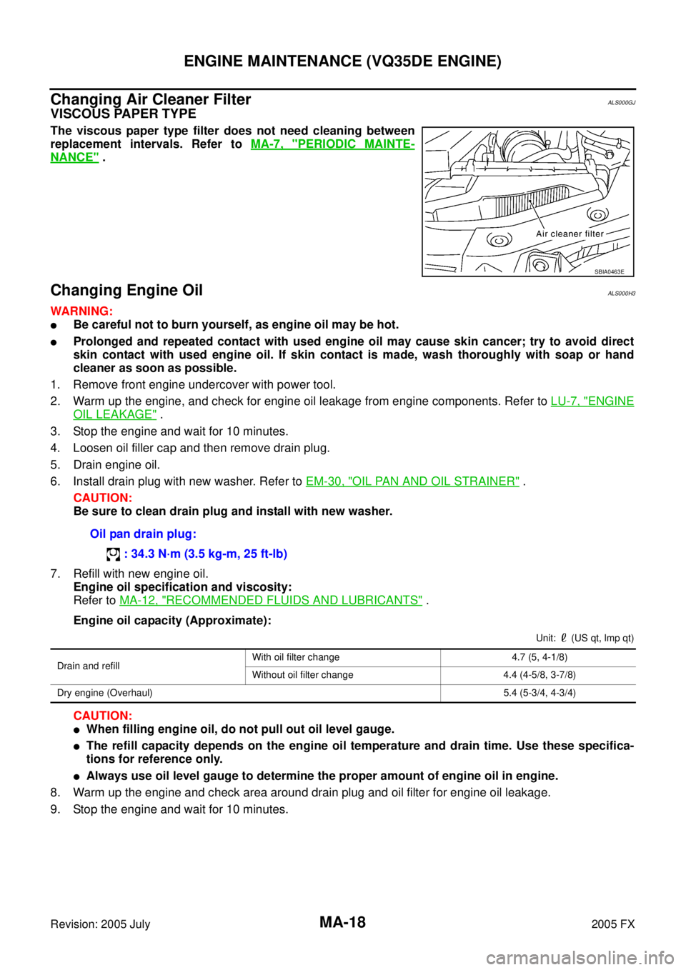
Changing Air Cleaner FilterALS000GJ
VISCOUS PAPER TYPE
The viscous paper type filter does not need cleaning between
replacement intervals. Refer to MA-7, "
PERIODIC MAINTE-
NANCE" .
Changing Engine OilALS000H3
WARNING:
�Be careful not to burn yourself, as engine oil may be hot.
�Prolonged and repeated contact with used engine oil may cause skin cancer; try to avoid direct
skin contact with used engine oil. If skin contact is made, wash thoroughly with soap or hand
cleaner as soon as possible.
1. Remove front engine undercover with power tool.
2. Warm up the engine, and check for engine oil leakage from engine components. Refer to LU-7, "
ENGINE
OIL LEAKAGE" .
3. Stop the engine and wait for 10 minutes.
4. Loosen oil filler cap and then remove drain plug.
5. Drain engine oil.
6. Install drain plug with new washer. Refer to EM-30, "
OIL PAN AND OIL STRAINER" .
CAUTION:
Be sure to clean drain plug and install with new washer.
7. Refill with new engine oil. Engine oil specification and viscosity:
Refer to MA-12, "
RECOMMENDED FLUIDS AND LUBRICANTS" .
Engine oil capacity (Approximate):
Unit: (US qt, lmp qt)
CAUTION:
�When filling engine oil, do not pull out oil level gauge.
�The refill capacity depends on the engine oil temperature and drain time. Use these specifica-
tions for reference only.
�Always use oil level gauge to determine the proper amount of engine oil in engine.
8. Warm up the engine and check area around drain plug and oil filter for engine oil leakage.
9. Stop the engine and wait for 10 minutes.
SBIA0463E
Oil pan drain plug:
: 34.3 N·m (3.5 kg-m, 25 ft-lb)
Drain and refill With oil filter change 4.7 (5, 4-1/8)
Without oil filter change 4.4 (4-5/8, 3-7/8)
Dry engine (Overhaul) 5.4 (5-3/4, 4-3/4)
Page 4146 of 4731
ENGINE MAINTENANCE (VQ35DE ENGINE) MA-19
C
D E
F
G H
I
J
K
M A
B
MA
Revision: 2005 July 2005 FX
10. Check the engine oil level.
Changing Oil FilterALS000GL
REMOVAL
WARNING:
Be careful not to get burned when the engine and engine oil may be hot.
1. Remove front engine undercover with power tool.
2. Using oil filter wrench [SST], remove oil filter. CAUTION:
�Oil filter is provided with relief valve. Use Genuine Nissan
Oil Filter or equivalent.
�When removing, prepare a shop cloth to absorb any
engine oil leakage or spillage.
�Do not allow engine oil to adhere to drive belts.
�Completely wipe off any engine oil that adheres to engine
and vehicle.
INSTALLATION
1. Remove foreign materials adhering to oil filter installation surface.
2. Apply engine oil to the oil seal contact surface of new oil filter.
PBIC0249E
SBIA0454E
SBIA0455E
SMA010
Page 4149 of 4731
MA-22
ENGINE MAINTENANCE (VK45DE ENGINE)
Revision: 2005 July 2005 FX
ENGINE MAINTENANCE (VK45DE ENGINE)PFP:10001
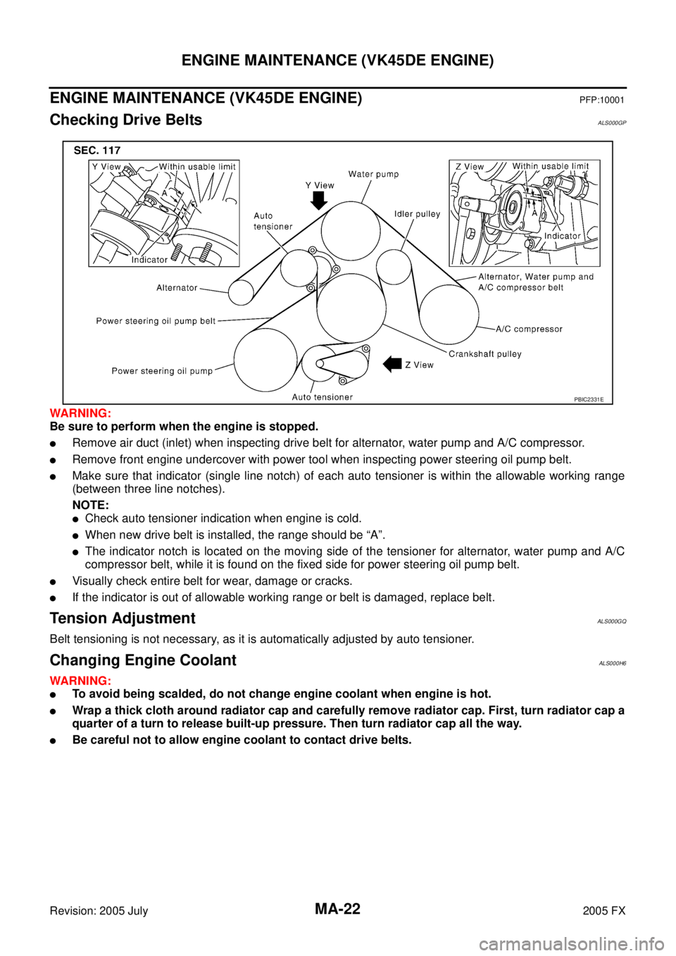
Checking Drive BeltsALS000GP
WARNING:
Be sure to perform when the engine is stopped.
�Remove air duct (inlet) when inspecting drive belt for alternator, water pump and A/C compressor.
�Remove front engine undercover with power tool when inspecting power steering oil pump belt.
�Make sure that indicator (single line notch) of each auto tensioner is within the allowable working range
(between three line notches).
NOTE:
�Check auto tensioner indication when engine is cold.
�When new drive belt is installed, the range should be “A”.
�The indicator notch is located on the moving side of the tensioner for alternator, water pump and A/C
compressor belt, while it is found on the fixed side for power steering oil pump belt.
�Visually check entire belt for wear, damage or cracks.
�If the indicator is out of allowable working range or belt is damaged, replace belt.
Tension AdjustmentALS000GQ
Belt tensioning is not necessary, as it is automatically adjusted by auto tensioner.
Changing Engine CoolantALS000H6
WARNING:
�To avoid being scalded, do not change engine coolant when engine is hot.
�Wrap a thick cloth around radiator cap and carefully remove radiator cap. First, turn radiator cap a
quarter of a turn to release built-up pressure. Then turn radiator cap all the way.
�Be careful not to allow engine coolant to contact drive belts.
PBIC2331E
Page 4152 of 4731
ENGINE MAINTENANCE (VK45DE ENGINE) MA-25
C
D E
F
G H
I
J
K
M A
B
MA
Revision: 2005 July 2005 FX
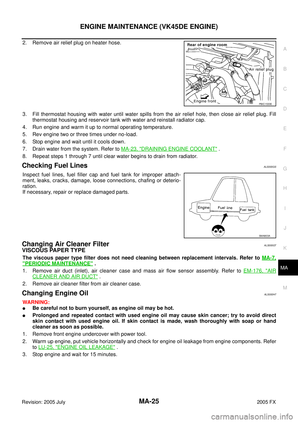
2. Remove air relief plug on heater hose.
3. Fill thermostat housing with water until water spills from the air relief hole, then close air relief plug. Fill
thermostat housing and reservoir tank with water and reinstall radiator cap.
4. Run engine and warm it up to normal operating temperature.
5. Rev engine two or three times under no-load.
6. Stop engine and wait until it cools down.
7. Drain water from the system. Refer to MA-23, "
DRAINING ENGINE COOLANT" .
8. Repeat steps 1 through 7 until clear water begins to drain from radiator.
Checking Fuel LinesALS000GS
Inspect fuel lines, fuel filler cap and fuel tank for improper attach-
ment, leaks, cracks, damage, loose connections, chafing or deterio-
ration.
If necessary, repair or replace damaged parts.
Changing Air Cleaner FilterALS000GT
VISCOUS PAPER TYPE
The viscous paper type filter does not need cleaning between replacement intervals. Refer to MA-7,
"PERIODIC MAINTENANCE" .
1. Remove air duct (inlet), air cleaner case and mass air flow sensor assembly. Refer to EM-176, "
AIR
CLEANER AND AIR DUCT" .
2. Remove air cleaner filter from air cleaner case.
Changing Engine OilALS000H7
WARNING:
�Be careful not to burn yourself, as engine oil may be hot.
�Prolonged and repeated contact with used engine oil may cause skin cancer; try to avoid direct
skin contact with used engine oil. If skin contact is made, wash thoroughly with soap or hand
cleaner as soon as possible.
1. Remove front engine undercover with power tool.
2. Warm up engine, put vehicle horizontally and check for engine oil leakage from engine components. Refer to LU-25, "
ENGINE OIL LEAKAGE" .
3. Stop engine and wait for 15 minutes.
PBIC1530E
SMA803A
Page 4153 of 4731
MA-26
ENGINE MAINTENANCE (VK45DE ENGINE)
Revision: 2005 July 2005 FX
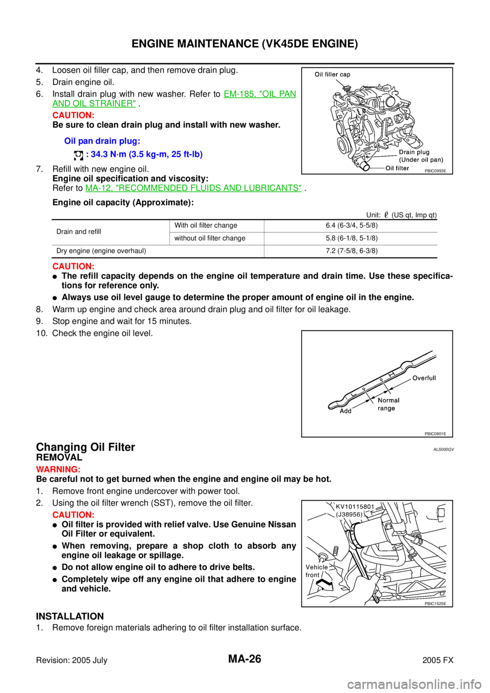
4. Loosen oil filler cap, and then remove drain plug.
5. Drain engine oil.
6. Install drain plug with new washer. Refer to EM-185, "
OIL PAN
AND OIL STRAINER" .
CAUTION:
Be sure to clean drain plug and install with new washer.
7. Refill with new engine oil. Engine oil specification and viscosity:
Refer to MA-12, "
RECOMMENDED FLUIDS AND LUBRICANTS" .
Engine oil capacity (Approximate):
Unit: (US qt, Imp qt)
CAUTION:
�The refill capacity depends on the engine oil temperature and drain time. Use these specifica-
tions for reference only.
�Always use oil level gauge to determine the proper amount of engine oil in the engine.
8. Warm up engine and check area around drain plug and oil filter for oil leakage.
9. Stop engine and wait for 15 minutes.
10. Check the engine oil level.
Changing Oil FilterALS000GV
REMOVAL
WARNING:
Be careful not to get burned when the engine and engine oil may be hot.
1. Remove front engine undercover with power tool.
2. Using the oil filter wrench (SST), remove the oil filter. CAUTION:
�Oil filter is provided with relief valve. Use Genuine Nissan
Oil Filter or equivalent.
�When removing, prepare a shop cloth to absorb any
engine oil leakage or spillage.
�Do not allow engine oil to adhere to drive belts.
�Completely wipe off any engine oil that adhere to engine
and vehicle.
INSTALLATION
1. Remove foreign materials adhering to oil filter installation surface. Oil pan drain plug:
: 34.3 N·m (3.5 kg-m, 25 ft-lb)
PBIC0993E
Drain and refill With oil filter change 6.4 (6-3/4, 5-5/8)
without oil filter change 5.8 (6-1/8, 5-1/8)
Dry engine (engine overhaul) 7.2 (7-5/8, 6-3/8)
PBIC0801E
PBIC1525E
Page 4171 of 4731
PB-2
PARKING BRAKE SYSTEM
Revision: 2005 July 2005 FX
PARKING BRAKE SYSTEMPFP:36010
On-Vehicle ServiceAFS001TJ
PEDAL STROKE
�When parking brake pedal is operated with a force of 200 N (20.4 kg, 44.9 lb), make sure the stroke is
within the specified number of notches. (Check it by listening and counting the ratchet clicks.)
INSPECT COMPONENTS
�Make sure the components are attached properly (check for looseness, backlash, etc.).
�Check parking brake pedal assembly for bend, damage and cracks, and replace if necessary.
�Check cable for wear and damage, and replace if necessary.
�Check parking brake warning lamp switch for malfunction, and replace if necessary.
ADJUSTMENT
�To perform adjustment operations, remove tire from the vehicle with power tool.
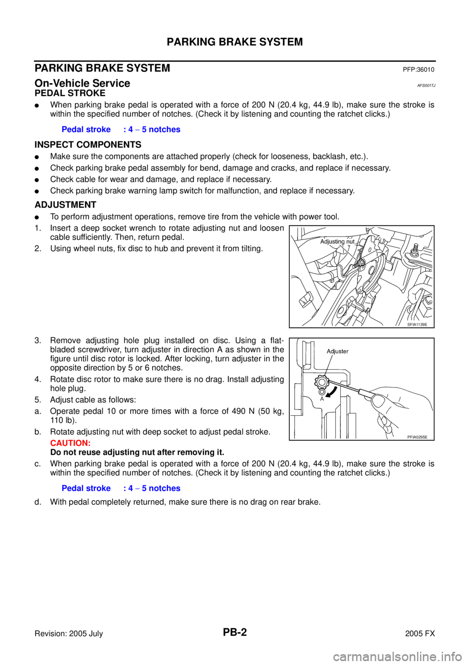
1. Insert a deep socket wrench to rotate adjusting nut and loosen cable sufficiently. Then, return pedal.
2. Using wheel nuts, fix disc to hub and prevent it from tilting.
3. Remove adjusting hole plug installed on disc. Using a flat- bladed screwdriver, turn adjuster in direction A as shown in the
figure until disc rotor is locked. After locking, turn adjuster in the
opposite direction by 5 or 6 notches.
4. Rotate disc rotor to make sure there is no drag. Install adjusting hole plug.
5. Adjust cable as follows:
a. Operate pedal 10 or more times with a force of 490 N (50 kg, 11 0 l b ) .
b. Rotate adjusting nut with deep socket to adjust pedal stroke. CAUTION:
Do not reuse adjusting nut after removing it.
c. When parking brake pedal is operated with a force of 200 N (20.4 kg, 44.9 lb), make sure the stroke is within the specified number of notches. (Check it by listening and counting the ratchet clicks.)
d. With pedal completely returned, make sure there is no drag on rear brake. Pedal stroke : 4
− 5 notches
SFIA1139E
Pedal stroke : 4 − 5 notches
PFIA0295E
Page 4174 of 4731
PARKING BRAKE SHOE PB-5
C
D E
G H
I
J
K L
M A
B
PB
Revision: 2005 July 2005 FX
PARKING BRAKE SHOEPFP:44060
ComponentsAFS001TM
Removal and InstallationAFS001TN
REMOVAL
WARNING:
Clean brakes with a vacuum dust collector to minimize the hazard of air borne particles or other mate-
rials.
Be careful of the following:
�Remove disc rotor only with parking brake pedal completely in the returned position.
�If disc rotor can not be removed, remove as follows.
1. Fix disc rotor in place with wheel nuts and remove disc rotor plug. Using a flat-bladed screwdriver, rotate adjuster on adjuster
assembly in direction B to retract and loosen brake shoes.
1. Back plate 2. Anchor block 3. Toggle lever
4. Shoe 5. Adjuster 6. Return spring
7. Anti-rattle spring 8. Retainer 9. Anti-rattle pin
SFIA1167E
PFIA0309E
Page 4176 of 4731
SERVICE DATA AND SPECIFICATIONS (SDS) PB-7
C
D E
G H
I
J
K L
M A
B
PB
Revision: 2005 July 2005 FX
SERVICE DATA AND SPECIFICATIONS (SDS)PFP:00030
Parking Drum Brake AFS001TO
Parking Brake ControlAFS001TP
TypeDS19HC
Brake lining Standard thickness (new) 3.2 mm (0.126 in)
Wear limit thickness 1.5 mm (0.059 in)
Drum (disc) Standard inner diameter (new) 190 mm (7.48 in)
Wear limit of inner diameter 191 mm (7.52 in)
Control type Foot pedal
Number of notches [under a force of 200 N (20.4 kg, 44.9 lb)] 4 − 5 notches
Number of notches
when warning lamp switch comes on 1 notches