Page 962 of 4731
INTELLIGENT KEY SYSTEM BL-147
C
D E
F
G H
J
K L
M A
B
BL
Revision: 2005 July 2005 FX
3. CHECK STOP LAMP SWITCH GROUND CIRCUIT
1. Check continuity between stop lamp switch connector E210 ter- minal 2 (P) and Intelligent Key unit connector M34 terminal 26
(P/L).
2. Check continuity between stop lamp switch connector E210 ter- minal 2 (P) and ground.
OK or NG
OK >> Stop lamp switch is OK.
NG >> Repair or replace harness.
Check Detention SwitchAIS004NN
1. CHECK DETENTION SWITCH INPUT SIGNAL
1. Turn ignition knob LOCK position.
2. Check voltage between Intelligent Key unit connector and ground.
OK or NG
OK >> Door switch circuit is OK.
NG >> GO TO 2. 2 (P) - 26 (P/L) : Continuity should exist.
2 (P) - Ground : Continuity should not exist.
PIIA6801E
Connector Terminal
(Wire color) Condition Voltage (V)
(Approx.)
(+) (-)
M34 39 (R/Y) Ground When selector lever is locked
at the “P” position 0
When selector lever is not
locked at the “P” position Battery voltage
PIIA6805E
Page 964 of 4731
INTELLIGENT KEY SYSTEM BL-149
C
D E
F
G H
J
K L
M A
B
BL
Revision: 2005 July 2005 FX
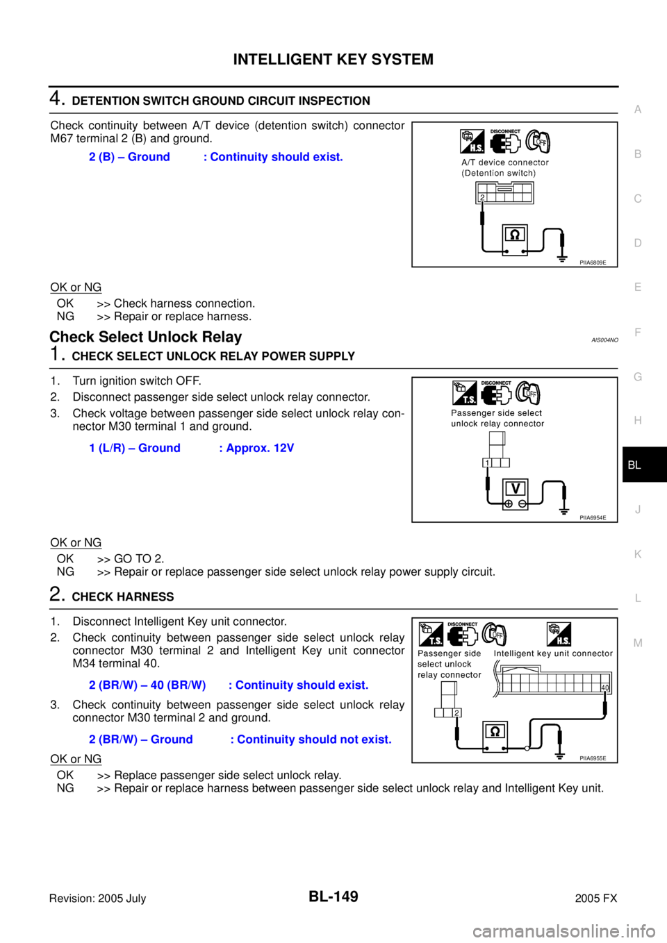
4. DETENTION SWITCH GROUND CIRCUIT INSPECTION
Check continuity between A/T device (detention switch) connector
M67 terminal 2 (B) and ground.
OK or NG
OK >> Check harness connection.
NG >> Repair or replace harness.
Check Select Unlock RelayAIS004NO
1. CHECK SELECT UNLOCK RELAY POWER SUPPLY
1. Turn ignition switch OFF.
2. Disconnect passenger side select unlock relay connector.
3. Check voltage between passenger side select unlock relay con- nector M30 terminal 1 and ground.
OK or NG
OK >> GO TO 2.
NG >> Repair or replace passenger side select unlock relay power supply circuit.
2. CHECK HARNESS
1. Disconnect Intelligent Key unit connector.
2. Check continuity between passenger side select unlock relay connector M30 terminal 2 and Intelligent Key unit connector
M34 terminal 40.
3. Check continuity between passenger side select unlock relay connector M30 terminal 2 and ground.
OK or NG
OK >> Replace passenger side select unlock relay.
NG >> Repair or replace harness between passenger side select unlock relay and Intelligent Key unit. 2 (B) – Ground : Continuity should exist.
PIIA6809E
1 (L/R) – Ground : Approx. 12V
PIIA6954E
2 (BR/W) – 40 (BR/W) : Continuity should exist.
2 (BR/W) – Ground : Continuity should not exist.
PIIA6955E
Page 966 of 4731
INTELLIGENT KEY SYSTEM BL-151
C
D E
F
G H
J
K L
M A
B
BL
Revision: 2005 July 2005 FX
2. CHECK IPDM E/R HARNESS
1. Turn ignition switch OFF.
2. Disconnect IPDM E/R and horn relay connector.
3. Check continuity between IPDM E/R connector E9 terminal 51 (SB) and horn relay connector E10 termi- nal 1 (SB).
OK or NG
OK >> Check harness connection.
NG >> Repair or replace harness.
Removal and Installation of Intelligent Key UnitAIS004NT
REMOVAL
1. Remove the instrument lower driver panel. Refer to IP-11, "Removal and Installation" .
2. Disconnect the Intelligent Key unit connector, remove the screw and Intelligent Key unit.
INSTALLATION
Install in the reverse order of removal. 51 (SB) – 1 (SB) : Continuity should exist.
PIIA6404E
PIIA6371E
Page 991 of 4731
BL-176
BACK DOOR AUTO CLOSURE SYSTEM
Revision: 2005 July 2005 FX
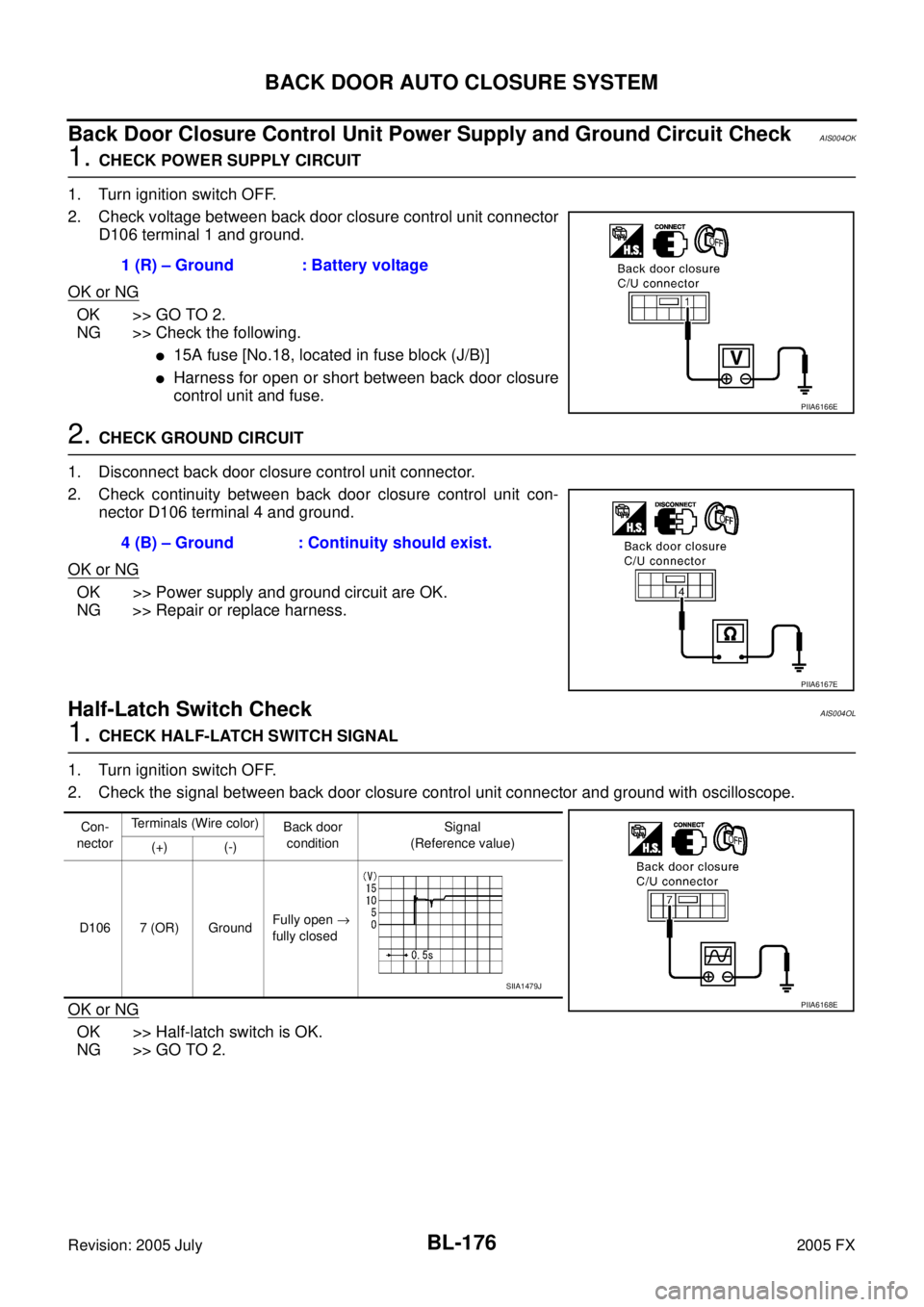
Back Door Closure Control Unit Power Supply and Ground Circuit CheckAIS004OK
1. CHECK POWER SUPPLY CIRCUIT
1. Turn ignition switch OFF.
2. Check voltage between back door closure control unit connector D106 terminal 1 and ground.
OK or NG
OK >> GO TO 2.
NG >> Check the following.
�15A fuse [No.18, located in fuse block (J/B)]
�Harness for open or short between back door closure
control unit and fuse.
2. CHECK GROUND CIRCUIT
1. Disconnect back door closure control unit connector.
2. Check continuity between back door closure control unit con- nector D106 terminal 4 and ground.
OK or NG
OK >> Power supply and ground circuit are OK.
NG >> Repair or replace harness.
Half-Latch Switch CheckAIS004OL
1. CHECK HALF-LATCH SWITCH SIGNAL
1. Turn ignition switch OFF.
2. Check the signal between back door closure control unit connector and ground with oscilloscope.
OK or NG
OK >> Half-latch switch is OK.
NG >> GO TO 2. 1 (R) – Ground : Battery voltage
PIIA6166E
4 (B) – Ground : Continuity should exist.
PIIA6167E
Con-
nector Terminals (Wire color)
Back door
condition Signal
(Reference value)
(+) (-)
D106 7 (OR) Ground Fully open
→
fully closed
PIIA6168E
SIIA1479J
Page 993 of 4731
BL-178
BACK DOOR AUTO CLOSURE SYSTEM
Revision: 2005 July 2005 FX
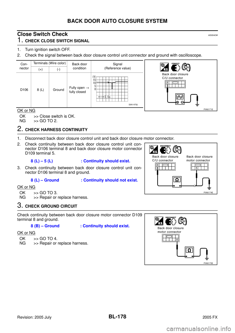
Close Switch CheckAIS004OM
1. CHECK CLOSE SWITCH SIGNAL
1. Turn ignition switch OFF.
2. Check the signal between back door closure control unit connector and ground with oscilloscope.
OK or NG
OK >> Close switch is OK.
NG >> GO TO 2.
2. CHECK HARNESS CONTINUITY
1. Disconnect back door closure control unit and back door closure motor connector.
2. Check continuity between back door closure control unit con- nector D106 terminal 8 and back door closure motor connector
D109 terminal 5.
3. Check continuity between back door closure control unit con- nector D106 terminal 8 and ground.
OK or NG
OK >> GO TO 3.
NG >> Repair or replace harness.
3. CHECK GROUND CIRCUIT
Check continuity between back door closure motor connector D109
terminal 8 and ground.
OK or NG
OK >> GO TO 4.
NG >> Repair or replace harness.
Con-
nector Terminals (Wire color)
Back door
condition Signal
(Reference value)
(+) (-)
D106 8 (L) Ground Fully open
→
fully closed
PIIA6171E
SIIA1478J
8 (L) – 5 (L) : Continuity should exist.
8 (L) – Ground : Continuity should not exist.
PIIA6174E
8 (B) – Ground : Continuity should exist.
PIIA6170E
Page 994 of 4731

BACK DOOR AUTO CLOSURE SYSTEM BL-179
C
D E
F
G H
J
K L
M A
B
BL
Revision: 2005 July 2005 FX
4. CHECK BACK DOOR CLOSURE CONTROL UNIT OUTPUT SIGNAL
1. Connect back door closure control unit connector.
2. Check voltage between back door closure control unit connector D106 terminal 8 and ground.
OK or NG
OK >> Replace back door lock assembly.
NG >> Replace back door closure control unit.
Open Switch CheckAIS004ON
1. CHECK OPEN SWITCH SIGNAL
1. Turn ignition switch OFF.
2. Check the signal between back door closure control unit connector and ground with oscilloscope.
OK or NG
OK >> Open switch is OK.
NG >> GO TO 2.
2. CHECK HARNESS CONTINUITY
1. Disconnect back door closure control unit and back door closure motor connector.
2. Check continuity between back door closure control unit con- nector D106 terminal 9 and back door closure motor connector
D109 terminal 4.
3. Check continuity between back door closure control unit con- nector D106 terminal 9 and ground.
OK or NG
OK >> GO TO 3.
NG >> Repair or replace harness. Back door is closed
8 (L) – Ground : Battery voltage
PIIA6173E
Con-
nector Terminals (Wire color)
Back door
condition Signal
(Reference value)
(+) (-)
D106 9 (P) Ground Fully open
→
fully closed
PIIA6175E
SIIA1481J
9 (P) – 4 (P) : Continuity should exist.
9 (P) – Ground : Continuity should not exist.
PIIA6176E
Page 995 of 4731
BL-180
BACK DOOR AUTO CLOSURE SYSTEM
Revision: 2005 July 2005 FX
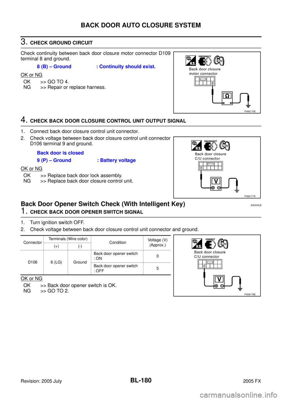
3. CHECK GROUND CIRCUIT
Check continuity between back door closure motor connector D109
terminal 8 and ground.
OK or NG
OK >> GO TO 4.
NG >> Repair or replace harness.
4. CHECK BACK DOOR CLOSURE CONTROL UNIT OUTPUT SIGNAL
1. Connect back door closure control unit connector.
2. Check voltage between back door closure control unit connector D106 terminal 9 and ground.
OK or NG
OK >> Replace back door lock assembly.
NG >> Replace back door closure control unit.
Back Door Opener Switch Check (With Intelligent Key)AIS004U8
1. CHECK BACK DOOR OPENER SWITCH SIGNAL
1. Turn ignition switch OFF.
2. Check voltage between back door closure control unit connector and ground.
OK or NG
OK >> Back door opener switch is OK.
NG >> GO TO 2. 8 (B) – Ground : Continuity should exist.
PIIA6170E
Back door is closed
9 (P) – Ground : Battery voltage
PIIA6177E
Connector Terminals (Wire color)
Condition Voltage (V)
(Approx.)
(+) (-)
D106 6 (LG) Ground Back door opener switch
: ON 0
Back door opener switch
: OFF 5
PIIA6178E
Page 997 of 4731
BL-182
BACK DOOR AUTO CLOSURE SYSTEM
Revision: 2005 July 2005 FX
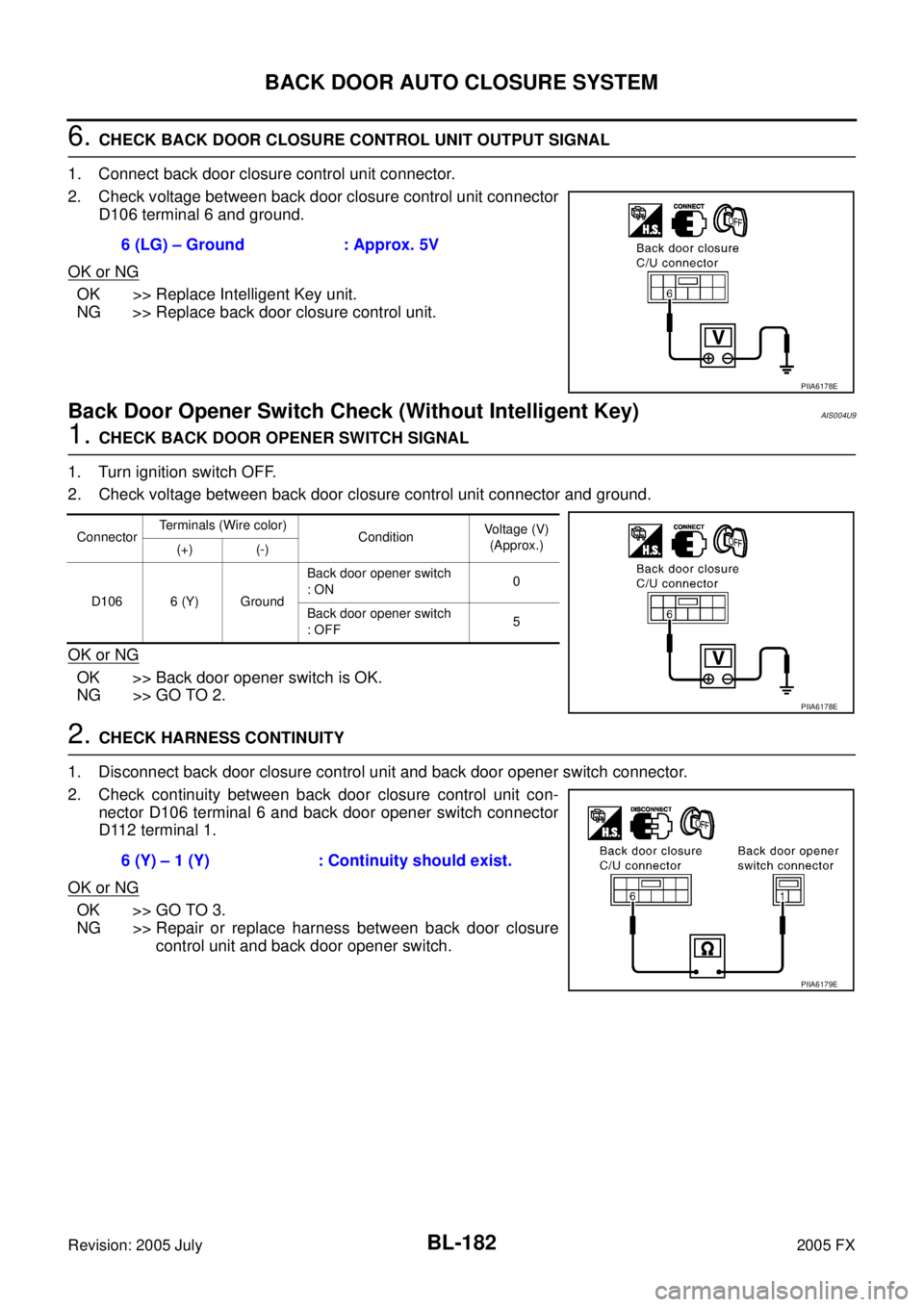
6. CHECK BACK DOOR CLOSURE CONTROL UNIT OUTPUT SIGNAL
1. Connect back door closure control unit connector.
2. Check voltage between back door closure control unit connector D106 terminal 6 and ground.
OK or NG
OK >> Replace Intelligent Key unit.
NG >> Replace back door closure control unit.
Back Door Opener Switch Check (Without Intelligent Key)AIS004U9
1. CHECK BACK DOOR OPENER SWITCH SIGNAL
1. Turn ignition switch OFF.
2. Check voltage between back door closure control unit connector and ground.
OK or NG
OK >> Back door opener switch is OK.
NG >> GO TO 2.
2. CHECK HARNESS CONTINUITY
1. Disconnect back door closure control unit and back door opener switch connector.
2. Check continuity between back door closure control unit con- nector D106 terminal 6 and back door opener switch connector
D112 terminal 1.
OK or NG
OK >> GO TO 3.
NG >> Repair or replace harness between back door closure control unit and back door opener switch.
6 (LG) – Ground : Approx. 5V
PIIA6178E
Connector
Terminals (Wire color)
Condition Voltage (V)
(Approx.)
(+) (-)
D106 6 (Y) Ground Back door opener switch
: ON 0
Back door opener switch
: OFF 5
PIIA6178E
6 (Y) – 1 (Y) : Continuity should exist.
PIIA6179E