Page 2884 of 4731
![INFINITI FX35 2005 Service Manual FUEL INJECTOR AND FUEL TUBE EM-49
[VQ35DE]
C
D E
F
G H
I
J
K L
M A
EM
Revision: 2005 July 2005 FX
�Tighten mounting bolts in two steps in numerical order as
shown in the figure.
6. Conn](/manual-img/42/57020/w960_57020-2883.png "INFINITI FX35 2005 Service Manual FUEL INJECTOR AND FUEL TUBE EM-49
[VQ35DE]
C
D E
F
G H
I
J
K L
M A
EM
Revision: 2005 July 2005 FX
�Tighten mounting bolts in two steps in numerical order as
shown in the figure.
6. Conn")
FUEL INJECTOR AND FUEL TUBE EM-49
[VQ35DE]
C
D E
F
G H
I
J
K L
M A
EM
Revision: 2005 July 2005 FX
�Tighten mounting bolts in two steps in numerical order as
shown in the figure.
6. Connect injector sub-harness.
7. Install intake manifold collectors (upper and lower). Refer to EM-19, "
INTAKE MANIFOLD COLLECTOR" .
8. Install fuel sub-tube on rear end of intake manifold collector (lower).
9. Connect fuel feed hose (with damper).
�Handling procedure of O-ring is the same as that of fuel damper and fuel sub-tube.
�Insert fuel damper straight into fuel sub-tube.
�Tighten mounting bolts evenly in turn.
�After tightening mounting bolts, make sure that there is no gap between flange and fuel sub-tube.
10. Connect quick connector between fuel feed hose (with damper) and centralized under-floor piping con- nection as follows:
a. Make sure no foreign substances are deposited in and around centralized under-floor piping and quick connector, and no damage on them.
b. Thinly apply new engine oil around centralized under-floor piping from tip end to spool end.
c. Align center to insert quick connector straightly into centralized under-floor piping.
�Insert quick connector to centralized under-floor piping until
top spool is completely inside quick connector, and 2nd level
spool exposes right below quick connector.
CAUTION:
�Hold “A” position as shown in the figure when inserting
centralized under-floor piping into quick connector.
�Carefully align center to avoid inclined insertion to pre-
vent damage to O-ring inside quick connector.
�Insert until you hear a “click” sound and actually feel the
engagement.
�To avoid misidentification of engagement with a similar
sound, be sure to perform the next step.
d. Pull quick connector by hand holding “A” position. Make sure it is completely engaged (connected) so that it does not come out from centralized under-floor piping.
e. Install quick connector cap to quick connector connection.
�Install quick connector cap with arrow on surface facing in
direction of quick connector (fuel feed hose side).
CAUTION:
If quick connector cap cannot be installed smoothly, quick
connector may have not been installed correctly. Check the
connection again.
11. Install in the reverse order of removal after this step. 1st step
: 10.1 N·m (1.0 kg-m, 7 ft-lb)
2nd step : 23.6 N·m (2.4 kg-m, 17 ft-lb)
KBIA1296E
PBIC2471E
KBIA1298E
Page 2886 of 4731
![INFINITI FX35 2005 Service Manual ROCKER COVER EM-51
[VQ35DE]
C
D E
F
G H
I
J
K L
M A
EM
Revision: 2005 July 2005 FX
ROCKER COVERPFP:13264
ComponentsABS00E64
Removal and InstallationABS004U9
REMOVAL
1. Remove engine cover](/manual-img/42/57020/w960_57020-2885.png "INFINITI FX35 2005 Service Manual ROCKER COVER EM-51
[VQ35DE]
C
D E
F
G H
I
J
K L
M A
EM
Revision: 2005 July 2005 FX
ROCKER COVERPFP:13264
ComponentsABS00E64
Removal and InstallationABS004U9
REMOVAL
1. Remove engine cover")
ROCKER COVER EM-51
[VQ35DE]
C
D E
F
G H
I
J
K L
M A
EM
Revision: 2005 July 2005 FX
ROCKER COVERPFP:13264
ComponentsABS00E64
Removal and InstallationABS004U9
REMOVAL
1. Remove engine cover with power tool. Refer to EM-19, "INTAKE MANIFOLD COLLECTOR" .
2. Release the fuel pressure. Refer to EC-99, "
FUEL PRESSURE RELEASE" .
3. Drain engine coolant, or when water hoses are disconnected, attach plug to prevent engine coolant leak- age. Refer to CO-11, "
Changing Engine Coolant" and EM-19, "INTAKE MANIFOLD COLLECTOR" .
CAUTION:
Perform this step when the engine is cold.
4. Remove intake manifold collectors (upper and lower). Refer to EM-19, "
INTAKE MANIFOLD COLLEC-
TOR" .
5. Separate engine harness removing their brackets from rocker covers.
6. Remove ignition coil. Refer to EM-42, "
IGNITION COIL" .
7. Remove PCV hoses from rocker covers.
8. Remove PCV valve and O-ring from rocker cover (right bank), if necessary.
9. Remove oil filler cap and oil catcher from rocker cover (left bank), if necessary.
1. PCV hose 2. Oil filler cap 3. Oil catcher
4. Rocker cover (right bank) 5. PCV control valve 6. O-ring
7. Rocker cover gasket 8. Rocker cover (left bank)
PBIC2303E
Page 2888 of 4731
ROCKER COVER EM-53
[VQ35DE]
C
D E
F
G H
I
J
K L
M A
EM
Revision: 2005 July 2005 FX
4. Tighten bolts in two steps separately in numerical order as
shown in the figure.
5. Install oil catcher and oil filer cap to rocker cover (left bank), if removed.
6. Install new O-ring and PCV valve to rocker cover (right bank), if removed.
7. Install PCV hose.
�Insert PCV hose by 25 to 30 mm (0.98 to 1.18 in) from connector end.
�When installing, be careful not to twist or come in contact with other parts.
�Install PCV hose between right and left rocker covers with its identification paint facing upward (right
rocker cover side). Refer to component figure in EM-51, "
Removal and Installation" .
8. Install in the reverse order of removal after this step. 1st step
: 1.96 N·m (0.20 kg-m, 17 in-lb)
2nd step : 8.33 N·m (0.85 kg-m, 74 in-lb)
KBIA0985E
Page 2889 of 4731
![INFINITI FX35 2005 Service Manual EM-54
[VQ35DE]
FRONT TIMING CHAIN CASE
Revision: 2005 July 2005 FX
FRONT TIMING CHAIN CASEPFP:13599
Removal and InstallationABS004X0
NOTE:
�This section describes removal/installation procedure of fro](/manual-img/42/57020/w960_57020-2888.png "INFINITI FX35 2005 Service Manual EM-54
[VQ35DE]
FRONT TIMING CHAIN CASE
Revision: 2005 July 2005 FX
FRONT TIMING CHAIN CASEPFP:13599
Removal and InstallationABS004X0
NOTE:
�This section describes removal/installation procedure of fro")
EM-54
[VQ35DE]
FRONT TIMING CHAIN CASE
Revision: 2005 July 2005 FX
FRONT TIMING CHAIN CASEPFP:13599
Removal and InstallationABS004X0
NOTE:
�This section describes removal/installation procedure of front timing chain case and timing chain related
parts without removing oil pan (upper) on the vehicle.
�When oil pan (upper) needs to be removed or installed, or when rear timing chain case is removed or
installed, remove oil pans (upper and lower) first. Then remove front timing chain case, timing chain
related parts, and rear timing chain case in this order, and install in reverse order of removal. Refer to EM-
64, "TIMING CHAIN" .
�Refer to EM-64, "TIMING CHAIN" for component parts location.
REMOVAL
1. Disconnect negative battery terminal. Refer to SC-4, "BATTERY" .
2. Remove engine cover with power tool. Refer to EM-19, "
INTAKE MANIFOLD COLLECTOR" .
3. Remove air cleaner case assembly. Refer to EM-17, "
AIR CLEANER AND AIR DUCT" .
4. Remove front and rear engine undercover with power tool.
5. Release the fuel pressure. Refer to EC-99, "
FUEL PRESSURE RELEASE" .
6. Drain engine oil. Refer to LU-9, "
Changing Engine Oil" .
CAUTION:
�Perform this step when the engine is cold.
�Do not spill engine oil on drive belts.
7. Drain engine coolant from radiator. Refer to CO-11, "
Changing Engine Coolant" .
CAUTION:
�Perform this step when the engine is cold.
�Do not spill engine coolant on drive belts.
8. Separate engine harnesses removing their brackets from front timing chain case.
9. Remove drive belts. Refer to EM-15, "
DRIVE BELTS" .
10. Remove intake manifold collectors (upper and lower). Refer to EM-19, "
INTAKE MANIFOLD COLLEC-
TOR" .
11. Remove power steering oil pump from bracket with piping connected, and temporarily secure it aside. Refer to PS-31, "
POWER STEERING OIL PUMP" .
12. Remove power steering oil pump bracket. Refer to PS-31, "
POWER STEERING OIL PUMP" .
13. Remove alternator. Refer to SC-23, "
CHARGING SYSTEM" .
14. Remove water bypass hose, water hose clamp and idler pulley bracket from front timing chain case.
15. Remove intake valve timing control covers.
�Loosen mounting bolts in reverse order as shown in the fig-
ure.
�U s e t h e s e a l c u t t e r [ S S T: K V 1 0 1111 0 0 ( J 3 7 2 2 8 ) ] t o c u t l i q u i d
gasket for removal.
CAUTION:
Shaft is internally jointed with camshaft sprocket (INT) cen-
ter hole. When removing, keep it horizontal until it is com-
pletely disconnected.
SEM728G
Page 2891 of 4731
EM-56
[VQ35DE]
FRONT TIMING CHAIN CASE
Revision: 2005 July 2005 FX
b. Loosen crankshaft pulley bolt and locate bolt seating surface as
10 mm (0.39 in) from its original position.
CAUTION:
Do not remove crankshaft pulley bolt as it will be used as a
supporting point for suitable puller.
c. Place suitable puller tab on holes of crankshaft pulley, and pull crankshaft pulley through.
CAUTION:
Do not put suitable puller tab on crankshaft pulley periph-
ery, as this will damage internal damper.
20. Remove oil pan (lower). Refer to EM-30, "
OIL PAN AND OIL STRAINER" .
21. Loosen two mounting bolts in front of oil pan (upper) with power tool in reverse order shown in figure.
22. Remove front timing chain case as follows:
a. Loosen mounting bolts with power tool in reverse order as shown in the figure.
PBIC1103E
EMQ0477D
PBIC1116E
KBIA1303E
Page 2892 of 4731
![INFINITI FX35 2005 Service Manual FRONT TIMING CHAIN CASE EM-57
[VQ35DE]
C
D E
F
G H
I
J
K L
M A
EM
Revision: 2005 July 2005 FX
b. Insert suitable tool into the notch at the top of front timing chain
case as shown (1).](/manual-img/42/57020/w960_57020-2891.png "INFINITI FX35 2005 Service Manual FRONT TIMING CHAIN CASE EM-57
[VQ35DE]
C
D E
F
G H
I
J
K L
M A
EM
Revision: 2005 July 2005 FX
b. Insert suitable tool into the notch at the top of front timing chain
case as shown (1).")
FRONT TIMING CHAIN CASE EM-57
[VQ35DE]
C
D E
F
G H
I
J
K L
M A
EM
Revision: 2005 July 2005 FX
b. Insert suitable tool into the notch at the top of front timing chain
case as shown (1).
c. Pry off case by moving a tool as shown (2).
�U s e t h e s e a l c u t t e r [ S S T: K V 1 0 1111 0 0 ( J 3 7 2 2 8 ) ] t o c u t l i q u i d
gasket for removal.
CAUTION:
�Do not use a screwdrivers or something similar.
�After removal, handle front timing chain case carefully
so it does not tilt, cant, or warp under a load.
23. Remove O-rings from rear timing chain case.
24. Remove oil pan gasket (front). Refer to EM-30, "
OIL PAN AND OIL STRAINER" .
25. Remove water pump cover and chain tensioner cover from front timing chain case, if necessary.
�U s e t h e s e a l c u t t e r [ S S T: K V 1 0 1111 0 0 ( J 3 7 2 2 8 ) ] t o c u t l i q u i d g a s k e t f o r r e m o v a l .
26. Remove front oil seal from front timing chain case using a suit- able tool.
�Use a screwdriver for removal.
CAUTION:
Exercise care not to damage front timing chain case.
27. Remove timing chain and related parts. Refer to EM-64, "
TIMING CHAIN" .
28. Use a scraper to remove all traces of old liquid gasket from front and rear timing chain cases and oil pan (upper), and liquid gas-
ket mating surfaces.
CAUTION:
Be careful not to allow gasket fragments to enter oil pan.
SEM156F
PBIC2548E
EMQ0032D
SEM737G
Page 2893 of 4731
EM-58
[VQ35DE]
FRONT TIMING CHAIN CASE
Revision: 2005 July 2005 FX
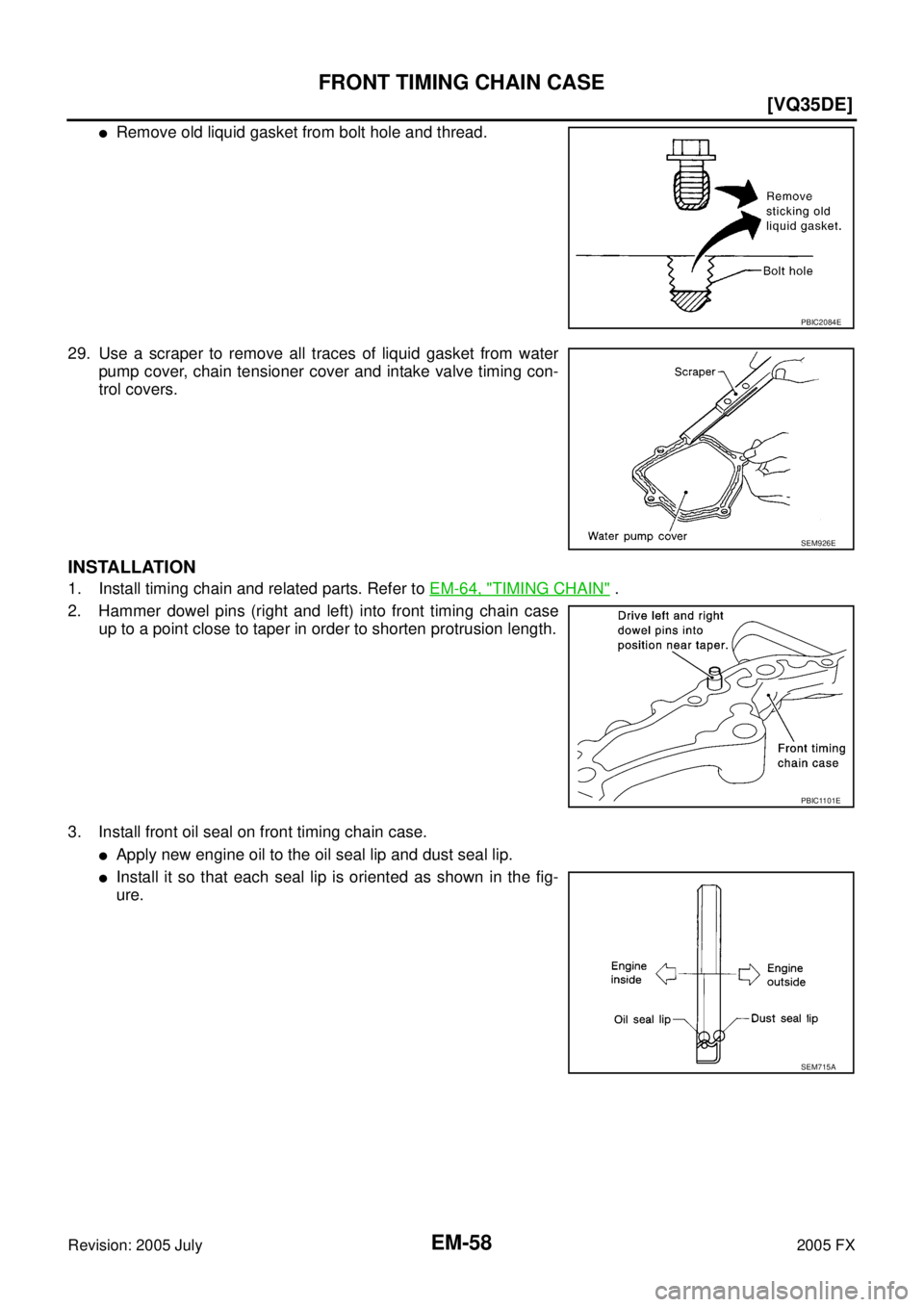
�Remove old liquid gasket from bolt hole and thread.
29. Use a scraper to remove all traces of liquid gasket from water pump cover, chain tensioner cover and intake valve timing con-
trol covers.
INSTALLATION
1. Install timing chain and related parts. Refer to EM-64, "TIMING CHAIN" .
2. Hammer dowel pins (right and left) into front timing chain case up to a point close to taper in order to shorten protrusion length.
3. Install front oil seal on front timing chain case.
�Apply new engine oil to the oil seal lip and dust seal lip.
�Install it so that each seal lip is oriented as shown in the fig-
ure.
PBIC2084E
SEM926E
PBIC1101E
SEM715A
Page 2894 of 4731
FRONT TIMING CHAIN CASE EM-59
[VQ35DE]
C
D E
F
G H
I
J
K L
M A
EM
Revision: 2005 July 2005 FX
�Using a suitable drift [outer diameter: 60 mm (2.36 in)], press-
fit oil seal until it becomes flush with front timing chain case
end face.
�Make sure the garter spring is in position and seal lip is not
inverted.
4. Install water pump cover and chain tensioner cover to front timing chain case.
�Apply a continuous bead of liquid gasket with the tube presser
[SST: WS39930000 ( — )] to front timing chain case as
shown in the figure.
Use Genuine RTV Silicone Sealant or equivalent. Refer to
GI-48, "
RECOMMENDED CHEMICAL PRODUCTS AND
SEALANTS".
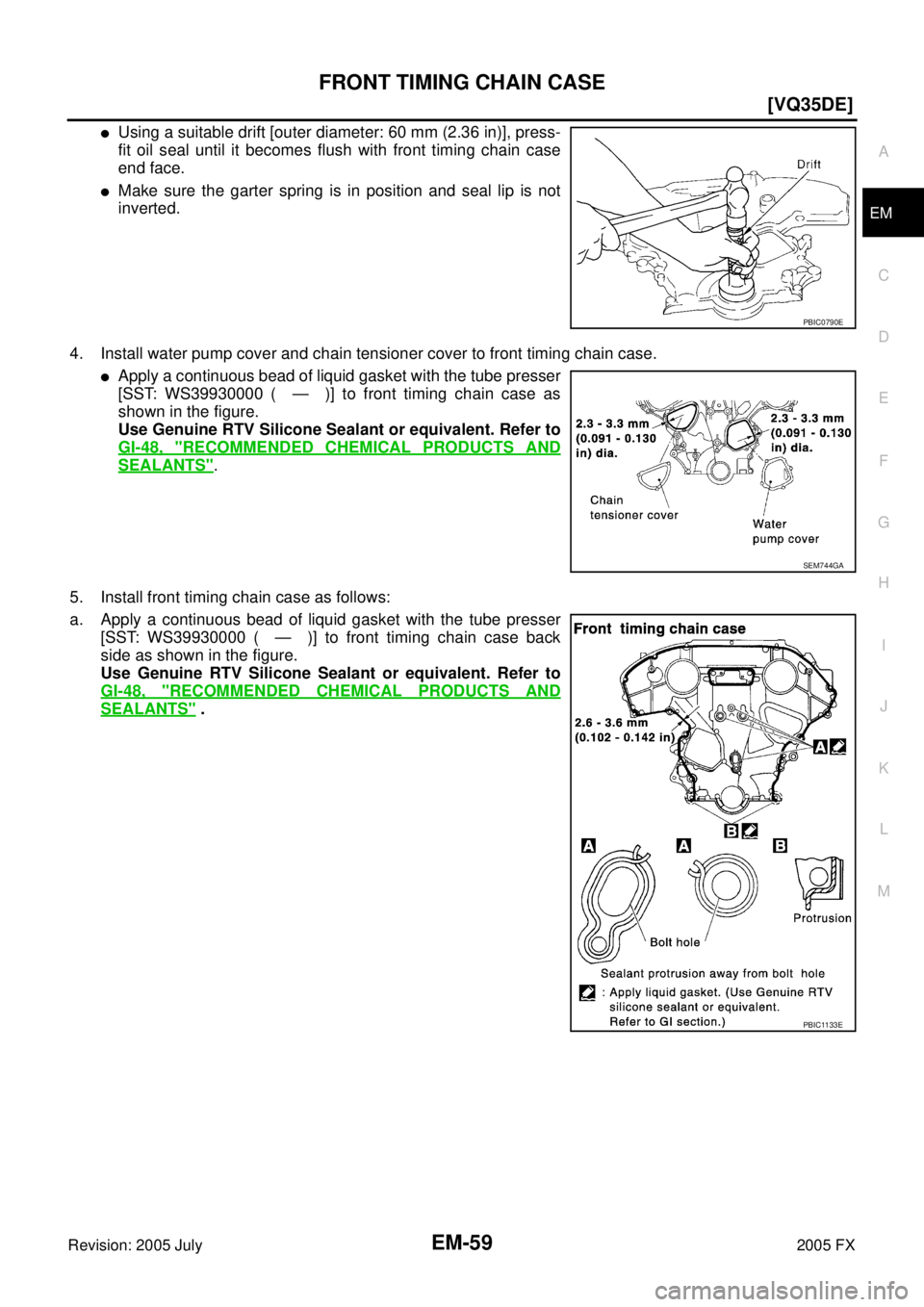
5. Install front timing chain case as follows:
a. Apply a continuous bead of liquid gasket with the tube presser [SST: WS39930000 ( — )] to front timing chain case back
side as shown in the figure.
Use Genuine RTV Silicone Sealant or equivalent. Refer to
GI-48, "
RECOMMENDED CHEMICAL PRODUCTS AND
SEALANTS" .
PBIC0790E
SEM744GA
PBIC1133E
![INFINITI FX35 2005 Service Manual ROCKER COVER EM-53
[VQ35DE]
C
D E
F
G H
I
J
K L
M A
EM
Revision: 2005 July 2005 FX
4. Tighten bolts in two steps separately in numerical order as
shown in the figure.
5. Install oil cat](/manual-img/42/57020/w960_57020-2887.png "INFINITI FX35 2005 Service Manual ROCKER COVER EM-53
[VQ35DE]
C
D E
F
G H
I
J
K L
M A
EM
Revision: 2005 July 2005 FX
4. Tighten bolts in two steps separately in numerical order as
shown in the figure.
5. Install oil cat")
![INFINITI FX35 2005 Service Manual EM-56
[VQ35DE]
FRONT TIMING CHAIN CASE
Revision: 2005 July 2005 FX
b. Loosen crankshaft pulley bolt and locate bolt seating surface as
10 mm (0.39 in) from its original position.
CAUTION:
Do not re](/manual-img/42/57020/w960_57020-2890.png "INFINITI FX35 2005 Service Manual EM-56
[VQ35DE]
FRONT TIMING CHAIN CASE
Revision: 2005 July 2005 FX
b. Loosen crankshaft pulley bolt and locate bolt seating surface as
10 mm (0.39 in) from its original position.
CAUTION:
Do not re")