Page 2872 of 4731
![INFINITI FX35 2005 Service Manual OIL PAN AND OIL STRAINER EM-37
[VQ35DE]
C
D E
F
G H
I
J
K L
M A
EM
Revision: 2005 July 2005 FX
CAUTION:
�Handle carefully to avoid dropping and shocks.
�Do not disassemble.
�Do not allow](/manual-img/42/57020/w960_57020-2871.png "INFINITI FX35 2005 Service Manual OIL PAN AND OIL STRAINER EM-37
[VQ35DE]
C
D E
F
G H
I
J
K L
M A
EM
Revision: 2005 July 2005 FX
CAUTION:
�Handle carefully to avoid dropping and shocks.
�Do not disassemble.
�Do not allow")
OIL PAN AND OIL STRAINER EM-37
[VQ35DE]
C
D E
F
G H
I
J
K L
M A
EM
Revision: 2005 July 2005 FX
CAUTION:
�Handle carefully to avoid dropping and shocks.
�Do not disassemble.
�Do not allow metal powder to adhere to magnetic part at sensor tip.
�Do not place sensors in a location where they are exposed to magnetism.
24. Remove oil pan (lower) as follows:
a. Loosen mounting bolts in reverse order as shown in the figure to remove.
b. Insert the seal cutter [SST] between oil pan (upper) and oil pan (lower).
c. Slide the seal cutter by tapping on the side of tool with a ham- mer. Remove oil pan (lower).
CAUTION:
�Be careful not to damage the mating surface.
�Do not insert flat-bladed screwdriver, this will damage the
mating surface.
25. Remove oil strainer.
26. Remove transmission joint bolts which pierce oil pan (upper). Refer to AT- 2 7 0 , "
TRANSMISSION ASSEM-
BLY" .
27. Loosen mounting bolts in the reverse order as shown in the fig- ure with power tool to remove.
�I n s e r t t h e s e a l c u t t e r [ S S T: K V 1 0 1111 0 0 ( J 3 7 2 2 8 ) ] b e t w e e n o i l
pan (upper) and cylinder block. Slide seal cutter by tapping on
the side of tool with a hammer. Remove oil pan (upper).
CAUTION:
�Be careful not to damage the mating surfaces.
�Do not insert a screwdriver, this will damage the mat-
ing surfaces.
28. Remove O-rings from bottom of cylinder block and oil pump.
PBIC0782E
SEM960F
PBIC0783E
PBIC1144E
Page 2873 of 4731
EM-38
[VQ35DE]
OIL PAN AND OIL STRAINER
Revision: 2005 July 2005 FX
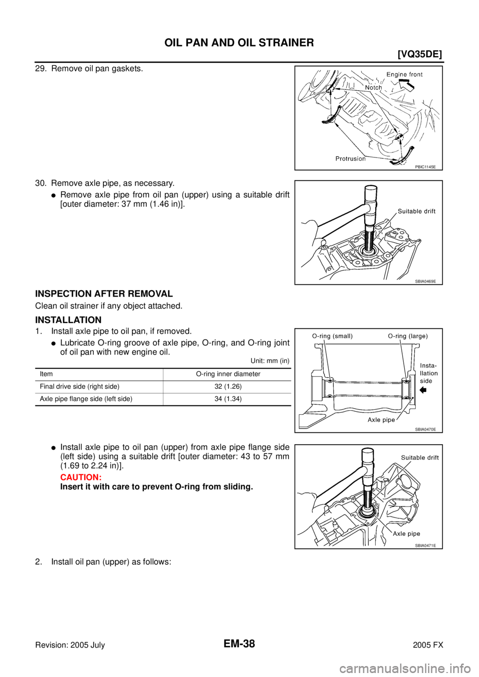
29. Remove oil pan gaskets.
30. Remove axle pipe, as necessary.
�Remove axle pipe from oil pan (upper) using a suitable drift
[outer diameter: 37 mm (1.46 in)].
INSPECTION AFTER REMOVAL
Clean oil strainer if any object attached.
INSTALLATION
1. Install axle pipe to oil pan, if removed.
�Lubricate O-ring groove of axle pipe, O-ring, and O-ring joint
of oil pan with new engine oil.
Unit: mm (in)
�Install axle pipe to oil pan (upper) from axle pipe flange side
(left side) using a suitable drift [outer diameter: 43 to 57 mm
(1.69 to 2.24 in)].
CAUTION:
Insert it with care to prevent O-ring from sliding.
2. Install oil pan (upper) as follows:
PBIC1145E
SBIA0469E
Item O-ring inner diameter
Final drive side (right side) 32 (1.26)
Axle pipe flange side (left side) 34 (1.34)
SBIA0470E
SBIA0471E
Page 2874 of 4731
OIL PAN AND OIL STRAINER EM-39
[VQ35DE]
C
D E
F
G H
I
J
K L
M A
EM
Revision: 2005 July 2005 FX
a. Use a scraper to remove old liquid gasket from mating surfaces.
CAUTION:
Do not scratch or damage the mating surfaces when clean-
ing off old liquid gasket.
�Also remove old liquid gasket from mating surface of cylinder
block.
�Remove old liquid gasket from the bolt holes and threads.
b. Install new oil pan gaskets.
�Apply liquid gasket to oil pan gaskets as shown in the figure.
Use Genuine RTV Silicone Sealant or equivalent. Refer to
GI-48, "
RECOMMENDED CHEMICAL PRODUCTS AND
SEALANTS" .
�To install, align protrusion of oil pan gasket with notches of
front timing chain case and rear oil seal retainer.
�Install oil pan gasket with smaller arc to front timing chain
case side.
c. Install new O-rings on the bottom of cylinder block and oil pump.
MEM108A
PBIC2630E
PBIC1145E
PBIC1144E
Page 2875 of 4731
![INFINITI FX35 2005 Service Manual EM-40
[VQ35DE]
OIL PAN AND OIL STRAINER
Revision: 2005 July 2005 FX
d. Apply a continuous bead of liquid gasket with the tube presser
[SST: WS39930000 ( — )] to the cylinder block mating sur-
face](/manual-img/42/57020/w960_57020-2874.png "INFINITI FX35 2005 Service Manual EM-40
[VQ35DE]
OIL PAN AND OIL STRAINER
Revision: 2005 July 2005 FX
d. Apply a continuous bead of liquid gasket with the tube presser
[SST: WS39930000 ( — )] to the cylinder block mating sur-
face")
EM-40
[VQ35DE]
OIL PAN AND OIL STRAINER
Revision: 2005 July 2005 FX
d. Apply a continuous bead of liquid gasket with the tube presser
[SST: WS39930000 ( — )] to the cylinder block mating sur-
face of oil pan (upper) to a limited portion as shown in the figure.
Use Genuine RTV Silicone Sealant or equivalent. Refer to
GI-48, "
RECOMMENDED CHEMICAL PRODUCTS AND
SEALANTS" .
CAUTION:
�For bolt holes with marks (5 locations), apply liquid
gasket outside the holes.
�Apply a bead of 4.5 to 5.5 mm (0.177 to 0.217 in) in diame-
ter to area “A”.
�Attaching should be done within 5 minutes after coating.
e. Install oil pan (upper). CAUTION:
Install avoiding misalignment of both oil pan gasket and O-rings.
�Tighten mounting bolts in numerical order as shown in the fig-
ure.
�There are two types of mounting bolts. Refer to the following
for locating bolts.
f. Tighten transmission joint bolts. Refer to AT- 2 7 0 , "
TRANSMISSION ASSEMBLY" .
3. Install oil strainer to oil pump.
4. Install oil pan (lower) as follows:
a. Use scraper to remove old liquid gasket from mating surfaces.
�Also remove old liquid gasket from mating surface of oil pan
(upper).
�Remove old liquid gasket from the bolt holes and thread.
CAUTION:
Do not scratch or damage the mating surfaces when clean-
ing off old liquid gasket. M8
× 100 mm (3.94 in) : 5, 7, 8, 11
M8 × 25 mm (0.98 in) : Except the above
PBIC2300E
PBIC0783E
SEM958F
Page 2876 of 4731
![INFINITI FX35 2005 Service Manual OIL PAN AND OIL STRAINER EM-41
[VQ35DE]
C
D E
F
G H
I
J
K L
M A
EM
Revision: 2005 July 2005 FX
b. Apply a continuous bead of liquid gasket with the tube presser
[SST: WS39930000 ( — )]](/manual-img/42/57020/w960_57020-2875.png "INFINITI FX35 2005 Service Manual OIL PAN AND OIL STRAINER EM-41
[VQ35DE]
C
D E
F
G H
I
J
K L
M A
EM
Revision: 2005 July 2005 FX
b. Apply a continuous bead of liquid gasket with the tube presser
[SST: WS39930000 ( — )]")
OIL PAN AND OIL STRAINER EM-41
[VQ35DE]
C
D E
F
G H
I
J
K L
M A
EM
Revision: 2005 July 2005 FX
b. Apply a continuous bead of liquid gasket with the tube presser
[SST: WS39930000 ( — )] to the oil pan (lower) as shown in
the figure.
Use Genuine RTV Silicone Sealant or equivalent. Refer to
GI-48, "
RECOMMENDED CHEMICAL PRODUCTS AND
SEALANTS" .
CAUTION:
Attaching should be done within 5 minutes after coating.
c. Install oil pan (lower).
�Tighten mounting bolts in numerical order as shown in the fig-
ure.
5. Install oil pan drain plug.
�Refer to the figure of components of former page for installation direction of drain plug washer. Refer to
EM-35, "
Components (AWD Model)" .
6. Install in the reverse order of removal after this step.
NOTE:
At least 30 minutes after oil pan is installed, pour engine oil.
INSPECTION AFTER INSTALLATION
1. Check the engine oil level and adjust engine oil. Refer to LU-7, "ENGINE OIL" .
2. Start engine, and check there is no leak of engine oil.
3. Stop engine and wait for 10 minutes.
4. Check the engine oil level again. Refer to LU-7, "
ENGINE OIL" .
PBIC2657E
PBIC0782E
Page 2877 of 4731
EM-42
[VQ35DE]
IGNITION COIL
Revision: 2005 July 2005 FX
IGNITION COILPFP:22448
ComponentsABS00E61
Removal and InstallationABS004U6
REMOVAL
1. Remove engine cover with power tool. Refer to EM-19, "INTAKE MANIFOLD COLLECTOR" .
2. Remove air duct (At the left bank side, remove ignition coil). Refer to EM-17, "
AIR CLEANER AND AIR
DUCT" .
3. Move aside harness, harness bracket, and hoses located above ignition coil.
4. Disconnect harness connector from ignition coil.
5. Remove ignition coil. CAUTION:
Do not shock it.
INSTALLATION
Installation is the reverse order of removal.
1. Ignition coil 2. Spark plug
SBIA0568E
Page 2878 of 4731
![INFINITI FX35 2005 Service Manual SPARK PLUG (PLATINUM-TIPPED TYPE) EM-43
[VQ35DE]
C
D E
F
G H
I
J
K L
M A
EM
Revision: 2005 July 2005 FX
SPARK PLUG (PLATINUM-TIPPED TYPE)PFP:22401
ComponentsABS00E62
Removal and Installat](/manual-img/42/57020/w960_57020-2877.png "INFINITI FX35 2005 Service Manual SPARK PLUG (PLATINUM-TIPPED TYPE) EM-43
[VQ35DE]
C
D E
F
G H
I
J
K L
M A
EM
Revision: 2005 July 2005 FX
SPARK PLUG (PLATINUM-TIPPED TYPE)PFP:22401
ComponentsABS00E62
Removal and Installat")
SPARK PLUG (PLATINUM-TIPPED TYPE) EM-43
[VQ35DE]
C
D E
F
G H
I
J
K L
M A
EM
Revision: 2005 July 2005 FX
SPARK PLUG (PLATINUM-TIPPED TYPE)PFP:22401
ComponentsABS00E62
Removal and InstallationABS004WI
REMOVAL
1. Remove engine cover with power tool. Refer to EM-19, "INTAKE MANIFOLD COLLECTOR" .
2. Remove ignition coil. Refer to EM-42, "
IGNITION COIL" .
3. Remove spark plug with a spark plug wrench (commercial ser- vice tool).
INSPECTION AFTER REMOVAL
Use the standard type spark plug for normal condition.
The hot type spark plug is suitable when fouling occurs with the standard type spark plug under conditions
such as:
�Frequent engine starts
�Low ambient temperatures
The cold type spark plug is suitable when spark knock occurs with the standard type spark plug under condi-
tions such as:
�Extended highway driving
�Frequent high engine revolution
1. Ignition coil 2. Spark plug
SBIA0568E
SEM294A
Make NGK
Standard type PLFR5A-11
Hot type PLFR4A-11
Cold type PLFR6A-11
Gap (Nominal) : 1.1 mm (0.043 in)
Page 2883 of 4731
![INFINITI FX35 2005 Service Manual EM-48
[VQ35DE]
FUEL INJECTOR AND FUEL TUBE
Revision: 2005 July 2005 FX
�Lubricate O-ring with new engine oil.
�Do not clean O-ring with solvent.
�Make sure that O-ring and its mating part are free of](/manual-img/42/57020/w960_57020-2882.png "INFINITI FX35 2005 Service Manual EM-48
[VQ35DE]
FUEL INJECTOR AND FUEL TUBE
Revision: 2005 July 2005 FX
�Lubricate O-ring with new engine oil.
�Do not clean O-ring with solvent.
�Make sure that O-ring and its mating part are free of")
EM-48
[VQ35DE]
FUEL INJECTOR AND FUEL TUBE
Revision: 2005 July 2005 FX
�Lubricate O-ring with new engine oil.
�Do not clean O-ring with solvent.
�Make sure that O-ring and its mating part are free of foreign material.
�When installing O-ring, be careful not to scratch it with tool or fingernails. Also be careful not
to twist or stretch O-ring. If O-ring was stretched while it was being attached, do not insert it
quickly into fuel tube.
�Insert new O-ring straight into fuel tube. Do not decenter or twist it.
�Insert fuel damper and fuel sub-tube straight into fuel tube.
�Tighten mounting bolts evenly in turn.
�After tightening mounting bolts, make sure that there is no gap between flange and fuel tube.
2. Install new O-rings to fuel injector, paying attention to the following.
CAUTION:
�Upper and lower O-ring are different. Be careful not to confuse them.
�Handle O-ring with bare hands. Do not wear gloves.
�Lubricate O-ring with new engine oil.
�Do not clean O-ring with solvent.
�Make sure that O-ring and its mating part are free of foreign material.
�When installing O-ring, be careful not to scratch it with tool or fingernails. Also be careful not to
twist or stretch O-ring. If O-ring was stretched while it was being attached, do not insert it
quickly into fuel tube.
�Insert O-ring straight into fuel injector. Do not decenter or twist it.
3. Install fuel injector to fuel tube as follows:
a. Insert clip into clip mounting groove on fuel injector.
�Insert clip so that protrusion “A” of fuel injector matches cutout
“A” of clip.
CAUTION:
�Do not reuse clip. Replace it with a new one.
�Be careful to keep clip from interfering with O-ring. If
interference occurs, replace O-ring.
b. Insert fuel injector into fuel tube with clip attached.
�Insert it while matching it to the axial center.
�Insert fuel injector so that protrusion “B” of fuel tube matches
cutout “B” of clip.
�Make sure that fuel tube flange is securely fixed in flange fix-
ing groove on clip.
c. Make sure that installation is complete by checking that fuel injector does not rotate or come off.
�Make sure that protrusions of fuel injectors are aligned with
cutouts of clips after installation.
4. Install spacers on intake manifold.
5. Install fuel tube and fuel injector assembly to intake manifold. CAUTION:
Be careful not to let tip of injector nozzle come in contact with other parts. Fuel tube side : Blue
Nozzle side : Brown
PBIC2545E
![INFINITI FX35 2005 Service Manual OIL PAN AND OIL STRAINER EM-39
[VQ35DE]
C
D E
F
G H
I
J
K L
M A
EM
Revision: 2005 July 2005 FX
a. Use a scraper to remove old liquid gasket from mating surfaces.
CAUTION:
Do not scratch](/manual-img/42/57020/w960_57020-2873.png "INFINITI FX35 2005 Service Manual OIL PAN AND OIL STRAINER EM-39
[VQ35DE]
C
D E
F
G H
I
J
K L
M A
EM
Revision: 2005 July 2005 FX
a. Use a scraper to remove old liquid gasket from mating surfaces.
CAUTION:
Do not scratch")
![INFINITI FX35 2005 Service Manual EM-42
[VQ35DE]
IGNITION COIL
Revision: 2005 July 2005 FX
IGNITION COILPFP:22448
ComponentsABS00E61
Removal and InstallationABS004U6
REMOVAL
1. Remove engine cover with power tool. Refer to EM-19, "INT](/manual-img/42/57020/w960_57020-2876.png "INFINITI FX35 2005 Service Manual EM-42
[VQ35DE]
IGNITION COIL
Revision: 2005 July 2005 FX
IGNITION COILPFP:22448
ComponentsABS00E61
Removal and InstallationABS004U6
REMOVAL
1. Remove engine cover with power tool. Refer to EM-19, \"INT")