Page 2721 of 4731
![INFINITI FX35 2005 Service Manual EC-1328
[VK45DE]
DTC P2138 APP SENSOR
Revision: 2005 July 2005 FX
5. CHECK APP SENSOR 2 POWER SUPPLY CIRCUIT-II
1. Turn ignition switch OFF.
2. Disconnect ECM harness connector.
3. Check harness con](/manual-img/42/57020/w960_57020-2720.png "INFINITI FX35 2005 Service Manual EC-1328
[VK45DE]
DTC P2138 APP SENSOR
Revision: 2005 July 2005 FX
5. CHECK APP SENSOR 2 POWER SUPPLY CIRCUIT-II
1. Turn ignition switch OFF.
2. Disconnect ECM harness connector.
3. Check harness con")
EC-1328
[VK45DE]
DTC P2138 APP SENSOR
Revision: 2005 July 2005 FX
5. CHECK APP SENSOR 2 POWER SUPPLY CIRCUIT-II
1. Turn ignition switch OFF.
2. Disconnect ECM harness connector.
3. Check harness continuity between APP sensor terminal 4 and ECM terminal 91. Refer to Wiring Diagram.
OK or NG
OK >> GO TO 7.
NG >> GO TO 6.
6. DETECT MALFUNCTIONING PART
Check the following.
�Harness connectors E211, M41
�Harness for open or short between ECM and accelerator pedal position sensor
>> Repair open circuit.
7. CHECK APP SENSOR 2 POWER SUPPLY CIRCUIT-III
Check harness for short to power and short to ground, between the following terminals.
OK or NG
OK >> GO TO 8.
NG >> Repair short to ground or short to power in harness or connectors.
8. CHECK THROTTLE POSITION SENSOR
Refer to EC-1322, "
Component Inspection" .
OK or NG
OK >> GO TO 16.
NG >> GO TO 9.
9. REPLACE ELECTRIC THROTTLE CONTROL ACTUATOR
1. Replace the electric throttle control actuator.
2. Perform EC-786, "
Throttle Valve Closed Position Learning" .
3. Perform EC-787, "
Idle Air Volume Learning" .
>> INSPECTION END
Continuity should exist.
ECM terminal Sensor terminal Reference Wiring Diagram
91 APP sensor terminal 4 EC-1325
47 Electric throttle control actuator terminal 1EC-1318
Page 2723 of 4731
![INFINITI FX35 2005 Service Manual EC-1330
[VK45DE]
DTC P2138 APP SENSOR
Revision: 2005 July 2005 FX
15. REPLACE ACCELERATOR PEDAL ASSEMBLY
1. Replace accelerator pedal assembly.
2. Perform EC-786, "
Accelerator Pedal Released Posi](/manual-img/42/57020/w960_57020-2722.png "INFINITI FX35 2005 Service Manual EC-1330
[VK45DE]
DTC P2138 APP SENSOR
Revision: 2005 July 2005 FX
15. REPLACE ACCELERATOR PEDAL ASSEMBLY
1. Replace accelerator pedal assembly.
2. Perform EC-786, \"
Accelerator Pedal Released Posi")
EC-1330
[VK45DE]
DTC P2138 APP SENSOR
Revision: 2005 July 2005 FX
15. REPLACE ACCELERATOR PEDAL ASSEMBLY
1. Replace accelerator pedal assembly.
2. Perform EC-786, "
Accelerator Pedal Released Position Learning" .
3. Perform EC-786, "
Throttle Valve Closed Position Learning" .
4. Perform EC-787, "
Idle Air Volume Learning" .
>> INSPECTION END
16. CHECK INTERMITTENT INCIDENT
Refer to EC-854, "
TROUBLE DIAGNOSIS FOR INTERMITTENT INCIDENT" .
>> INSPECTION END
Component InspectionABS007WI
ACCELERATOR PEDAL POSITION SENSOR
1. Reconnect all harness connectors disconnected.
2. Turn ignition switch ON.
3. Check voltage between ECM terminals 106 (APP sensor 1 sig- nal), 98 (APP sensor 2 signal) and ground under the following
conditions.
4. If NG, replace accelerator pedal assembly and go to next step.
5. Perform EC-786, "
Accelerator Pedal Released Position Learning" .
6. Perform EC-786, "
Throttle Valve Closed Position Learning" .
7. Perform EC-787, "
Idle Air Volume Learning" .
Removal and InstallationABS007WJ
ACCELERATOR PEDAL
Refer to ACC-3, "ACCELERATOR CONTROL SYSTEM" .
Terminal Accelerator pedal Voltage
106
(Accelerator pedal position
sensor 1) Fully released 0.5 - 1.0V
Fully depressed 3.9 - 4.7V
98
(Accelerator pedal position
sensor 2) Fully released 0.15 - 0.60V
Fully depressed 1.95 - 2.40V
MBIB0023E
Page 2724 of 4731
![INFINITI FX35 2005 Service Manual VARIABLE INDUCTION AIR CONTROL SYSTEM (VIAS) EC-1331
[VK45DE]
C
D E
F
G H
I
J
K L
M A
EC
Revision: 2005 July 2005 FX
VARIABLE INDUCTION AIR CONTROL SYSTEM (VIAS)PFP:14956
DescriptionABS00](/manual-img/42/57020/w960_57020-2723.png "INFINITI FX35 2005 Service Manual VARIABLE INDUCTION AIR CONTROL SYSTEM (VIAS) EC-1331
[VK45DE]
C
D E
F
G H
I
J
K L
M A
EC
Revision: 2005 July 2005 FX
VARIABLE INDUCTION AIR CONTROL SYSTEM (VIAS)PFP:14956
DescriptionABS00")
VARIABLE INDUCTION AIR CONTROL SYSTEM (VIAS) EC-1331
[VK45DE]
C
D E
F
G H
I
J
K L
M A
EC
Revision: 2005 July 2005 FX
VARIABLE INDUCTION AIR CONTROL SYSTEM (VIAS)PFP:14956
DescriptionABS007WK
SYSTEM DESCRIPTION
*: The ECM determines the start signal status by the signals of engine speed and battery voltage.
When the engine is running at low or medium speed, the power valve is fully closed. Under this condition, the
effective suction port length is equivalent to the total length of the intake manifold collector's suction port
including the intake valve. This long suction port provides increased air intake which results in improved suc-
tion efficiency and higher torque generation.
The surge tank and one-way valve are provided. When engine is running at high speed, the ECM sends the
signal to the VIAS control solenoid valve. This signal introduces the intake manifold vacuum into the power
valve actuator and therefore opens the power valve to two suction passages together in the collector.
Under this condition, the effective port length is equivalent to the length of the suction port provided indepen-
dently for each cylinder. This shortened port length results in enhanced engine output with reduced suction
resistance under high speeds.
The power valve is always open regardless of the engine speed when gear position is in N or P.
Sensor Input signal to ECM ECM function Actuator
Crankshaft position sensor (POS)
Camshaft position sensor (PHASE) Engine speed*
VIAS control VIAS control solenoid valve
Mass air flow sensor Amount of intake air
Throttle position sensor Throttle position
Accelerator pedal position sensor Accelerator pedal position
Battery Battery voltage*
Engine coolant temperature sensor Engine coolant temperature
PBIB1876E
Page 2854 of 4731
INTAKE MANIFOLD COLLECTOR EM-19
[VQ35DE]
C
D E
F
G H
I
J
K L
M A
EM
Revision: 2005 July 2005 FX
INTAKE MANIFOLD COLLECTORPFP:14003
ComponentsABS00E5W
Removal and InstallationABS009RG
REMOVAL
WARNING:
�To avoid the danger of being scalded, never drain engine coolant when the engine is hot.
�Gasket for intake manifold collector (upper) is secured together with mounting bolt for intake man-
ifold collector (lower). Thus, even when only gasket for upper side is replaced, gasket for lower
side must be also replaced.
1. Electric throttle control actuator 2. Gasket 3. Vacuum hose
4. EVAP canister purge volume control
solenoid valve 5. Bracket 6. Intake manifold collector (upper)
7. Intake manifold collector cover 8. Gasket 9. Water hose
10. Bracket 11. Water hose 12. PCV hose
13. Intake manifold collector (lower)
SBIA0585E
Page 2855 of 4731
![INFINITI FX35 2005 Service Manual EM-20
[VQ35DE]
INTAKE MANIFOLD COLLECTOR
Revision: 2005 July 2005 FX
1. Remove engine cover with power tool.
2. Disconnect water hoses from intake manifold collector (upper), attach blind plug to pre](/manual-img/42/57020/w960_57020-2854.png "INFINITI FX35 2005 Service Manual EM-20
[VQ35DE]
INTAKE MANIFOLD COLLECTOR
Revision: 2005 July 2005 FX
1. Remove engine cover with power tool.
2. Disconnect water hoses from intake manifold collector (upper), attach blind plug to pre")
EM-20
[VQ35DE]
INTAKE MANIFOLD COLLECTOR
Revision: 2005 July 2005 FX
1. Remove engine cover with power tool.
2. Disconnect water hoses from intake manifold collector (upper), attach blind plug to prevent engine coolant leakage.
CAUTION:
�Perform this step when the engine is cold.
�Do not spill engine coolant on drive belts.
3. Remove air cleaner case and air duct. Refer to EM-17, "
AIR CLEANER AND AIR DUCT" .
4. Remove electric throttle control actuator as the following:
a. Disconnect harness connector.
b. Loosen mounting bolts in reverse order as shown in the figure. CAUTION:
�Handle carefully to avoid any shock to electric throttle
control actuator.
�Do not disassemble.
5. Remove fuel sub-tube mounting bolt to disconnect from rear of intake manifold collector (lower). Refer to EM-45, "
FUEL INJECTOR AND FUEL TUBE" .
6. Disconnect vacuum hose and water hose from intake manifold collector (upper).
7. Remove EVAP canister purge volume control solenoid valve bracket mounting bolt from intake manifold collector (upper).
SBIA0486E
KBIA0957E
Page 2858 of 4731
INTAKE MANIFOLD COLLECTOR EM-23
[VQ35DE]
C
D E
F
G H
I
J
K L
M A
EM
Revision: 2005 July 2005 FX
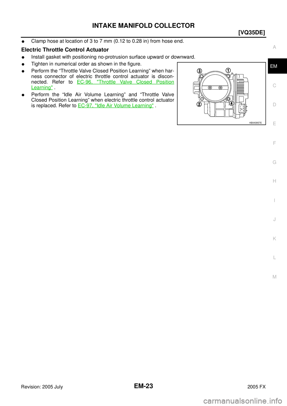
�Clamp hose at location of 3 to 7 mm (0.12 to 0.28 in) from hose end.
Electric Throttle Control Actuator
�Install gasket with positioning no-protrusion surface upward or downward.
�Tighten in numerical order as shown in the figure.
�Perform the “Throttle Valve Closed Position Learning” when har-
ness connector of electric throttle control actuator is discon-
nected. Refer to EC-96, "
Throttle Valve Closed Position
Learning" .
�Perform the “Idle Air Volume Learning” and “Throttle Valve
Closed Position Learning” when electric throttle control actuator
is replaced. Refer to EC-97, "
Idle Air Volume Learning" .
KBIA0957E
Page 2871 of 4731
![INFINITI FX35 2005 Service Manual EM-36
[VQ35DE]
OIL PAN AND OIL STRAINER
Revision: 2005 July 2005 FX
Removal and Installation (AWD Model)ABS00E3Q
REMOVAL
CAUTION:
To avoid the danger of being scalded, never drain engine oil when the](/manual-img/42/57020/w960_57020-2870.png "INFINITI FX35 2005 Service Manual EM-36
[VQ35DE]
OIL PAN AND OIL STRAINER
Revision: 2005 July 2005 FX
Removal and Installation (AWD Model)ABS00E3Q
REMOVAL
CAUTION:
To avoid the danger of being scalded, never drain engine oil when the")
EM-36
[VQ35DE]
OIL PAN AND OIL STRAINER
Revision: 2005 July 2005 FX
Removal and Installation (AWD Model)ABS00E3Q
REMOVAL
CAUTION:
To avoid the danger of being scalded, never drain engine oil when the engine is hot.
NOTE:
To remove oil pan (lower) only, take step 5, then step 24. Removal of step 1, hood assembly (step 2) and step
4 are unnecessary.
1. Remove front tire.
2. Remove hood assembly. Refer to BL-13, "
HOOD" .
3. Remove front and rear engine undercover with power tool.
4. Remove front cross bar with power tool. Refer to FSU-6, "
FRONT SUSPENSION ASSEMBLY" .
5. Drain engine oil. Refer to LU-9, "
Changing Engine Oil" .
CAUTION:
�Perform this step when the engine is cold.
�Do not spill engine oil on drive belts.
6. Drain engine coolant. Refer to CO-11, "
Changing Engine Coolant" .
CAUTION:
�Perform this step when the engine is cold.
�Do not spill engine coolant on drive belts.
7. Remove engine cover with power tool. Refer to EM-19, "
INTAKE MANIFOLD COLLECTOR" .
8. Remove air hose from air duct to mass air flow sensor side and electric throttle control actuator side. Refer to EM-17, "
AIR CLEANER AND AIR DUCT" .
9. Remove drive belts. Refer to EM-15, "
DRIVE BELTS" .
10. Remove front drive shaft (LH and RH) and side shaft. Refer to FAX-12, "
FRONT DRIVE SHAFT" .
11. Remove side shaft. Refer to FFD-12, "
FRONT FINAL DRIVE ASSEMBLY" .
12. Removal engine rear lower slinger, and install engine rear slinger [SST: 10006 31U00 ( — )] to sling engine assembly for positioning. Refer to EM-8, "
Special Service Tools" .
13. Remove front suspension member. Refer to Refer to FSU-17, "
FRONT SUSPENSION MEMBER" .
14. Remove engine mounting bracket, engine mounting bracket (lower) and insulator. Refer to EM-112,
"ENGINE ASSEMBLY" .
15. Remove front propeller shaft. Refer to PR-4, "
FRONT PROPELLER SHAFT" .
16. Remove oil filter and oil filter bracket. Refer to LU-12, "
OIL FILTER BRACKET (AWD)" .
17. Remove alternator stay. Refer to SC-23, "
CHARGING SYSTEM" .
18. Remove idler pulley and bracket. Refer to EM-15, "
DRIVE BELTS" .
19. Disconnect oil cooler water hoses, and remove oil cooler water pipe mounting bolt. Refer to LU-14, "
OIL
COOLER" .
20. Disconnect A/T fluid cooler hoses, and remove A/T fluid cooler tube. Refer to AT- 2 7 0 , "
TRANSMISSION
ASSEMBLY" .
21. Remove front final drive assembly. Refer to FFD-12, "
FRONT FINAL DRIVE ASSEMBLY" .
22. Remove starter motor. Refer to SC-10, "
STARTING SYSTEM" .
23. Remove crankshaft position sensor (POS).
1. Oil pan gasket (rear) 2. Oil pan (upper) 3. O-ring
4. Oil pan gasket (front) 5. Oil filter 6. Connector bolt
7. Oil cooler 8. O-ring 9. Relief valve
10. Oil filter bracket 11. Oil filter bracket gasket 12. Oil strainer
13. Drain plug 14. Drain plug washer 15. Oil pan (lower)
16. Rear plate 17. Crankshaft position sensor (POS) 18 O-ring (small)
19. O-ring (large) 20. Axle pipe
Slinger bolts: : 28.0 N·m (2.9 kg-m, 21 ft-lb)
Page 3013 of 4731
EM-178
[VK45DE]
INTAKE MANIFOLD
Revision: 2005 July 2005 FX
INTAKE MANIFOLDPFP:14003
ComponentsABS00DFO
1. PCV tube 2. Engine cover rear bracket 3. EVAP canister purge control sole-
noid valve
4. EVAP hose 5. EVAP tube 6. EVAP hose
7. Vacuum gallery 8. Engine cover front bracket 9. Vacuum tank
10. VIAS control solenoid valve 11. Water gallery 12. Gasket
13. Intake manifold (lower) 14. Gasket 15. Water hose
16. Intake manifold adapter 17. Electric throttle control actuator 18. Gasket
19. Intake manifold (upper) 20. Resonator 21. EVAP service port
PBIC2755E
![INFINITI FX35 2005 Service Manual INTAKE MANIFOLD COLLECTOR EM-19
[VQ35DE]
C
D E
F
G H
I
J
K L
M A
EM
Revision: 2005 July 2005 FX
INTAKE MANIFOLD COLLECTORPFP:14003
ComponentsABS00E5W
Removal and InstallationABS009RG
REMO](/manual-img/42/57020/w960_57020-2853.png "INFINITI FX35 2005 Service Manual INTAKE MANIFOLD COLLECTOR EM-19
[VQ35DE]
C
D E
F
G H
I
J
K L
M A
EM
Revision: 2005 July 2005 FX
INTAKE MANIFOLD COLLECTORPFP:14003
ComponentsABS00E5W
Removal and InstallationABS009RG
REMO")
![INFINITI FX35 2005 Service Manual EM-178
[VK45DE]
INTAKE MANIFOLD
Revision: 2005 July 2005 FX
INTAKE MANIFOLDPFP:14003
ComponentsABS00DFO
1. PCV tube 2. Engine cover rear bracket 3. EVAP canister purge control sole-
noid valve
4. EV](/manual-img/42/57020/w960_57020-3012.png "INFINITI FX35 2005 Service Manual EM-178
[VK45DE]
INTAKE MANIFOLD
Revision: 2005 July 2005 FX
INTAKE MANIFOLDPFP:14003
ComponentsABS00DFO
1. PCV tube 2. Engine cover rear bracket 3. EVAP canister purge control sole-
noid valve
4. EV")