2005 INFINITI FX35 Ignition switch
[x] Cancel search: Ignition switchPage 4529 of 4731
SE-56
AUTOMATIC DRIVE POSITIONER
Revision: 2005 July 2005 FX
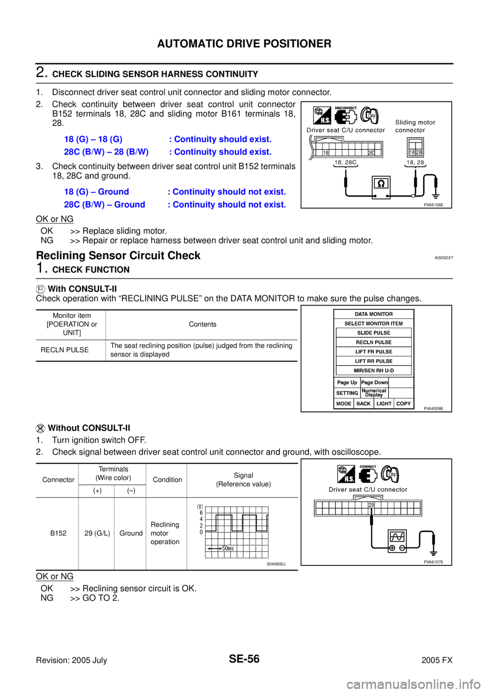
2. CHECK SLIDING SENSOR HARNESS CONTINUITY
1. Disconnect driver seat control unit connector and sliding motor connector.
2. Check continuity between driver seat control unit connector B152 terminals 18, 28C and sliding motor B161 terminals 18,
28.
3. Check continuity between driver seat control unit B152 terminals 18, 28C and ground.
OK or NG
OK >> Replace sliding motor.
NG >> Repair or replace harness between driver seat control unit and sliding motor.
Reclining Sensor Circuit CheckAIS002XT
1. CHECK FUNCTION
With CONSULT-II
Check operation with “RECLINING PULSE” on the DATA MONITOR to make sure the pulse changes.
Without CONSULT-II
1. Turn ignition switch OFF.
2. Check signal between driver seat control unit connector and ground, with oscilloscope.
OK or NG
OK >> Reclining sensor circuit is OK.
NG >> GO TO 2. 18 (G) – 18 (G) : Continuity should exist.
28C (B/W) – 28 (B/W) : Continuity should exist.
18 (G) – Ground : Continuity should not exist.
28C (B/W) – Ground : Continuity should not exist.
PIIA6106E
Monitor item
[POERATION or UNIT] Contents
RECLN PULSE The seat reclining position (pulse) judged from the reclining
sensor is displayed
PIIA4558E
Connector Te r m i n a l s
(Wire color) Condition Signal
(Reference value)
(+) (–)
B152 29 (G/L) Ground Reclining
motor
operation
PIIA6107ESIIA0692J
Page 4530 of 4731
AUTOMATIC DRIVE POSITIONER SE-57
C
D E
F
G H
J
K L
M A
B
SE
Revision: 2005 July 2005 FX
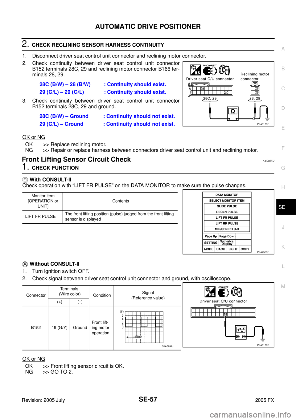
2. CHECK RECLINING SENSOR HARNESS CONTINUITY
1. Disconnect driver seat control unit connector and reclining motor connector.
2. Check continuity between driver seat control unit connector B152 terminals 28C, 29 and reclining motor connector B166 ter-
minals 28, 29.
3. Check continuity between driver seat control unit connector B152 terminals 28C, 29 and ground.
OK or NG
OK >> Replace reclining motor.
NG >> Repair or replace harness between connectors driver seat control unit and reclining motor.
Front Lifting Sensor Circuit CheckAIS002XU
1. CHECK FUNCTION
With CONSULT-II
Check operation with “LIFT FR PULSE” on the DATA MONITOR to make sure the pulse changes.
Without CONSULT-II
1. Turn ignition switch OFF.
2. Check signal between driver seat control unit connector and ground, with oscilloscope.
OK or NG
OK >> Front lifting sensor circuit is OK.
NG >> GO TO 2. 28C (B/W) – 28 (B/W) : Continuity should exist.
29 (G/L) – 29 (G/L) : Continuity should exist.
28C (B/W) – Ground : Continuity should not exist.
29 (G/L) – Ground : Continuity should not exist.
PIIA6108E
Monitor item
[OPERATION or UNIT] Contents
LIFT FR PULSE The front lifting position (pulse) judged from the front lifting
sensor is displayed
PIIA4558E
Connector Terminals
(Wire color) Condition Signal
(Reference value)
(+) (–)
B152 19 (G/Y) Ground Front lift-
ing motor
operation
PIIA6109ESIIA0691J
Page 4531 of 4731
SE-58
AUTOMATIC DRIVE POSITIONER
Revision: 2005 July 2005 FX
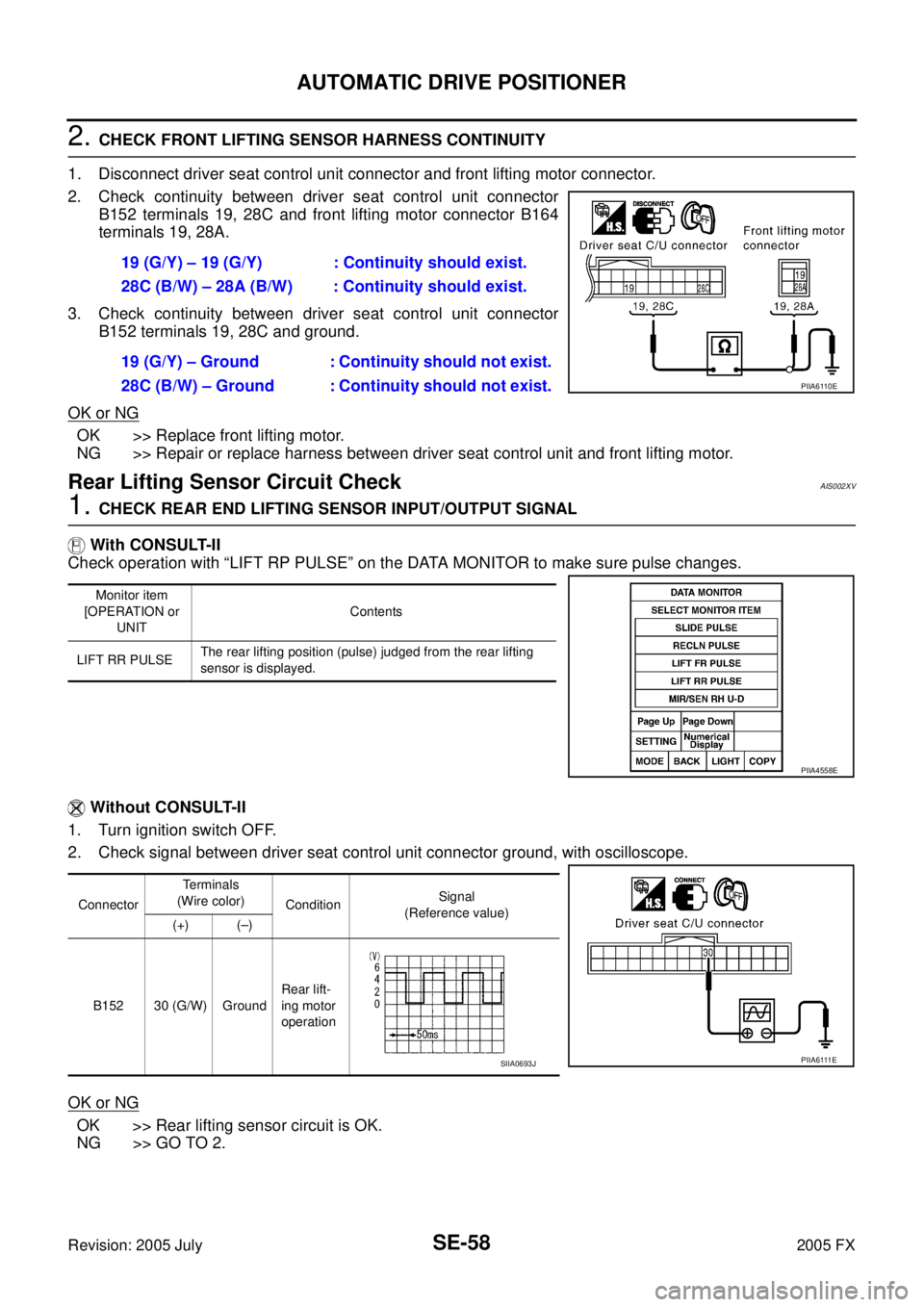
2. CHECK FRONT LIFTING SENSOR HARNESS CONTINUITY
1. Disconnect driver seat control unit connector and front lifting motor connector.
2. Check continuity between driver seat control unit connector B152 terminals 19, 28C and front lifting motor connector B164
terminals 19, 28A.
3. Check continuity between driver seat control unit connector B152 terminals 19, 28C and ground.
OK or NG
OK >> Replace front lifting motor.
NG >> Repair or replace harness between driver seat control unit and front lifting motor.
Rear Lifting Sensor Circuit CheckAIS002XV
1. CHECK REAR END LIFTING SENSOR INPUT/OUTPUT SIGNAL
With CONSULT-II
Check operation with “LIFT RP PULSE” on the DATA MONITOR to make sure pulse changes.
Without CONSULT-II
1. Turn ignition switch OFF.
2. Check signal between driver seat control unit connector ground, with oscilloscope.
OK or NG
OK >> Rear lifting sensor circuit is OK.
NG >> GO TO 2. 19 (G/Y) – 19 (G/Y) : Continuity should exist.
28C (B/W) – 28A (B/W) : Continuity should exist.
19 (G/Y) – Ground : Continuity should not exist.
28C (B/W) – Ground : Continuity should not exist.
PIIA6110E
Monitor item
[OPERATION or UNIT Contents
LIFT RR PULSE The rear lifting position (pulse) judged from the rear lifting
sensor is displayed.
PIIA4558E
Connector Te r m i n a l s
(Wire color) Condition Signal
(Reference value)
(+) (–)
B152 30 (G/W) Ground Rear lift-
ing motor
operation
P I I A 6 111 ESIIA0693J
Page 4532 of 4731
AUTOMATIC DRIVE POSITIONER SE-59
C
D E
F
G H
J
K L
M A
B
SE
Revision: 2005 July 2005 FX
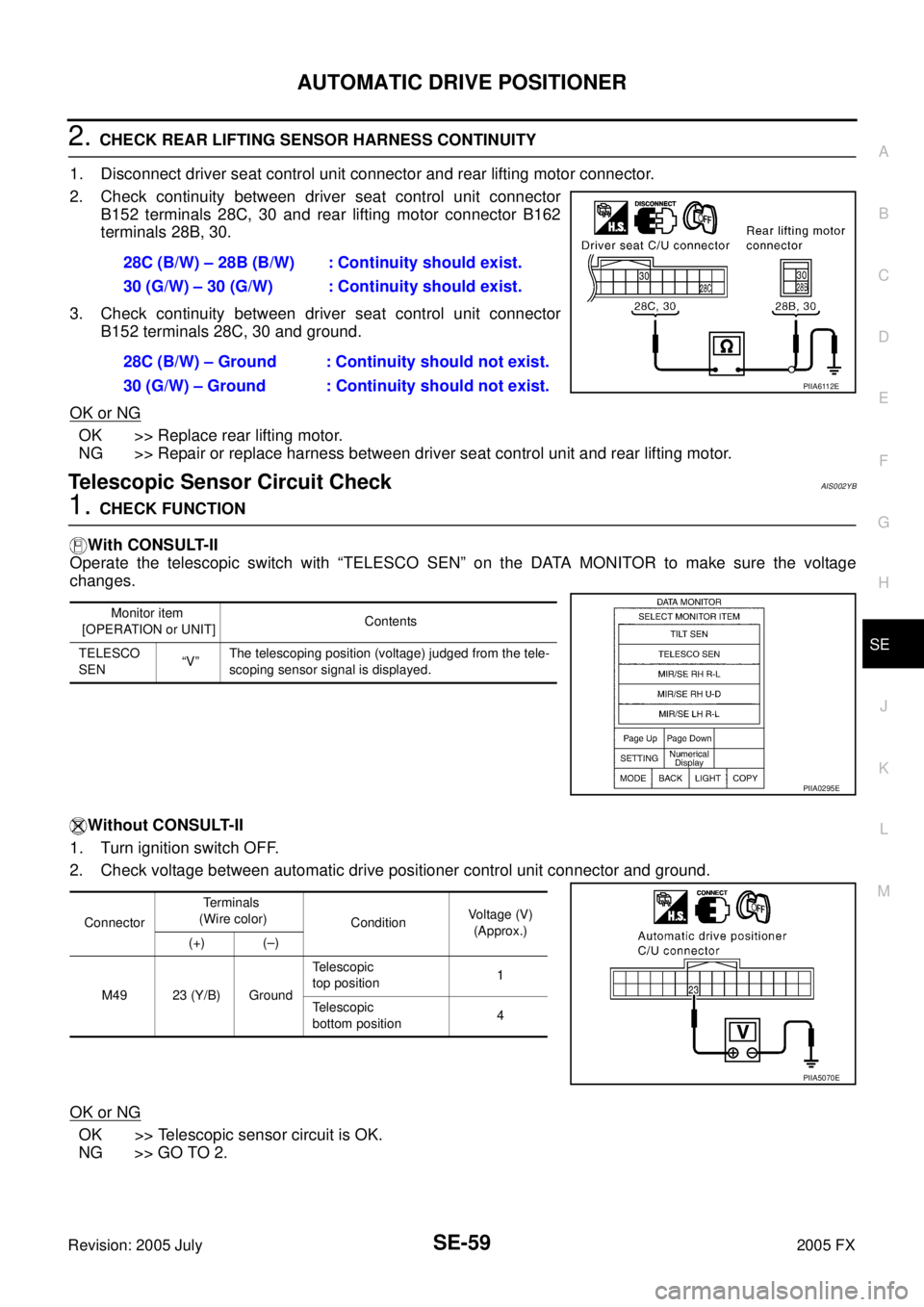
2. CHECK REAR LIFTING SENSOR HARNESS CONTINUITY
1. Disconnect driver seat control unit connector and rear lifting motor connector.
2. Check continuity between driver seat control unit connector B152 terminals 28C, 30 and rear lifting motor connector B162
terminals 28B, 30.
3. Check continuity between driver seat control unit connector B152 terminals 28C, 30 and ground.
OK or NG
OK >> Replace rear lifting motor.
NG >> Repair or replace harness between driver seat control unit and rear lifting motor.
Telescopic Sensor Circuit CheckAIS002YB
1. CHECK FUNCTION
With CONSULT-II
Operate the telescopic switch with “TELESCO SEN” on the DATA MONITOR to make sure the voltage
changes.
Without CONSULT-II
1. Turn ignition switch OFF.
2. Check voltage between automatic drive positioner control unit connector and ground.
OK or NG
OK >> Telescopic sensor circuit is OK.
NG >> GO TO 2. 28C (B/W) – 28B (B/W) : Continuity should exist.
30 (G/W) – 30 (G/W) : Continuity should exist.
28C (B/W) – Ground : Continuity should not exist.
30 (G/W) – Ground : Continuity should not exist.
PIIA6112E
Monitor item
[OPERATION or UNIT] Contents
TELESCO
SEN “V” The telescoping position (voltage) judged from the tele-
scoping sensor signal is displayed.
PIIA0295E
Connector Terminals
(Wire color) Condition Voltage (V)
(Approx.)
(+) (–)
M49 23 (Y/B) Ground Telescopic
top position 1
Telescopic
bottom position 4
PIIA5070E
Page 4533 of 4731
SE-60
AUTOMATIC DRIVE POSITIONER
Revision: 2005 July 2005 FX
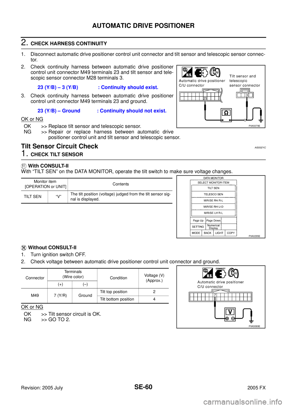
2. CHECK HARNESS CONTINUITY
1. Disconnect automatic drive positioner control unit connector and tilt sensor and telescopic sensor connec- tor.
2. Check continuity harness between automatic drive positioner control unit connector M49 terminals 23 and tilt sensor and tele-
scopic sensor connector M28 terminals 3.
3. Check continuity harness between automatic drive positioner control unit connector M49 terminals 23 and ground.
OK or NG
OK >> Replace tilt sensor and telescopic sensor.
NG >> Repair or replace harness between automatic drive positioner control unit and tilt sensor and telescopic sensor.
Tilt Sensor Circuit CheckAIS002YC
1. CHECK TILT SENSOR
With CONSULT-II
With “TILT SEN” on the DATA MONITOR, operate the tilt switch to make sure voltage changes.
Without CONSULT-II
1. Turn ignition switch OFF.
2. Check voltage between automatic drive positioner control unit connector and ground.
OK or NG
OK >> Tilt sensor circuit is OK.
NG >> GO TO 2. 23 (Y/B) – 3 (Y/B) : Continuity should exist.
23 (Y/B) – Ground : Continuity should not exist.
PIIA5079E
Monitor item
[OPERATION or UNIT] Contents
TILT SEN “V” The tilt position (voltage) judged from the tilt sensor sig-
nal is displayed.
PIIA0295E
Connector Terminals
(Wire color) Condition Voltage (V)
(Approx.)
(+) (–)
M49 7 (Y/R) Ground Tilt top position 2
Tilt bottom position 4
PIIA5069E
Page 4535 of 4731
SE-62
AUTOMATIC DRIVE POSITIONER
Revision: 2005 July 2005 FX
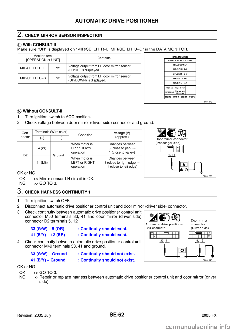
2. CHECK MIRROR SENSOR INSPECTION
With CONSULT-II
Make sure “ON” is displayed on “MIR/SE LH R–L, MIR/SE LH U–D” in the DATA MONITOR.
Without CONSULT-II
1. Turn ignition switch to ACC position.
2. Check voltage between door mirror (driver side) connector and ground.
OK or NG
OK >> Mirror sensor LH circuit is OK.
NG >> GO TO 3.
3. CHECK HARNESS CONTINUITY 1
1. Turn ignition switch OFF.
2. Disconnect automatic drive positioner control unit and door mirror (driver side) connector.
3. Check continuity between automatic drive positioner control unit connector M50 terminals 33, 41 and door mirror (driver side)
connector D2 terminals 5, 12.
4. Check continuity between automatic drive positioner control unit connector M49 terminals 33, 41 and ground.
OK or NG
OK >> GO TO 3.
NG >> Repair or replace harness between automatic drive positioner control unit and door mirror (driver side).
Monitor item
[OPERATION or UNIT] Contents
MIR/SE LH R–L “V” Voltage output from LH door mirror sensor
(LH/RH) is displayed.
MIR/SE LH U–D “V” Voltage output from LH door mirror sensor
(UP/DOWN) is displayed.
PIIA0197E
Con-
nector Terminals (Wire color)
Condition Voltage (V)
(Approx,)
(+) (–)
D2 4 (W)
Ground When motor is
UP or DOWN
operation Changes between
3 (close to perk) –
1 (close to valley)
11 (LG) When motor is
LEFT or RIGHT
operation Changes between
3 (close to right edge) – 1 (close to left edge)
PIIA6126E
33 (G/W) – 5 (OR) : Continuity should exist.
41 (B/Y) – 12 (BR) : Continuity should exist.
33 (G/W) – Ground : Continuity should not exist.
41 (B/Y) – Ground : Continuity should not exist.
PIIA6134E
Page 4537 of 4731
SE-64
AUTOMATIC DRIVE POSITIONER
Revision: 2005 July 2005 FX
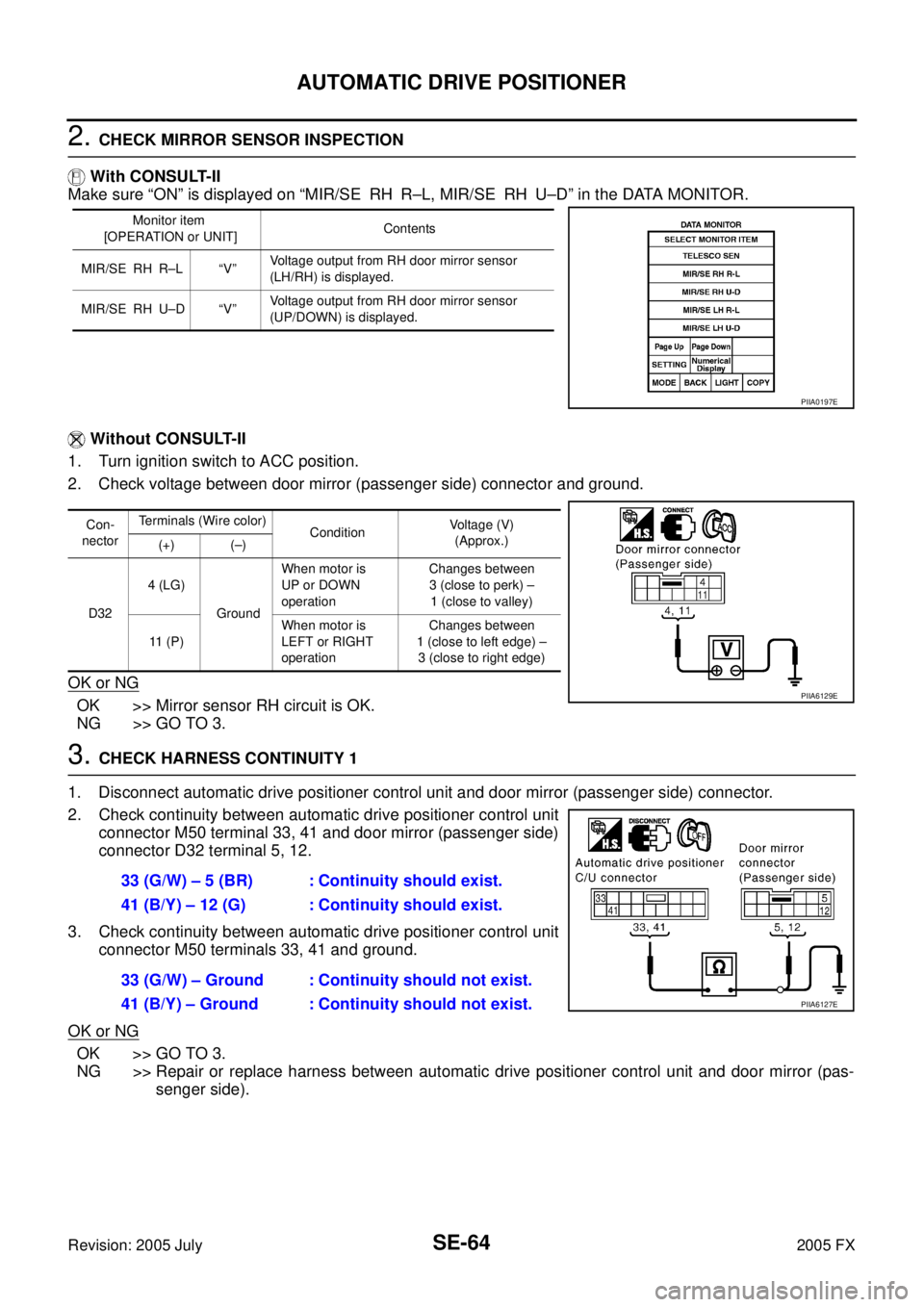
2. CHECK MIRROR SENSOR INSPECTION
With CONSULT-II
Make sure “ON” is displayed on “MIR/SE RH R–L, MIR/SE RH U–D” in the DATA MONITOR.
Without CONSULT-II
1. Turn ignition switch to ACC position.
2. Check voltage between door mirror (passenger side) connector and ground.
OK or NG
OK >> Mirror sensor RH circuit is OK.
NG >> GO TO 3.
3. CHECK HARNESS CONTINUITY 1
1. Disconnect automatic drive positioner control unit and door mirror (passenger side) connector.
2. Check continuity between automatic drive positioner control unit connector M50 terminal 33, 41 and door mirror (passenger side)
connector D32 terminal 5, 12.
3. Check continuity between automatic drive positioner control unit connector M50 terminals 33, 41 and ground.
OK or NG
OK >> GO TO 3.
NG >> Repair or replace harness between automatic drive positioner control unit and door mirror (pas- senger side).
Monitor item
[OPERATION or UNIT] Contents
MIR/SE RH R–L “V” Voltage output from RH door mirror sensor
(LH/RH) is displayed.
MIR/SE RH U–D “V” Voltage output from RH door mirror sensor
(UP/DOWN) is displayed.
PIIA0197E
Con-
nector Terminals (Wire color)
Condition Voltage (V)
(Approx.)
(+) (–)
D32 4 (LG)
Ground When motor is
UP or DOWN
operation Changes between
3 (close to perk) –
1 (close to valley)
11 ( P ) When motor is
LEFT or RIGHT
operation Changes between
1 (close to left edge) – 3 (close to right edge)
PIIA6129E
33 (G/W) – 5 (BR) : Continuity should exist.
41 (B/Y) – 12 (G) : Continuity should exist.
33 (G/W) – Ground : Continuity should not exist.
41 (B/Y) – Ground : Continuity should not exist.
PIIA6127E
Page 4538 of 4731

AUTOMATIC DRIVE POSITIONER SE-65
C
D E
F
G H
J
K L
M A
B
SE
Revision: 2005 July 2005 FX
4. CHECK HARNESS CONTINUITY 2
1. Check continuity between automatic drive positioner control unit connector M49 terminal 5, 21 and door mirror (passenger side)
connector D32 terminal 4, 11.
2. Check continuity between automatic drive positioner control unit connector M49 terminal 5, 21 and ground.
OK or NG
OK >> Check the condition of the harness and connector.
NG >> Repair or replace harness between automatic drive positioner control unit and door mirror (pas-
senger side).
Steering and Door Mirror Sensor Power and Ground Circuit CheckAIS003GA
1. CHECK MIRROR SENSOR POWER SUPPLY
1. Turn ignition switch OFF.
2. Check voltage between automatic drive positioner control unit connector M50 terminal 33 and ground.
OK or NG
OK >> GO TO 2.
NG >> Replace automatic drive positioner control unit.
2. CHECK MIRROR SENSOR GROUND CIRCUIT
Check continuity between automatic drive positioner control unit
connector M50 terminal 41 and ground.
OK or NG
OK >> GO TO 3.
NG >> Replace automatic drive positioner control unit. 5 (OR) – 4 (LG) : Continuity should exist.
21 (G/Y) – 11 (P) : Continuity should exist.
5 (OR) – Ground : Continuity should not exist.
21 (G/Y) – Ground : Continuity should not exist.
PIIA6128E
33 (G/W) – Ground : Approx. 5V
PIIA4778E
41 (B/Y) – Ground : Continuity should exist.
PIIA4779E